Table of Contents
Advertisement
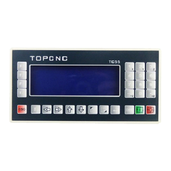
TC5510/TC5522/TC5530/TC5522R/TC5530R
TC5510/TC5522/TC5530/TC5522R/TC5530R
TC5510/TC5522/TC5530/TC5522R/TC5530R
TC5510/TC5522/TC5530/TC5522R/TC5530R
Motion
Motion
Controller
Controller
Motion
Motion Controller
Controller (Stepping
Left View
(Stepping
(Stepping
Motor
Motor
(Stepping Motor
Motor Controller)
Full figure
Back view
TC55 Breakout Board (TC55-MOD)
Controller)
Controller)
Manual
Manual
Controller) Manual
Manual
Right View
Advertisement
Table of Contents

Related Manuals for Topcnc TC5510


Summary of Contents for Topcnc TC5510
- Page 1 TC5510/TC5522/TC5530/TC5522R/TC5530R TC5510/TC5522/TC5530/TC5522R/TC5530R TC5510/TC5522/TC5530/TC5522R/TC5530R TC5510/TC5522/TC5530/TC5522R/TC5530R Motion Motion Controller Controller (Stepping (Stepping Motor Motor Controller) Controller) Manual Manual Motion Motion Controller Controller (Stepping (Stepping Motor Motor Controller) Controller) Manual Manual Full figure Left View Back view Right View TC55 Breakout Board (TC55-MOD)
-
Page 2: Table Of Contents
Note: TC55 series exactly same panel size shell film. Note: Note: Note: The The TC55 TC55 TC55 series series series are are exactly exactly exactly the the same same same panel panel panel size size size and and shell shell shell film. - Page 3 1. 1. 1. 1. Outline Outline Outline Outline The TC55 panel-type motion controller (CNC system) uses high-performance 32-bit CPU. The drive device adopts subdivision stepping motor or AC servo motor. It is equipped with LCD monitor and fully enclosed touch-type operating keyboard. The system has high reliability, high precision, low noise, easy to operate etc.
- Page 4 Applicable product type: CNC drilling machine system, CNC lathe system, CNC milling machine system, CNC grinding machine system l cutting machine control system, welding control system, dispenser control system, feeding control system displacement platform, one-dimensional control platform, two-dimensional control platform, three-dimensional control platform l threading machine control system, screwdriving machine control system l spraying production line control system, assembly production line control system, the meter counter control system...
-
Page 5: Connection
High-performance, high-speed 32-bit CPU High-grade black and white double color LCD monitor (resolution: 192 × 64) Special motion control chip (signal output: 5V TTL) Universal customizable input / output (16 photoelectric isolated 24V inputs, 8 relay outputs) User processing program memory (can store 20 programs) Minimum data unit 0.001 mm Maximum data size ±... - Page 6 8P. Similarly Similarly TC5522 TC5522 TC5522 or or or or TC5510 TC5510 only only take take the the first 8P. Similarly Similarly TC5522 TC5522R TC5522R only only...
- Page 7 2.2.1 Input wiring diagram 2.2.1 2.2.1 2.2.1 Input Input Input wiring wiring wiring diagram diagram diagram one of of of of input input input port port 1-16 1-16 Any one input port port 1-16 1-16 The negative negative negative negative electrode electrode electrode electrode of of of of 24V...
-
Page 8: Operation
Boot and enter into the main operation interface after showing the boot screen AutoExec Automatically execute Man OP Manual operation ProgMgmt Program management File Pars Set Parameter settings The picture shows the main interface of TC5510 after boot. The picture shows the main interface of TC5522 or TC5522R after boot. - Page 9 The picture shows the main interface of TC5530 or TC5530R after boot. 1. 1. 1. 1. The screen screen area area The screen screen area area AutoExec : Automatically execute. Click to enter the program execution interface, including the default Actl Run(Actual running), Mt Run (Empty running), SS Mo(Single-step mode running), TrmtProg(Terminate program).
- Page 10 Pars Set: Parameters settings. Click to enter the parameter setting interface, including Sys Pars(System parameters), Sys SC(System self-check), IO Set(IO settings), Usr Mgmt(User management). X X X X : The current coordinate position Y Y Y Y : The current coordinate position Z Z Z Z :...
- Page 11 0-9: Valid in the Ed Prog(Edit program) state or Pars Set(Parameters settings) state. (0、1、2、3、4、5、6、7、8、9) 1-3:In the Man Op(Manual operation) state, long press 1 key for three seconds, you can modify the X-axis coordinate to "X-axis mechanical reference point value", which is set in the Sys Pars(System parameters) area of Pars Set (Parameters settings) area.
- Page 12 the ProgMgmt(Program management) state or Pars Set(Parameters settings) state and used to move the cursor. “→” “→” “→”: In the Man Op(Manual operation) state, X-axis is forward rotation. It is valid in “→” the ProgMgmt(Program management) state or Pars Set(Parameters settings) state and used to move the cursor.
-
Page 13: Autoexec(Automatically Execute)
parameters or entering password for user login, press the Cfm(Confirm) key to determine to modify parameters or user login successfully. Spc: Space. It is valid in the Ed Prog(Edit program) state or Pars Set(Parameters settings) state and used to clear(delete) the value of the current cursor position. St: Start. -
Page 14: Mt Run(Empty Running)
settings) area, the controller begins running with the default last read-in program file. Press the Paus(Pause) key to pause the running program. To continue to execute the paused program file, press the St(Start) key again. To exit the program and remain in the AutoExec(Automatically execute) interface, press the TrmtProg(Terminate program) key. -
Page 15: Trmtprog(Terminate Program)
3.1.3 3.1.3 Single-step Single-step execution execution 3.1.3 3.1.3 Single-step Single-step execution execution In the Actl Run(Actual running) or Mt Run(Empty running) state, if SS Mo(Single-step mode) is not chosen, the system default is in the program continuous running mode and the SS Mo(Single-step mode) key color is not negative display. If press the left F3 key corresponding to SS Mo(Single-step mode), the SS Mo(Single-step mode) key color is negative display and in the Actl Run(Actual running) or Mt Run(Empty running) state, program runs with Single-step mode. -
Page 16: Man Op(Manual Operation)
Man HSpd(Manual high speed) Jog Op(Jog operation) BkTProg0(Back to program zero) BkTMech0(Back to mechanical zero) At this time, the default is Man LSpd(Manual low speed). The speed parameter is set in the Spd Pars(Speed parameters) area of the Pars Set(Parameters settings) area, and is the fixed mode(the rate key is valid ). -
Page 17: Jog Op(Jog Operation)
3.2.2 3.2.2 Op(Jog Op(Jog operation) operation) 3.2.2 3.2.2 Jog Jog Op(Jog Op(Jog operation) operation) In the Man Op(Manual operation) interface, press the left F2 key to enter the Jog Op(Jog operation) interface. At this time, the Jog Op(Jog operation) key color is negative display, and the system is in the Jog operation state. -
Page 18: Bktmech0(Back To Mechanical Zero)
3.2.4 3.2.4 3.2.4 3.2.4 BkTMech0(Back BkTMech0(Back to to to to mechanical mechanical zero(mechanical reference point)) BkTMech0(Back BkTMech0(Back mechanical mechanical zero(mechanical zero(mechanical zero(mechanical reference reference reference point)) point)) point)) In the Man Op(Manual operation) interface, press the left F4 key to enter the BkTMech0(Back to mechanical zero) interface. - Page 19 program instructions) with Bk0 HSpd(Back to zero high speed), until touch the zero point switch of the axis and the switch status changes from Open to Closed. 2).After touching the zero point switch, move with the speed quickly reduced to Bk0 LSpd(Back to zero low speed), until pass the switch and the switch status changes from Closed to Open.
- Page 20 Note: The machine tool limit switch is used as an example in the above figures. Also the photoelectric switch can be used as the zero point switch, similarly. Back to zero mode II: 1). Firstly move to the pressed key direction(or the direction specified by the program instructions) with Bk0 HSpd(Back to zero high speed), until touch the zero point switch of the axis and the switch status changes from Open to Closed.
-
Page 21: Progmgmt(Program Management)
switch changes from Closed to Open. At this time, stop instantly, the action of Back to mechanical zero is completed and the axis coordinate on the controller interface changes to the axis reference point value. The axis reference point value is set in the CtrlPars (Control parameters) area of the Pars Set(Parameters settings) area. - Page 22 In the ProgMgmt(Program Management) interface, press the left F1 key to enter the Ed Prog(Edit program) interface. In this interface, we can modify or rebuild the read-in file or the last open file before the shutdown. PgUpInst Page up instruction PgDnInst Page down instruction Ins 1Row Insert a row Del 1Row Delete a row...
- Page 23 Example: In the interface, n001 Lin M File:1144 press PgDnInst once, then becomes n001 PTP M File: 1144 That is, in the n001 line,modify the old Lin M(Linear motion) instruction to the PTP M ( Point to Point motion ) instruction, and new instruction parameter shows simultaneously.
- Page 24 Example: In the interface, n001 Lin M File:1144 n002 Outp File:1144 press Del 1Row once, then the line becomes n001 Outp File: 1144 (The instruction in the old n001 line is deleted.) Modify program: Modify Modify Modify program: program: program: In the Ed Prog(Edit program)state, according to the open file, find the line number need to be modified through the PgUp or PgDn key on the controller panel, and find the required instruction through the F1 or F2 on the controller panel left side...
-
Page 25: Prog Ri(Program Read-In)
the file name is undefined. 3.3.2 3.3.2 Prog Prog RI(Program RI(Program read-in) read-in) 3.3.2 3.3.2 Prog Prog RI(Program RI(Program read-in) read-in) In the ProgMgmt(Program Management) interface, press the left F2 key to enter the Prog RI(Program read-in) interface. In this interface, we can read-in the saved file. -
Page 26: Sv Prog(Save Program)
PrsCfmToDel Press the Confirm key to delete the file Move the cursor to choose the saved file through‘←’‘→’‘↑’‘↓’, and press the Cfm(Confirm) key to delete the chosen file according to the prompt. PrsCfmToDel-OK Press the Confirm key to delete the file – Success 3.3.4 Sv Sv Prog(Save... -
Page 27: Pars Set(Parameters Settings)
SvAs Prog OK Save as the program successfully Save Prog OK Save the program successfully Pars Pars Set(Parameters Set(Parameters settings) settings) 3.4 Pars Pars Set(Parameters Set(Parameters settings) settings) In the main interface, press the left F4 key to enter the Pars Set(Parameters settings) interface. -
Page 28: Sys Pars(System Parameters)
axis reference points, Electronic gear, Increase speed time, Jog increment, the axis gaps, a lot of speed parameters of the axises. 3.4.1.1 3.4.1.1 CtrlPars(Control CtrlPars(Control parameters) parameters) 3.4.1.1 3.4.1.1 CtrlPars(Control CtrlPars(Control parameters) parameters) When enter the Sys Pars(System parameters) interface, the default is CtrlPars(Control parameters). - Page 29 the modified data. ToSavePars Press save to save the parameters PlsPrsCfm Press the Confirm key to save the parameters Save Pars OK Save the parameters successfully 3.4.1.2 Pars(Speed parameters) 3.4.1.2 3.4.1.2 3.4.1.2 Spd Spd Pars(Speed Pars(Speed Pars(Speed parameters) parameters) parameters) In the Sys Pars(System parameters) interface, press the left F2 key to enter the Spd Pars(Speed parameters) interface.
- Page 30 pressing the left F4 key corresponding to SavePars(Save parameters) and then pressing the Cfm(Confirm) key on the controller panel according to the prompt, save the modified data. 3.4.1.3 FacVal(Factory values) 3.4.1.3 3.4.1.3 3.4.1.3 FacVal(Factory FacVal(Factory FacVal(Factory values) values) values) In the Sys Pars(System parameters) interface, press the left F3 key to enter the FacVal(Factory values) interface.
- Page 31 detect whether or not the set input ports functions are normal and accurate corresponding. ActlOutp: ActlOutp: ActlOutp: Actual output. Through the controller manual operation to test the output ActlOutp: ports relays on/off, detect whether or not the output ports are normal and one-to-one.
-
Page 32: Sys Sc(System Self-Check)
Actl Inp Actual input Set Inp Setting input ActlOutp Actual output ProgOutp Program output O off Tst Actl Inp Test actual input Note: Note: when when there there there is is is is no no no no change, change, change, may be be be be as as as as follows follows follows... - Page 33 ExtStart(External start) is set N.O.( Normally open) and input port is set 3. Through switching on the external input port 3, the St(Start) status should change from O(Off) to I(On) on the second page of the controller interface. Note: when there there is is is is no no no no change,...
- Page 34 Note: Note: Note: Note: when when when when there there there there is is is is no no no no change, change, change, change, may may be be be be as as as as follows follows follows follows 24V power supply is not working properly The output signal line connection is not normal The corresponding relay is not working properly 3.4.2.4...
- Page 35 The program output point setting is wrong The output signal is not normal 3.4.3 Set(IO settings) 3.4.3 3.4.3 3.4.3 IO IO Set(IO Set(IO Set(IO settings) settings) settings) In the Pars Set(Parameters settings) interface, press the left F3 key to enter the IO Set(IO settings) interface.
- Page 36 Val valid N.O.Normally open N.C. Normally closed “Pt” Port InpPt input port Alm Inp Alarm Input EmStpInp Emergency stop input XAxs0X axis zero ExtStart External start ExtPause External Pause IcSp Inp Increase speed input RdSp Inp Reduce speed input Man XPos Manual X positive direction Man XNeg Manual X negative direction Through setting the parameters, determine the specific definition of the external input ports.
-
Page 37: Io Set(Io Settings)
Example: The external Man XPos(Manual X positive direction rotation) is set Vld(Valid). The input line No.6 is selected to connect the switch of Man XPos(Manual X positive direction rotation). The switch is N.O.(Normally open) switch. Before modification After modification 3.4.3.2 3.4.3.2 3.4.3.2 3.4.3.2 OutpPars(Output... -
Page 38: Usr Mgmt(User Management)
defined is when the external output line changes, the program can not be modified, just the parameter is modified simply. Note: The FacVal(Factory value), Save functions and application methods are the same as the above (Sys Pars(System parameters)). 3.4.4 3.4.4 3.4.4 3.4.4 Usr Usr Mgmt(User... - Page 39 Usr Login OK User login successfully Pwd Err Pls Entr Agn Password mistake, please enter again If the login is successful and pressing directly the Exit key on the controller panel, then the Pars Set(Parameters settings) area can be edited. After the editing is completed, you can re-enter the Usr Mgmt(User management), and select the Usr Quit(User quit).
-
Page 40: Programming
you can not modify the Pars Set(Parameters settings) area. 4. 4. 4. 4. Programming Programming Programming Programming The controller detailed instructions and cases In a new file, the default instruction is End in the all n001-n480 lines. Through pressing the left side F1(PgUpInst) or F2(PgDnInst) key, find the instruction need to be applied. - Page 41 coordinates. Example: n003 PTP M File: 3399 Lbl: 0 X: 20.000 Y: -34.125 Z: 12.320 Meaning: After completing the n002 line execution, then execute this line n003. X/Y/Z will run with the most high speed set in the Sys Pars(System parameters). The speed is the resultant speed.
- Page 42 Lbl: 0 X: 10.000 Y: 0 F: 660 Z: -16.880 Meaning: After completing the n005 line execution, then execute this line n006. X/Y/Z will run with the F value 660 speed. The speed is the resultant speed. The motion action is the linear interpolation (start at the same time, stop at the same time). Subject to the previous position, the X axis will move 10.000 to the positive direction, the Y axis will not move, the Z axis will move 16.880 to the negative direction.
- Page 43 X/Y/Z will run with the F value 880 speed. The speed is the resultant speed. The motion action is the linear interpolation (start at the same time, stop at the same time). Subject to the last powered or set coordinates, the X axis will move to the coordinate 30.000 position, the Y axis will not move, the Z axis will move to the coordinate -16.880 position.
- Page 44 Programming is as follows: n001 Lin M File:7788 Lbl:0 X: 10.000 Y: 8.000 F:1000 Z: 0.000 n002 Lin M File:7788 Lbl:0 X: 0.000 Y: 0.000 F:100 Z: -6.000 n003 CirIntrp File:7788 Lbl:0 X: 15.000 Y: 8.660 R: 5 F:100 n004 Abs M File:7788 Lbl:0...
- Page 45 F:100 Z: 0.000 n005 Abs M File:7788 Lbl:0 X: 0.000 Y: 0.000 F:1000 Z: -------- Example 2: The controller is powered, quickly move to the X10, Y8 position of the point A, and then Z slowly moves down -6, and then clockwise draw the circular arc to the point B, the radius is 5, the circular arc is 2/3 of the full circle, and then Z moves up 6, then X,Y return back to program zero.
- Page 46 Y: 0.000 F:100 Z: -6.000 n003 CirIntrp File:7788 Lbl:0 X: 15.000 Y: 8.660 R: -5 F:100 n004 Abs M File:7788 Lbl:0 X: -------- Y: -------- F:100 Z: 0.000 n005 Abs M File:7788 Lbl:0 X: 0.000 Y: 0.000 F:1000 Z: -------- (The only difference of the two program segment is that the radius is positive or negative.) 5)IvCrItrp(Inverse circular interpolation): The X, Y axises, in the interpolation way,...
- Page 47 Example 1: The controller is powered, quickly move to the X10, Y8 position of the point A, and then Z slowly moves down -6, and then counterclockwise draw the circular arc to the point B, the radius is 5, the circular arc is 1/3 of the full circle, and then Z moves up 6, then X,Y return back to program zero.
- Page 48 X: 15.000 Y: 8.660 R: 5 F:100 n004 Abs M File:7788 Lbl:0 X: -------- Y: -------- F:100 Z: 0.000 n005 Abs M File:7788 Lbl:0 X: 0.000 Y: 0.000 F:1000 Z: -------- Example 2: The controller is powered, quickly move to the X10, Y8 position of the point A, and then Z slowly moves down -6, and then counterclockwise draw the circular arc to the point B, the radius is 5, the circular arc is 2/3 of the full circle, and then Z moves up 6, then X,Y return back to program zero.
- Page 49 Lbl:0 X: 10.000 Y: 8.000 F:1000 Z: 0.000 n002 Lin M File:7788 Lbl:0 X: 0.000 Y: 0.000 F:100 Z: -6.000 n003 IvCrItrp File:7788 Lbl:0 X: 15.000 Y: 8.660 R: -5 F:100 n004 Abs M File:7788 Lbl:0 X: -------- Y: -------- F:100 Z:...
- Page 50 instructions. 6)SetCoord(Set coordinates): Set the current position coordinates. When executing this line instruction, the controller will be subject to the current set new coordinates, the interface coordinates display will also be subject to the new coordinates. Example: The power is turned on, with the 660 mm/min speed, the program moves the absolute coordinate three positions to 20.000 mm, and then set the current point to the program running coordinate 0,0,0 point, and then all run 25 mm, then set the current point to the program running coordinate 0,0,0 point.
- Page 51 Y: 25.000 F:660 Z: 25.000 (At this time, the controller interface coordinates display is X: 25.000 Y: 25.000 Z: 25.000) n004 SetCoord File:7788 Lbl:0 X: 0.000 Y: 0.000 Z: 0.000 (At this time, the controller interface coordinates display is X: 0.000 Y: 0.000 Z: 0.000)...
- Page 52 Lbl:0 X: 10.000 Y:-15.000 F:1000 Z: 0.000 n002 Delay File:7788 Lbl:0 Dla Time: 5.25 n003 Abs M File:7788 Lbl:0 X: 0.000 Y: 0.000 F:1000 Z: 0.000 (Dla Time: Delay time) 8 ) Abs Jump(Absolute jump): When executing this line, jump to the place which Lbl(Label) is the same with the Dest Lbl(Destination label) to start to continue, equivalent to the infinite time (unlimited) loop instruction.
- Page 53 (Because at last start from this line to make the infinite loop, in the Lbl(Label) position of the starting line at the beginning of the loop, take a numerical marking name, and in the program file, the Lbl(Label) of each line instruction can not repeat, except 0, that is not defined.)...
- Page 54 must be applied at the same time. Detect the selected input port state(I(On) or O(Off)), if the set condition state of the instruction meets with the state of the external set input port, jump to the place which Lbl(Label) is the same as the current line Dest Lbl(Destination label), to start to continue, if does not meet with the external input port state, automatically execute the next line.
- Page 55 in the off state, then continues to loop the line instruction labeled 39.) (InpPt: Input port, Cond: Condition, O: Off, Dest Lbl:Destination label) n003 Lin M File:7788 Lbl:0 X: 0.000 Y: 20.000 F:800 Z: -15.000 Example 2: The program runs, waiting for the signal of the external input port 8, the input port closes once, while the three axises move 10mm at the same time, executes a total of 10 times.
- Page 56 Lbl:0 X: 10.000 Y: 10.000 F:800 Z: 10.000 n003 Loop File:7788 Lbl:0 NumOfLps:9 Dest Lbl:777 ( Execute this line, the program will automatically jump to the Lbl: 777 line instruction to continue to execute, the execution number of times is 9 times, accumulative total of 10 times, so when to execute a loop N times, the number of times of the loop instruction should be written as N-1 times.)...
- Page 57 delaying 3 seconds, turn off the output port, the three axises move 20 again from the current point, open the output port 1 and 2, delay 1 second, turn off the output port 1, and then delay 2 seconds, turn off the output port 2, and then the three axises position return back to coordinate zero.
- Page 58 Lbl:0 OutpPt:1 Stat:I n007 Output File:7788 Lbl:0 OutpPt:2 Stat:I n008 Delay File:7788 Lbl:0 Dla Time: 1 n009 Output File:7788 Lbl:0 OutpPt:1 Stat:O n010 Delay File:7788 Lbl:0 Dla Time: 2 n011 Output File:7788 Lbl:0 OutpPt:2 Stat:O n012 Abs M File:7788 Lbl:0 X:...
- Page 59 12)BkTMech0(Back to mechanical zero): Execute this instruction, through the set parameters of the instruction, execute the action of Back to the mechanical reference point, after completing the execution, the axis coordinate will clear the axis reference point value on the controller panel.(The reference point is set to 0 by default, and can be set any value according to demand.) Example: The mechanical reference point Y, Z is located in the program processing origin of coordinates -20 position, X-axis is rotation axis, do not set the mechanical...
- Page 60 Y: 0.000 F:800 Z: 0.000 n004 Lin M File:7788 Lbl:555 X: 20.000 Y: 0.000 F:800 Z: 0.000 n005 Lim M File:7788 Lbl:0 X: 0.000 Y: 30.000 F:600 Z: 30.000 n006 Loop File:7788 Lbl:0 NumOfLps:49 Dest Lbl:555 (BkTMech0: Back to mechanical zero Slctd Ax :The selected axis BkTo0Dir:Back to zero direction Ne:Negative)
- Page 61 14)Subr Bgn(Subroutine begin): Contains the subroutine name, and corresponding with Subr End(Subroutine end), both are indispensable. 15) Subr End(Subroutine end): Corresponding with Subr Bgn(Subroutine begin), both are indispensable. Example 1: Drilling hole, the Z axis is the drill axis. A row of holes, the pitch is 20 mm, a total of 30 holes, the hole depth is 10 mm.(The plunging and lifting is set the subroutine.) n001...
- Page 62 Subr Nm:100 n006 Lin M File:7788 Lbl:123 X: 0.000 Y: 0.000 F:100 Z: -10.000 n007 Abs M File:7788 Lbl : 123 X : --------- ( Change the value to ‘--------’ through the Cfm(Confirm) key, indicate that the axis does not move.) Y:...
- Page 63 n003 Loop File:7788 Lbl:0 NumOfLps:29 Dest Lbl:123 n004 File:7788 Lbl:0 n005 Subr Bgn File:7788 Lbl:0 Subr Nm:100 n006 Output File:7788 Lbl:0 OutpPt:1 Stat:I n007 CondJump File:7788 Lbl:89 InpPt: 1 Cond:O Dest Lbl:89 (The Input port 1 is the INPOS(In Position) signal. If touching the switch, the program will run downwards, or continue to wait.)...
- Page 64 Lbl:0 OutpPt:2 Stat:I n010 CondJump File:7788 Lbl:98 InpPt: 1 Cond:O Dest Lbl:98 n011 Output File:7788 Lbl:0 OutpPt:2 Stat:O n012 Subr End File:7788 Lbl:0 5. 5. 5. 5. Appendix Appendix Appendix Appendix 1. 1. 1. 1. Electronic Electronic gear calculation formula Electronic Electronic gear gear...
- Page 65 eliminate the calculation error), so that the impact of the decimal omitted by the numerator or denominator is minimal. Example 1: Screw Drive: The stepping motor drive is 5000 steps per revolution, or servo drive is 5000 pulses per revolution, the screw lead is 6 mm, the reduction ratio is 1:1, ie 1.0.
- Page 66 reduction ratio is 1:1, ie 1.0. Namely: the numerator is 1,the denominator is 60. � � � � Increasing Increasing Increasing reducing reducing speed speed curve curve settings settings Increasing and and reducing reducing speed speed curve curve settings settings The increasing and reducing speed curve is relative to the start speed, the X(Y,Z) axis high speed, and the increase speed time.
- Page 67 stall and not lost steps. Through changing the start speed, the X(Y,Z) axis high speed, and the increase speed time, the motion process can achieve the ideal state. When using a servo motor, the increasing and reducing speed curve should be efficient and no overshoot.
- Page 68 6. 6. 6. 6. Acronyms Acronyms Acronyms Abbreviations Abbreviations Acronyms and and Abbreviations Abbreviations A A A A Abs Jump Jump Jump Jump Absolute Absolute Absolute Absolute jump jump jump jump Abs M M M M Absolute Absolute motion motion Absolute Absolute motion motion...
- Page 69 F F F F FacVal FacVal FacVal FacVal Factory Factory Factory Factory default default default default value value value value FailedToSavePwd FailedToSavePwd FailedToSavePwd FailedToSavePwd Failed Failed Failed Failed to to to to save save save save user user user user’ ’ ’ ’ s s s s password password password password...
- Page 70 LSpd LSpd Manual Manual speed speed Man LSpd LSpd Manual Manual low low speed speed Man OP Manual Manual Manual Manual operation operation operation operation XNeg XNeg Manual Manual Manual X X X X negative negative negative direction direction Man XNeg XNeg Manual negative direction...
- Page 71 PrsCfmToSaveFile PrsCfmToSaveFile Press Press Confirm Confirm key to to to to save save save file file PrsCfmToSaveFile PrsCfmToSaveFile Press Press the the Confirm Confirm key save the the file file 按确认键保存密码 PrsCfmToSavePwd PrsCfmToSavePwd PrsCfmToSavePwd PrsCfmToSavePwd Pt Pt Pt Pt port port port port...
- Page 72 T T T T Test Test Test Test operation operation successfully successfully Test Test Op Op OK Test Test operation operation successfully successfully Test Test Test Test user user user user login login login login Test Test Test Test user user user user log...
Need help?
Do you have a question about the TC5510 and is the answer not in the manual?
Questions and answers