
Related Manuals for Reson SeaBat 8160

Summary of Contents for Reson SeaBat 8160
- Page 1 SeaBat 8160 Multibeam Echo Sounder System OPERATOR’S MANUAL SeaBat 8160 Operator‟s Manual Drawing Number 11282 October 6, 2011 Version 5 Part Number 86010021...
- Page 2 This page intentionally left blank. SeaBat 8160 Operator‟s Manual Drawing Number 11282 October 6, 2011 Version 5 Part Number 86010021...
- Page 3 Notice The information contained in this document is subject to change without notice. RESON makes no warranty of any kind with regard to this material, including (but not limited to) the implied warranties of merchant liability and fitness for a particular purpose.
- Page 4 This page intentionally left blank. SeaBat 8160 Operator‟s Manual Drawing Number 11282 October 6, 2011 Version 5 Part Number 86010021...
-
Page 5: Table Of Contents
Operator Safety ..................12 Equipment Safety ................. 12 3.3.1 Safe Handling................13 3.3.2 Cleaning and Maintenance of Projector and Receiver Arrays ..13 Electrical Isolation ................15 SeaBat 8160 Operator‟s Manual Drawing Number 11282 October 6, 2011 Version 5 Part Number 86010021... - Page 6 5.4.4 Change the Pulse Width (TxPulse) ..........28 5.4.5 Change the Receiver Gain (RxGain) ..........28 5.4.6 Change the Gain Mode (Gain Mode) ..........28 SeaBat 8160 Operator‟s Manual Drawing Number 11282 October 6, 2011 Version 5 Part Number 86010021...
- Page 7 Calibrate the System (Calib Button) ..........43 5.10 Changing Display Mode ............... 44 APPENDIX A DEPTH GATES AND HEAD TILT ......45 Introduction ..................45 Depth Gates ..................45 SeaBat 8160 Operator‟s Manual Drawing Number 11282 October 6, 2011 Version 5 Part Number 86010021...
- Page 8 Servicing During Warranty Period ............114 Equipment Return Procedure ............. 114 Service ....................114 APPENDIX H WEIGHTS AND MEASURES ......... 115 Metric Conversion ................115 SeaBat 8160 Operator‟s Manual Drawing Number 11282 October 6, 2011 Version 5 Part Number 86010021...
- Page 9 Figure 28: Sign Convention for Sonar Processor ..........77 Figure 29: Sonar Latency Drawing ..............82 Figure 30: Uplink Example ................. 89 Figure 31: SeaBat 8160 System, Sheet 1 ............93 Figure 32: SeaBat 8160 System, Sheet 2 ............94 Figure 33: Array, Installation Template ............... 95 Figure 34: Array, Outline and Installation Drawing ..........
- Page 10 Table 27: Uplink Encoding Scheme From 4-Bit Nibbles to 5-Bit Codes ..... 90 Table 28: Downlink Technical Specifications ............91 Table 29: MBES Sidescan Specifications ............111 Table 30: Metric Conversion Table ..............115 SeaBat 8160 Operator‟s Manual Drawing Number 11282 October 6, 2011 Version 5...
-
Page 11: Introduction
INTRODUCTION 1 INTRODUCTION 1.1 System Overview The SeaBat 8160 is a 50kHz Mulitbeam Echo Sounder (MBES) system that measures relative water depths across a wide swath perpendicular to a vessel‟s track. 1.2 How to Use this Manual This manual is designed to accommodate both the first time user, who needs detailed instructions, and the experienced technician, who only requires a reference tool. -
Page 12: Notes And Warnings
All notes and warnings will be shown in the following format: NOTE This is a Note. Notes provide explanatory information that may be useful to the operator, but is not necessarily vital to the operation of your RESON system. CAUTION This is a Caution. Cautions provide important information regarding your RESON system. - Page 13 Glossary of Terms: Definitions of acronyms and technical terms used in this manual. If you require additional information or need clarification of any part of this document, please contact RESON Customer Support for assistance at support@reson.com. SeaBat 8160 Operator‟s Manual...
-
Page 14: System Components
SYSTEM COMPONENTS 2 SYSTEM COMPONENTS 2.1 Chapter Overview This chapter outlines basic information and technical specifications for the components of your SeaBat 8160 system. 2.2 Sonar Processor The sonar processor is a dedicated computer that is responsible for the following functions: ... -
Page 15: Illustrations
Operating: 0 to +40 C Storage: -30 to +55 C * S-Video and Auxiliary outputs can be either NTSC or PAL format. 2.2.2 Illustrations Figure 1: Sonar Processor Dimensions SeaBat 8160 Operator‟s Manual Page 5 October 6, 2011 Version 5... -
Page 16: Transceiver Unit
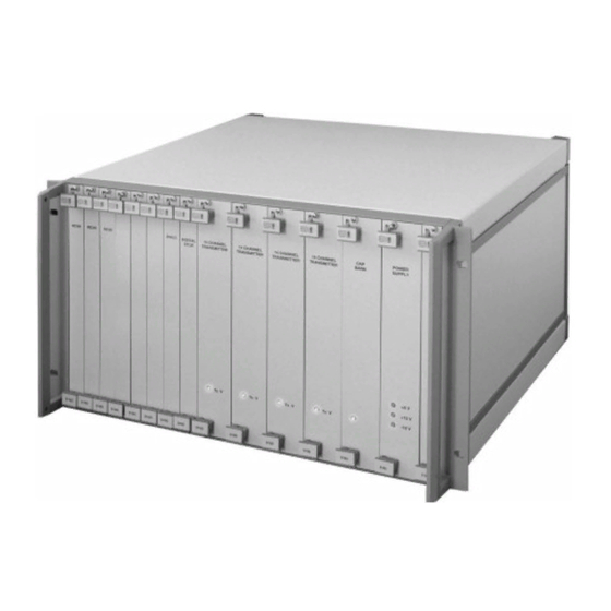
The technical specifications of the transceiver unit are listed in Table 3. Table 3: Transceiver Unit, Technical Specifications Specification Value Power Requirements 24VDC (from sonar processor) Mounting 19-inch rack SeaBat 8160 Operator‟s Manual Page 6 October 6, 2011 Version 5... -
Page 17: Illustrations
Length: 497mm Height: 267mm (See Figure 3 for details) Weight 13.6kg Temperature Operating: 0º to +40º C Storage: -30º to +55º C 2.3.2 Illustrations Figure 3: Transceiver Unit, Dimensions SeaBat 8160 Operator‟s Manual Page 7 October 6, 2011 Version 5... -
Page 18: Processor To Transceiver Interconnection Cable
The standard cable length is 20 meters. Longer cables (up to 150 meters) may be ordered from RESON and will require adjustments to the hardware. -
Page 19: Table 4: Sonar Array Technical Specifications
Specification Value Across-Track Beam Width 1.5 (at nadir beam*) Along-Track Beam Width 1.5, 3.0, 4.5, or 6.0 (based on operator selection) Beam Spacing 1.2 15 Beam Pitch Stabilization SeaBat 8160 Operator‟s Manual Page 9 October 6, 2011 Version 5... -
Page 20: Illustrations
The color monitor supplied with the SeaBat™ system is a standard PC- compatible monitor. Please refer to the manufacturer‟s user‟s guide for technical information. Other monitors, for applications requiring NTSC or PAL video, are available as a special option. SeaBat 8160 Operator‟s Manual Page 10 October 6, 2011 Version 5... -
Page 21: Trackball
2.6.2 Trackball The trackball supplied with the SeaBat™ system is a three-button unit that has been modified by RESON for use with the sonar processor. In the event of damage or failure, a replacement must be obtained from RESON. SeaBat 8160 Operator‟s Manual... -
Page 22: Safety Precautions
This chapter contains information as to the safety precautions that should be taken in handling and operating your SeaBat™ system. 3.2 Operator Safety The SeaBat 8160 system should be handled with attention to operator safety as well as protection of the hardware components. General precautions include: ... -
Page 23: Safe Handling
The acoustic window molded over the front of the projector and receiver arrays is made of high-density polyurethane. A long range of chemicals will destroy the polyurethane, which include, but are not limited to: SeaBat 8160 Operator‟s Manual Page 13 October 6, 2011... - Page 24 To scrape away marine growth from the arrays, use only a wooden tool. Do not apply any antifouling paint on the acoustic window unless the type is recommended by RESON. The antifouling paint will affect the acoustic performance. RESON recommends: o For high-frequency transducers (>100kHz) use International VC 17m.
-
Page 25: Electrical Isolation
(keyboard, mouse, etc.). By ensuring this product is disposed of correctly, you will help protect the environment. For more detailed information about the recycling of this product, please contact your local authority, your household waste disposal service provider, or RESON Customer Support (support@reson.com). SeaBat 8160 Operator‟s Manual... -
Page 26: Installation Instructions
4 INSTALLATION INSTRUCTIONS 4.1 Chapter Overview This chapter outlines basic information and technical specifications for the components of your SeaBat 8160 system. 4.2 Dry End Installation Following are instructions for use when installing the dry end components of the SeaBat 8160 system. -
Page 27: Cable Connections
When connecting the transceiver to processor cable, use a minimum bend radius of 125mm or a minimum bend diameter of 250mm. A smaller bend radius will result in damage to the cable. SeaBat 8160 Operator‟s Manual Page 17 October 6, 2011... -
Page 28: Wet End Installation
INSTALLATION INSTRUCTIONS 4.3 Wet End Installation Following are detailed instructions for use when installing the SeaBat 8160 system in a single-head configuration on a surface vessel. Detailed installation drawings are provided in Appendix D for reference. NOTE Prior to installation, wrap all dry-end connectors in a protective covering to prevent accumulation of dirt and moisture. -
Page 29: Orientation
It is very important that the index mark on the face of the hydrophone be oriented to starboard. Starboard Hydrophone Index Mark (Face View) Figure 10: Hydrophone Face with Starboard Index Mark SeaBat 8160 Operator‟s Manual Page 19 October 6, 2011 Version 5... -
Page 30: Acoustic Center
There are eleven possible connect points at the rear of the SeaBat™ transceiver unit (Figure 12). These connect points are numbered J1 – J14 (note that J10, J11, and J12 are not used by this system). SeaBat 8160 Operator‟s Manual Page 20 October 6, 2011... -
Page 31: Figure 12: Transceiver Unit, Rear Panel
Use a minimum bend radius of 250mm or a minimum bend diameter of 500mm when positioning the cables. These cables are very stiff, and a smaller bend radius will result in damage to the cable. SeaBat 8160 Operator‟s Manual Page 21 October 6, 2011... -
Page 32: System Checkout
4.4 System Checkout Once the components of your SeaBat 8160 system have been installed, follow the steps in this section to ensure that the system is working properly. 1. Ensure all system cable connections are tight. - Page 33 NOTE In a noisy environment, it may be difficult to hear the transmission, which should be a series of clicks at an approximate rate of 4Hz on the 100m range. SeaBat 8160 Operator‟s Manual Page 23 October 6, 2011 Version 5...
-
Page 34: System Operation
SYSTEM OPERATION 5 SYSTEM OPERATION 5.1 Chapter Overview The SeaBat 8160 system is controlled by firmware that has been pre-loaded on the sonar processor. Information with regards to the operation of the firmware is contained in this chapter. 5.2 Start Up Procedure Once the SeaBat™... -
Page 35: View The Sonar Image
Sonar Display (see Figure 13). This time is provided by a battery-powered clock/calendar within the sonar processor. To adjust the time setting, see sections C.3.1.12 Date and C.3.1.45 Time. SeaBat 8160 Operator‟s Manual Page 25 October 6, 2011 Version 5... -
Page 36: Menu Functions
SYSTEM OPERATION 5.3.4 Menu Functions The Menu Block (see Figure 13) is the primary control point for the SeaBat 8160 system. To modify items on this menu or on any sub-menus, place the mouse pointer over the item to be modified. A box will appear around the title and value. -
Page 37: Main Menu
7. Activate Automatic Gain. 5.4.1 Set the Range (Range) The “Range” setting determines how far the SeaBat 8160 will “see”. The range settings are operator selected between 5 and 5,000 meters. See Appendix B for available range options and their associated standard ping rates. -
Page 38: Change The Transmit Power (Txpower)
The Gain Mode selection provides the ability to dictate the type of gain that will be applied to the received signal. When switching between Gain Modes, the last gain value selected in each category will be restored upon selection. SeaBat 8160 Operator‟s Manual Page 28 October 6, 2011... -
Page 39: Activate Automatic Gain (Autogain)
A typical setting is “4,” however the optimal setting will vary with bottom type and other environmental conditions. NOTE The bottom detect process must have good quality return signals to allow AutoGain to work properly. SeaBat 8160 Operator‟s Manual Page 29 October 6, 2011 Version 5... -
Page 40: Ocean Menu
The range allowed is from 1350 to 1600m/sec. If the local sound velocity is not known, RESON recommends a value of 1480 to 1500m/sec for open sea areas and 1425m/sec for fresh water. See Figure 15 as a general reference for typical surface sound velocity at different temperatures and salinity. -
Page 41: Display Menu
This is a display setting only and has no effect on internal processing. 5.6.3 Color-Code Sounding Dots (Dots) The “Dots” menu item provides the option to color-code each sounding dot, depending on various factors. The choices available are: SeaBat 8160 Operator‟s Manual Page 31 October 6, 2011 Version 5... -
Page 42: Display Or Hide The Sonar Grid (Grid)
5.7 Filters Menu The Filters menu allows the operator to apply range and/or depth filters (depth gates) to the bottom-detect process to aid in noise reduction and to correct for a SeaBat 8160 Operator‟s Manual Page 32 October 6, 2011... -
Page 43: Apply A Filter (Filter)
The value entered here rotates the layer formed by the depth gates. Use this function to compensate for a sonar array with a roll offset in its mounting structure. The adjustment range is plus or minus 180 in 1 steps. SeaBat 8160 Operator‟s Manual Page 33 October 6, 2011... -
Page 44: Menu Off
The Menu Block may be re-activated by clicking on the line. 5.9 Built-In Test Environment (BITE) Display The Built-In Test Environment (BITE) display (see Figure 16) shows diagnostic and configuration information with regards to the current sonar session. SeaBat 8160 Operator‟s Manual Page 34 October 6, 2011 Version 5... -
Page 45: Figure 16: Built-In Test Environment (Bite) Display
4. Check the status of Sensor Inputs. 5. Review Offset graphs. 6. Configure the system to specific requirements. 7. Reset the system. 8. Calibrate the System. 9. Change the Display Mode. SeaBat 8160 Operator‟s Manual Page 35 October 6, 2011 Version 5... -
Page 46: Ping Indicator
If this indicator turns red, remove the sonar array from the water and contact a RESON Service Depot immediately. Head Temp: This feature is not currently enabled for the SeaBat 8160. CtrlTemp: Shown in degrees Celsius, this is the internal temperature of the transceiver unit. -
Page 47: Check The Firmware Version
SYSTEM OPERATION 5.9.3 Check the Firmware Version This item shows the version number of the firmware on both the sonar processor and the transceiver unit. These numbers are necessary when contacting RESON for support. NOTE To ensure compatibility of the units, the sonar processor checks the version of the transceiver unit at power-on. -
Page 48: Check The Status Of Sensor Inputs
(Slight channel-to-channel variations are normal.) Receiver Gain Offsets: Condition Color Value < 2.0dB Acceptable Green ≥ 2.0dB to < 3.5dB Marginal Yellow ≥ 3.5dB Extreme SeaBat 8160 Operator‟s Manual Page 38 October 6, 2011 Version 5... -
Page 49: Configure System To Specific Requirements
Click the “CALIB” button while holding down the center mouse button to present uncorrected values. 5.9.7 Configure System to Specific Requirements The Config Menu allows the operator to integrate the SeaBat 8160 to any vessel‟s specific requirements. 5.9.7.1 Select Uplink Port (Uplink) Select the uplink port to be used. - Page 50 Defines whether the sonar array is oriented with the transmit array forward or aft of the hydrophone. ProjFwd: The transmit array is forward of the hydrophone. ProjAft: The transmit array is aft of the hydrophone. SeaBat 8160 Operator‟s Manual Page 40 October 6, 2011 Version 5...
-
Page 51: Modes Menu
4% of that depth. 5.9.8.3 Activate Sidescan (Sidescan) Selects the Sidescan operating mode. See Appendix F for details. SeaBat 8160 Operator‟s Manual Page 41 October 6, 2011 Version 5... - Page 52 Pitch Stabilization options. OFF: Pitch stabilization is not used. STAB: Pitch is stabilized using the most recent value from the Motion Sensor. SeaBat 8160 Operator‟s Manual Page 42 October 6, 2011 Version 5...
-
Page 53: Reset The System (Reset Button)
Click this button to reboot the firmware in the sonar processor and initiate the calibration routine. 5.9.10 Calibrate the System (Calib Button) Initiate the process which calibrates the electronics associated with each of the ceramic elements that constitute the receiver array. SeaBat 8160 Operator‟s Manual Page 43 October 6, 2011 Version 5... -
Page 54: Changing Display Mode
Left and Right buttons to return to S-VGA format. NOTE The standard S-VGA monitor issued with the SeaBat 8160 system is not compatible with NTSC and PAL formats and will be blank when either is selected. If an NTSC or PAL format is required, a separate compatible monitor must be used with the system. -
Page 55: Appendix A Depth Gates And Head Tilt
(no motion sensor applied) depth gates. In this figure and all remaining figures, the bottom is flat. SeaBat 8160 Operator‟s Manual Page 45 October 6, 2011... -
Page 56: Offsetting The Sonar Array
SeaBat 8160 Operator‟s Manual Page 46 October 6, 2011... -
Page 57: Head Tilt Function
Tilt menu item, the layer formed by the depth gates will be rotated by the same thirty degrees, as shown in For this discussion, the operator must enter negative numbers for a starboard off- set and positive numbers for port. SeaBat 8160 Operator‟s Manual Page 47 October 6, 2011 Version 5... -
Page 58: Figure 23: Depth Gates With Offset
The use of depth gates and other filters is a very delicate and potentially error- prone process. Exercise extreme caution when applying depth and range filters, as incorrect settings will result in erroneous and/or lost data. SeaBat 8160 Operator‟s Manual Page 48 October 6, 2011... -
Page 59: Appendix B System Ping Rates
APPENDIX B SYSTEM PING RATES To aid in the calculation of sounding density, the following table provides ping rates for the SeaBat 8160 system. Sound Velocity = 1500 meters/sec, HeadSync = 1, MaxRate = 15 pings/sec. (Snippets mode reduces the ping rate on some range scales.) - Page 60 (ping) rate which, in turn, is controlled by the range selected. Ping Rate is determined by the Round Trip Time. This time is strongly affected by the local speed of sound in water. SeaBat 8160 Operator‟s Manual Page 50 October 6, 2011...
-
Page 61: Appendix C Interface Specifications
6. Ethernet Port (10 Base 2): - IN: Command Messages / Firmware download, OUT: Bathy Data / Sidescan. Use either 4 or 6, do not use both at the same time. SeaBat 8160 Operator‟s Manual Page 51 October 6, 2011... -
Page 62: Hardware Interface Settings
Port 1 is used for sending bathymetric and receiving time stamp data. Table 8: Serial Port 1 Specifications Description Setting Connector Label RS-232 Port 1 Baud Rate IN 1200, 2400, 4800, 9600, 19200, 38400, 57600 or 115200 SeaBat 8160 Operator‟s Manual Page 52 October 6, 2011 Version 5... -
Page 63: Table 9: Serial Port 2 Specifications
Table 10: Serial Port 3 Specifications Description Setting Connector Label RS-232 Port 3 Baud Rate IN 1200, 2400, 4800, 9600, 19200, 38400, 57600 or 115200 Baud Rate OUT Data Bits Parity None Stop Bits SeaBat 8160 Operator‟s Manual Page 53 October 6, 2011 Version 5... -
Page 64: Table 11: Downlink 1 Specifications
5 (ground) and pin 2 (data) connected. The sonar processor transmits the downlink on pin 3 and ground on pin 5. C.2.1.5 Ethernet Select either 10 Base-T (RJ45 connector) or 10 Base-2 (BNC connector) for network communication. SeaBat 8160 Operator‟s Manual Page 54 October 6, 2011 Version 5... -
Page 65: Figure 24: Straight-Through Cable Diagram
White/Green White/Orange Blue Blue White/Blue White/Blue Green Orange White/Brown White/Brown Brown Brown Figure 25: Cross-Over Cable Diagram Crossover Cable Straight-Through Cables Processor Processor Figure 26: Crossover vs. Straight-Through Configurations SeaBat 8160 Operator‟s Manual Page 55 October 6, 2011 Version 5... -
Page 66: Messages And Data Format
Start of Message (Asterisk) TYPE Message Type PARAMxxx Parameters for the Message <CR><LF> Carriage Return, Line Feed There are three different replies on a Command Message followed by <CR> and <LF> SeaBat 8160 Operator‟s Manual Page 56 October 6, 2011 Version 5... -
Page 67: Table 15: Command Message Reply Types
Parameters: N = 1: String Number 1 N = 2: String Number 2 STRING = Text to be displayed on the sonar screen. Example: *ANNO,1,RESON<CR><LF> This example will print the text “RESON” on the sonar screen display. SeaBat 8160 Operator‟s Manual Page 57 October 6, 2011... - Page 68 The parameter may be any number from 0 to the maximum range, as long as it is greater than or equal to the minimum range. Example: *BMAX,100,<CR><LF> This example sets the maximum range filter value to 100m. SeaBat 8160 Operator‟s Manual Page 58 October 6, 2011 Version 5...
- Page 69 Example: *BRIT,1,<CR><LF> This example sets the contrast to 1.00 times. C.3.1.8 Calibrate This message calibrates the system. Syntax: *CALB<CR><LF> Parameters: Example: *CALB<CR><LF> This example initiates the system calibration sequence. SeaBat 8160 Operator‟s Manual Page 59 October 6, 2011 Version 5...
- Page 70 Valid rates are: 1200, 2400, 4800, 9600, 19200, 38400, 57600, 115200 Example: *CTBR,115200<CR><LF> This example sets both the IN and OUT baud rates on serial prot 2 at 115200 baud. SeaBat 8160 Operator‟s Manual Page 60 October 6, 2011 Version 5...
- Page 71 N = 3: Quality (Displays all dots, color-coded with quality). N = 4: Process (Displays all dots, color coded depending on the bottom-detection algorithm.) Example: *DCHK,0<CR><LF> This example turns the dots off. SeaBat 8160 Operator‟s Manual Page 61 October 6, 2011 Version 5...
- Page 72 This message selects the output port for bathymetric data. Syntax: *DOUT,N<CR><LF> Parameters: N = 0: RS-232 N = 1: Ethernet Example: *DOUT,1<CR><LF> This example sets the sonar processor to send bathymetric data output to the Ethernet port. SeaBat 8160 Operator‟s Manual Page 62 October 6, 2011 Version 5...
- Page 73 This message tells the sonar processor the orientation for the head. Syntax: *FLIP,N<CR><LF> Parameters: N = 0: Projector forward/up. N = 1: Projector aft/down. Example: *FILP,0<CR><LF> This message tells sonar processor that the head is mounted with projector forward. SeaBat 8160 Operator‟s Manual Page 63 October 6, 2011 Version 5...
- Page 74 N = 1: Just the border. N = 2: Border and lines. N = 3: Full. Example: *GRID,1<CR><LF> This example sets the processor to display only the border around the wedge. SeaBat 8160 Operator‟s Manual Page 64 October 6, 2011 Version 5...
- Page 75 Parameters: N = Baud Rate. Valid Rates are 1200, 2400, 4800, 9600, 19200, 38400, 57600, 115200. Example: *BAUD,19200<CR><LF> This message sets the IN baud rate on serial port 3 to 19200. SeaBat 8160 Operator‟s Manual Page 65 October 6, 2011 Version 5...
- Page 76 This example sets the 81-P processor IP address to 10.0.1.245. C.3.1.27 Power This message sets the sonar transmitter power. Syntax: *POWR,N<CR><LF> Parameters: N = The power value. Example: *POWR,0<CR><LF> This message sets the power to OFF. SeaBat 8160 Operator‟s Manual Page 66 October 6, 2011 Version 5...
- Page 77 N = 5: Scan Test Example: *PROJ,0<CR><LF> For a SeaBat 8160, this example selects Steer 1.5. NOTE The projector selection varies for different SeaBat™ models. This setting will only apply to the SeaBat™ model for which this manual was written.
- Page 78 Sets transmit pulse-width to 0.0017 seconds. C.3.1.32 Range This message changes the range setting. Syntax: *RANG,N <CR><LF> Parameters: N = Range value in meters Example: *RANG,5<CR><LF> This example sets the range setting to 5m. SeaBat 8160 Operator‟s Manual Page 68 October 6, 2011 Version 5...
- Page 79 This message sets the raw output mode to 1 where 16 bit magnitude data (20 beams) are being exported. C.3.1.35 Reset This message resets the sonar processor. Syntax: *RSET<CR><LF> Parameters: Example: *RSET<CR><LF> This message resets the sonar processor. SeaBat 8160 Operator‟s Manual Page 69 October 6, 2011 Version 5...
- Page 80 C.3.1.38 Sound Speed This message sets the sound speed. Syntax: *SSPD,N<CR><LF> N – Sound speed value from 1350 to 1600m/s. Parameters: Example: *SSPD,1480<CR><LF> This example sets the sound speed to 1480m/s. SeaBat 8160 Operator‟s Manual Page 70 October 6, 2011 Version 5...
- Page 81 N = 4: Off. N = 5: Average old N = 6: RMS old N = 7: Full old Example: *STYP,1<CR><LF> This message sets the sidescan output to “Average New”. SeaBat 8160 Operator‟s Manual Page 71 October 6, 2011 Version 5...
- Page 82 This message selects the synchronization method between the sonar processors. Syntax: *SYNC,N<CR><LF> Parameters: N = 0: Stand-alone. N = 1: Slave. N = 2: Master. Example: *SYNC,0<CR><LF> The example sets the sonar processor to stand-alone. SeaBat 8160 Operator‟s Manual Page 72 October 6, 2011 Version 5...
- Page 83 Parameters: N = Baud rate. Valid rates are 1200, 2400, 4800, 9600, 19200, 38400, 57600, 115200. Example: *TMBR,19200<CR><LF> This message sets the In baud rate on Serial Port 1 to 19200. SeaBat 8160 Operator‟s Manual Page 73 October 6, 2011 Version 5...
- Page 84 This message selects the video mode. Syntax: *VMOD,N<CR><LF> Parameters: N = 0: NTSC N = 1: PAL. N = 2: SVGA. Example: *VMOD,1<CR><LF> This example sets the video mode to PAL. SeaBat 8160 Operator‟s Manual Page 74 October 6, 2011 Version 5...
-
Page 85: Table 16: Time Stamp Message Format
NOT be applied to the time. SeaBat 8160 Operator‟s Manual Page 75 October 6, 2011... -
Page 86: Table 17: Seabird Ct Message Format
Sound Velocity Meter per Second C.3.3.3 AML Smart Sensor Message: SVVVV.VVS<CR><LF> Table 19: AML Smart Sensor Message Format Field Description Unit VVVV.VV Sound Velocity Meter per Second Space Character SeaBat 8160 Operator‟s Manual Page 76 October 6, 2011 Version 5... -
Page 87: Figure 28: Sign Convention For Sonar Processor
Status Flag u, U, g, G, h, H, f, F MRRRR Roll -90° to 90° 0.01° MPPPP Pitch -90° to 90° 0.01° „ „ if positive or „-„ if negative SeaBat 8160 Operator‟s Manual Page 77 October 6, 2011 Version 5... -
Page 88: Table 21: Tss 335B Message Format
The binary format consists of a fixed-length message using single-byte unsigned and 4-byte IEEE floating point data elements. For the multi-byte elements, the most significant byte is transmitted first. Note: Each <> indicates one byte of data. SeaBat 8160 Operator‟s Manual Page 78 October 6, 2011 Version 5... -
Page 89: Table 23: Seatex Mru Message Format
Output NMEA 0183 compatible Data sent: Heading, roll, pitch, position, linear speed, compensation values and status Data frame: Syntax: $HEHDT,x.xx,T*hh<CR><LF> Parameters: x.xx = true heading in degrees = checksum Syntax: $PHTRO,x.xx,a,y.yy,b*hh<CR><LF> SeaBat 8160 Operator‟s Manual Page 79 October 6, 2011 Version 5... - Page 90 = latitude in degrees (two first l) and in minutes (four last l) a = N: Northern hemisphere a = S: Southern hemisphere xx.xx = speed in knots Syntax $PHINF,hhhhhhhh*hh<CR><LF> SeaBat 8160 Operator‟s Manual Page 80 October 6, 2011 Version 5...
-
Page 91: Table 24: Udp Port Offsets
TYPE OF DATA Bathymetric Data Sidescan (optional) Control / Status Alarm Snapshot Raw Beam Data (optional) Snippet Data (optional) The download port for new firmware is fixed at 8100. SeaBat 8160 Operator‟s Manual Page 81 October 6, 2011 Version 5... -
Page 92: Figure 29: Sonar Latency Drawing
DAC System to the processor. C.3.6.2 Sonar Latency The drawing below shows the ping timing sequence. It illustrates the sonar processor‟s three-ping latency. Figure 29: Sonar Latency Drawing SeaBat 8160 Operator‟s Manual Page 82 October 6, 2011 Version 5... - Page 93 //temperature at Sonar Array (deg C * 10) short beam_count; //number of sets of beam data in packet unsigned short range[n]; //range for beam N = beam_count //range units = sample cells * 4 (“14.2” format) SeaBat 8160 Operator‟s Manual Page 83 October 6, 2011 Version 5...
- Page 94 //receive beam angular spacing numerator unsigned short beam_spacing_denom; //cross track receive beam angular spacing //denominator //beam width degrees = numerator / denominator short projector_angle; //projector pitch steering angle (degrees * 100) SeaBat 8160 Operator‟s Manual Page 84 October 6, 2011 Version 5...
- Page 95 The number of amplitude values output for each packet will vary with range. if RMS or average modes are used, the data will be compressed to a maximum of 1024 samples per channel. SeaBat 8160 Operator‟s Manual Page 85 October 6, 2011...
- Page 96 Ethernet packets containing one SNP0 header followed by BeamCnt Snippets (one snippet per beam). Each snippet consists of one or more fragments. The sonar processor packs fragments into large, efficient Ethernet SeaBat 8160 Operator‟s Manual Page 86 October 6, 2011...
- Page 97 MinDepth; /* depth filter settings */ unsigned short MaxDepth; unsigned short Filters; /* enabled filters: b1=depth, b0=range */ struct /* one byte containing eight status flags */ SeaBat 8160 Operator‟s Manual Page 87 October 6, 2011 Version 5...
- Page 98 N = Number of Alarms in Message. Alarm Messages = See Below C.3.11.1 Leak Syntax: !LEAK, V<\r><\n> Parameters: V = Voltage in sonar array C.3.11.2 Uplink Bad Syntax: !UPLINKBAD, V<\r><\n> Parameters: SeaBat 8160 Operator‟s Manual Page 88 October 6, 2011 Version 5...
-
Page 99: Internal Interfaces
Each byte is split into two 4-bit nibbles with the low nibble sent first. Nibbles are 4-to-5 encoded, NRZI modulated, and uplinked at 36.4Mbps. The uplink driver generates 0.7Vp-p signal into a 75-ohm coaxial cable. Figure 30: Uplink Example SeaBat 8160 Operator‟s Manual Page 89 October 6, 2011 Version 5... -
Page 100: Table 26: Uplink Frame Format
11110 0100 01010 0101 01011 0110 01110 0111 01111 1000 10010 1001 10011 1010 10110 1011 10111 1100 11101 1101 11011 1110 11100 1111 11010 J-Sync 11000 K-Sync 10001 SeaBat 8160 Operator‟s Manual Page 90 October 6, 2011 Version 5... -
Page 101: Table 28: Downlink Technical Specifications
Some data delay is tolerated by the transceiver. Table 28: Downlink Technical Specifications Description Setting Signal Type RS232 Baud Rate IN Baud Rate OUT 19200 Data Bits Parity None Stop Bits SeaBat 8160 Operator‟s Manual Page 91 October 6, 2011 Version 5... -
Page 102: Appendix D System Drawings
SYSTEM DRAWINGS APPENDIX D SYSTEM DRAWINGS The following documents are included for reference: System: SeaBat 8160 System, Sheet 1 Drawing #11337 SeaBat 8160 System, Sheet 2 Drawing #11337 Wet End: Array, Installation Template Drawing #11411 Array, Outline and Installation Drawing... -
Page 103: Figure 31: Seabat 8160 System, Sheet 1
SYSTEM DRAWINGS Figure 31: SeaBat 8160 System, Sheet 1 SeaBat 8160 Operator‟s Manual Page 93 October 6, 2011 Version 5... -
Page 104: Figure 32: Seabat 8160 System, Sheet 2
SYSTEM DRAWINGS Figure 32: SeaBat 8160 System, Sheet 2 SeaBat 8160 Operator‟s Manual Page 94 October 6, 2011 Version 5... -
Page 105: Figure 33: Array, Installation Template
SYSTEM DRAWINGS Figure 33: Array, Installation Template SeaBat 8160 Operator‟s Manual Page 95 October 6, 2011 Version 5... -
Page 106: Figure 34: Array, Outline And Installation Drawing
SYSTEM DRAWINGS Figure 34: Array, Outline and Installation Drawing SeaBat 8160 Operator‟s Manual Page 96 October 6, 2011 Version 5... -
Page 107: Figure 35: Array, Section 1
SYSTEM DRAWINGS Figure 35: Array, Section 1 SeaBat 8160 Operator‟s Manual Page 97 October 6, 2011 Version 5... -
Page 108: Figure 36: Array, Section 2
SYSTEM DRAWINGS Figure 36: Array, Section 2 SeaBat 8160 Operator‟s Manual Page 98 October 6, 2011 Version 5... -
Page 109: Figure 37: Array, Section 3
SYSTEM DRAWINGS Figure 37: Array, Section 3 SeaBat 8160 Operator‟s Manual Page 99 October 6, 2011 Version 5... -
Page 110: Figure 38: Four Inch Flange
SYSTEM DRAWINGS Figure 38: Four Inch Flange SeaBat 8160 Operator‟s Manual Page 100 October 6, 2011 Version 5... - Page 111 SYSTEM DRAWINGS Figure 39: Projector SeaBat 8160 Operator‟s Manual Page 101 October 6, 2011 Version 5...
- Page 112 SYSTEM DRAWINGS Figure 40: Hydrophone SeaBat 8160 Operator‟s Manual Page 102 October 6, 2011 Version 5...
-
Page 113: Figure 41: Cable, Hydrophone, Dry End Termination
SYSTEM DRAWINGS Figure 41: Cable, Hydrophone, Dry End Termination SeaBat 8160 Operator‟s Manual Page 103 October 6, 2011 Version 5... -
Page 114: Figure 42: Cable, Projector, Dry End
SYSTEM DRAWINGS Figure 42: Cable, Projector, Dry End SeaBat 8160 Operator‟s Manual Page 104 October 6, 2011 Version 5... -
Page 115: Figure 43: Cable, Processor To Transceiver (Shielded)
SYSTEM DRAWINGS Figure 43: Cable, Processor to Transceiver (shielded) SeaBat 8160 Operator‟s Manual Page 105 October 6, 2011 Version 5... -
Page 116: Appendix E Options And Upgrades
OPTIONS AND UPGRADES APPENDIX E OPTIONS AND UPGRADES E.1 Overview The following options are available with the SeaBat 8160 system. If you require more detailed information with regards to any of these options, please contact RESON Sales for assistance. E.2 Yearly Upgrades for SeaBat Firmware This option provides all firmware upgrades that are released over the period of one year. -
Page 117: 24Vdc Power Supply For Sonar Processor
For all options that appear with a star (*) beside the title: New SeaBat systems may be ordered from the factory with this option installed. Existing systems must be returned to RESON for installation. SeaBat 8160 Operator‟s Manual Page 107... -
Page 118: Appendix F Snippets / Sidescan Backscatter
MBES Sidescan Backscatter Sampling Snippets Backscatter Sampling MBES Sidescan Imagery Snippets Imagery Figure 44: Sidescan vs. Snippets Data Comparison SeaBat 8160 Operator‟s Manual Page 108 October 6, 2011 Version 5... -
Page 119: Snippets Imagery Data
Sidescan forms an image of the sea floor which can be used to locate and identify features and bottom conditions. Each sonar ping is used to generate a line of data. Each line contains a series of amplitudes representing the signal SeaBat 8160 Operator‟s Manual Page 109 October 6, 2011... -
Page 120: Figure 46: Sidescan Beam Geometry
F.3.1 Survey Considerations The survey procedures for the collection of multibeam bathymetry and sidescan data are different. For multibeam bathymetry, the transducer should ideally be SeaBat 8160 Operator‟s Manual Page 110 October 6, 2011 Version 5... -
Page 121: Table 29: Mbes Sidescan Specifications
The combination process uses peak detect determination and yields a less “noisy” output. SeaBat 8160 Operator‟s Manual Page 111 October 6, 2011 Version 5... - Page 122 The packet includes the time of the ping used to generate the data (only if a UTC input is provided), which beam the data is from, an array of sidescan data values, and other supporting information. SeaBat 8160 Operator‟s Manual Page 112 October 6, 2011...
-
Page 123: Appendix G Warranty Information
The warranty period begins on the day the system is accepted by the customer. Your RESON system must be serviced by the RESON office that sold it. The customer shall prepay shipping charges (and shall pay all duty and taxes) for products returned for service. -
Page 124: Servicing During Warranty Period
RESON representative immediately (see section G.6 below) to protect your warranty rights. G.5 Equipment Return Procedure Before returning any equipment for service, you must follow the RESON equipment return procedure stated below: 1. Contact a RESON office to obtain an approved Return Material Authorization (RMA) number. -
Page 125: Appendix H Weights And Measures
Celsius to Fahrenheit is as follows: Fahrenheit = (1.8 * Celsius) + 32 Example: If Temperature = 30 Celsius then: Fahrenheit Temperature = (1.8 * 30) + 32 Fahrenheit Temperature = 86 SeaBat 8160 Operator‟s Manual Page 115 October 6, 2011 Version 5... - Page 126 (the word is stored „big-end-first‟). BITE Built-In Test Environment Central Processing Unit - the processor or micro-processor in a computer Salinity Temperature and Depth sensor Digital-to-Analog Converter Direct Current SeaBat 8160 Operator‟s Manual Page 116 October 6, 2011 Version 5...
- Page 127 Red-Green-Blue - the primary colors used in a color video display Round Trip Time The time taken for the acoustic energy from the transmit array to travel to the maximum range selected and return to the receive array. SeaBat 8160 Operator‟s Manual Page 117 October 6, 2011 Version 5...
- Page 128 It is the current term for what was commonly referred to as Greenwich Meridian Time (GMT). The Voltage of an Alternating Current circuit Video Graphics Adapter Vessel Reference Point SeaBat 8160 Operator‟s Manual Page 118 October 6, 2011 Version 5...
- Page 129 SeaBat 8160 Operator’s Manual Produced by RESON, Inc. 100 Lopez Road Goleta, California 93117 United States of America Tel: 1-805-964-6260 Fax: 1-805-964-7537 Drawing Number: 11282 Part Number: 86010021...
Need help?
Do you have a question about the SeaBat 8160 and is the answer not in the manual?
Questions and answers