Advertisement
Activate your warranty now at
http://gmcw.com/warranty-registration
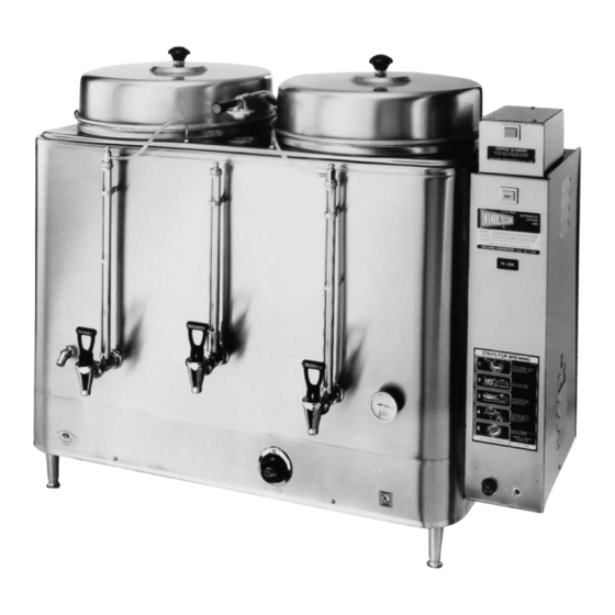
Model FE100N
Safety Information..................2
Rough-In Drawings .................3
Electrical Specifications...........5
Installation...............................5
Priming ....................................6
Operation ................................6
Thank you for purchasing this quality urn. For your safety and the safety of others, read all warnings and the
operator manual before installing or using the product. Properly instruct all operators. Keep training records. For
future reference, record serial number here:
Grindmaster-Cecilware
4003 Collins Lane, Louisville, KY 40245 USA
Phone: 502.425.4776 Toll Free: 800.695.4500
Fax: 502.425.4664
Web: gmcw.com Email: info@gmcw.com
©2018 Grindmaster-Cecilware
Printed in USA
Coffee Urns
FE75N, FE100N, FE200, FE300,
CL75N, CL100N, CL200 Series
Table of Contents
Operator Manual
Cleaning...................................7
Adjustments ............................7
Maintenance ...........................8
Parts Diagram........................12
Parts List.................................14
Wiring Diagram.....................16
Grindmaster-Cecilware
industry's BEST warranty. Visit gmcw.com
for warranty terms and conditions.
Model FE300
provides
the
0518 Form # CW-326-02
Part # 390-00070
Advertisement
Table of Contents

Summary of Contents for Grindmaster Cecilware FE75N Series
-
Page 1: Table Of Contents
Operator Manual Coffee Urns FE75N, FE100N, FE200, FE300, CL75N, CL100N, CL200 Series Activate your warranty now at http://gmcw.com/warranty-registration Model FE100N Model FE300 Table of Contents Safety Information....2 Cleaning........7 Rough-In Drawings ....3 Adjustments ......7 Electrical Specifications...5 Maintenance ......8 Installation.......5 Parts Diagram......12 Priming ........6 Parts List.........14 Operation ........6... -
Page 2: Safety Information
Safety Information Important Safety Information This is the safety alert symbol. It is used to alert you to potential personal injury hazards. Obey all safety messages that follow this symbol to avoid possible injury or death. For your safety and the safety of others, read all warnings and the operator manual before installing or using the product. -
Page 3: Rough-In Drawings
Rough-In Drawings FE75N Single 3 Gallon Urn, Adjustable By-pass, Automatic Agitator, and Solid State Timer CL75N Single 3 Gallon Urn, Adjustable By-pass, Push-Button Agitator, and Electro-Mechanical Timer 29.1 19.3 ↓ ↑ TEMPERATURE CONTROL 10.1 NN10A 16.0 14.0 FE100N Twin 3 Gallon Urn, Adjustable By-pass, Automatic Agitator, and Solid State Timer CL100N Twin 3 Gallon Urn, Adjustable By-pass, Push-Button Agitator, and Electro-Mechanical Timer 29.1 19.3... - Page 4 Rough-In Drawings (continued) FE200 Single 6 Gallon Urn, Adjustable By-pass, Automatic Agitator, and Solid State Timer CL200 Single 6 Gallon Urn, Adjustable By-pass, Push-Button Agitator, and Electro-Mechanical Timer 31.2 21.2 10.1 NN10A 32.0 16.0 FE300 Twin 10 Gallon Urn, Adjustable By-pass, Automatic Agitator, and Solid State Timer 34.5 23.4 NN10A...
-
Page 5: Electrical Specifications
Electrical Specifications Information below provided for US models only. Check rating marking on urn nameplate. Consult factory for export model information. VOLTS KILOWATTS AMPS 1 PHASE 3 PHASE 1 PHASE 3 PHASE 3 WIRE 4 WIRE 120/240 120/208 120/240 120/208 120/240 120/208 120/240... -
Page 6: Priming
Installation (continued) Priming NOTE: THERMOSTAT MUST BE IN THE "OFF" POSITION. WARNING: ELECTRIC SHOCK HAZARD! 1. Open water supply line valve to urn. Installation of this appliance should be performed by 2. Turn on or plug in the power supply to the urn. qualified service personnel only. -
Page 7: Cleaning
Cleaning CAUTION: BURN HAZARD The urn surfaces and water inside jacket are very hot. Faucet Handle Use caution when cleaning this urn to prevent burns. NOTICE: All sanitizing agents in the food zone must comply with 21 CFR 178.1010. Sanitize all food Bonnet dispensing units periodically. - Page 8 Adjustments (continued) right of side box if water gets too high. WARNING: SHOCK AND BURN HAZARD 3. If maximum setting of timer fails to deliver enough To prevent electric shock and burn hazard, all tasks water, check water pump and spray head and described in this section are to be performed by a follow instructions under Maintenance.
-
Page 9: Maintenance
Adjustments (continued) cleaning and maintenance. The swivel valve has a large WARNING: SHOCK AND BURN HAZARD flow opening and the spray head cap is equipped with To prevent electric shock and burn hazard, all tasks a stainless steel disc, used to control the flow of water. described in this section are to be performed by a When ordering replacement parts, be sure to order the trained and qualified service technician. - Page 10 Maintenance (continued) that you use a counter wrench when removing WARNING: SHOCK AND BURN HAZARD and installing pump to avoid damaging copper To prevent electric shock and burn hazard, all tasks tubing. DO NOT OVERTIGHTEN. described in this section are to be performed by a 4.
- Page 11 Maintenance (continued) 1. Turn on the power and water supply. Check inside WARNING: SHOCK AND BURN HAZARD the tank to make sure the water is below the Probe. To prevent electric shock and burn hazard, all tasks Pull the BLUE wire and terminal OFF the Probe rod. described in this section are to be performed by a 2.
-
Page 12: Parts Diagram
Parts Diagram (refer to key on page 15) Cecilware Coffee Urns ®... - Page 13 Parts Diagram (continued) (refer to key on page 15) Coffee Urns Cecilware ®...
-
Page 14: Parts List
Parts Diagram (continued) 220-00132 SIGHT GLASS GAUGE BASE (SOLD SEPARATELY) Parts List ITEM PART DESCRIPTION QUANTITY FE75N FE75N CL75N FE100N FE100N CL100N FE200 CL200 FE300 DUAL DUAL DUAL BREW BREW BREW B157A TERMINAL BLOCK 4 WIRE C036AL CONTACTOR, 3 POLE, 50 AMP - (240V) CG12AL CONTACTOR, 3 POLE, 50 AMP - (120V) C395AL... - Page 15 Parts List (continued) ITEM PART DESCRIPTION QUANTITY FE75N FE75N CL75N FE100N FE100N CL100N FE200 CL200 FE300 DUAL DUAL DUAL BREW BREW BREW E000A WATER PUMP (120V ONLY) (Prior to 3/2014) E070A WATER PUMP (240V) (Prior to 3/2014) A533-033 WATER PUMP (120V ONLY) (After 3/2014) A533-034 WATER PUMP (240V) (After 3/2014) 359-00074...
-
Page 16: Wiring Diagram
Wiring Diagram FE-N-D SERIES W/ SINGLE TIMER SWITCH CONFIGURATION DELAY Gray TIMER SINGLE BLEND TIMER Blue STOP BREW BREW LIGHT PUMP BREW SWITCH WATER INLET TANK CONTROL BOARD VALVE TRANSFORMER WATER FILL LEVEL PROBES RELAY WATER THERMISTOR CONTACTOR FUSE POWER SWITCH (N FOR 120V) Cecilware Coffee Urns... - Page 17 Wiring Diagram (continued) FE-N SERIES W/ SINGLE TIMER AIR AGITATOR PUMP Gray DELAY SWITCH TIMER CONFIGURATION Blue SINGLE BLEND TIMER Blue STOP BREW BREW LIGHT PUMP BREW SWITCH WATER INLET VALVE TANK CONTROL BOARD TRANSFORMER WATER FILL LEVEL PROBES RELAY WATER THERMISTOR CONTACTOR...
- Page 18 Wiring Diagram (continued) FE-N-D SERIES W/ DUAL TIMER SWITCH CONFIGURATION BREW LIGHT Purple DELAY Purple Gray TIMER BREW SWITCH DUAL BLEND TIMER Blue STOP HALF BREW HALF SWITCH BREW BREW PUMP LIGHT WATER INLET TANK CONTROL BOARD VALVE TRANSFORMER WATER FILL LEVEL PROBES...
- Page 19 Wiring Diagram (continued) FE-N SERIES W/ DUAL TIMER SWITCH CONFIGURATION AIR AGITATOR PUMP BREW LIGHT Purple Gray DELAY Purple TIMER BREW Blue SWITCH DUAL TIMER BLEND Blue STOP HALF BREW HALF SWITCH BREW BREW PUMP LIGHT WATER INLET VALVE TANK CONTROL BOARD TRANSFORMER WATER FILL...
- Page 20 Wiring Diagram (continued) CL-N-D SERIES SWITCH CONFIGURATION WATER INLET VALVE TANK CONTROL BOARD TRANSFORMER WATER FILL LEVEL PROBES RELAY WATER THERMISTOR CONTACTOR FUSE POWER SWITCH (N FOR 120V) Cecilware Coffee Urns ®...
- Page 21 Wiring Diagram (continued) CL-N SERIES SWITCH CONFIGURATION WATER INLET VALVE TANK CONTROL BOARD TRANSFORMER WATER FILL LEVEL PROBES RELAY WATER THERMISTOR CONTACTOR FUSE POWER SWITCH (N FOR 120V) Coffee Urns Cecilware ®...
- Page 22 Wiring Diagram (continued) CH-N-D SERIES SWITCH CONFIGURATION WATER INLET VALVE TANK CONTROL BOARD TRANSFORMER WATER FILL LEVEL PROBES RELAY WATER THERMISTOR CONTACTOR FUSE POWER SWITCH (N FOR 120V) Cecilware Coffee Urns ®...
- Page 23 Wiring Diagram (continued) AIR AGITATOR PUMP SWITCH CONFIGURATION Gray DELAY TIMER Blue SINGLE BLEND TIMER Blue STOP BREW BREW LIGHT PUMP BREW SWITCH WATER WATER LEVEL CONTROL INLET VALVE 1 FILL 2 AC-1L 3 AC-2N 4 L-LEVEL WATER 5 H-LEVEL 6 COMMON LEVEL PROBES...
- Page 24 Wiring Diagram (continued) Cecilware Coffee Urns ®...
- Page 25 Wiring Diagram (continued) Coffee Urns Cecilware ®...
- Page 26 Wiring Diagram (continued) Cecilware Coffee Urns ®...
- Page 27 Wiring Diagram (continued) Coffee Urns Cecilware ®...
- Page 28 Cecilware Coffee Urns ®...
- Page 29 Coffee Urns Cecilware ®...
- Page 30 Grindmaster-Cecilware 4003 Collins Lane, Louisville, KY 40245 USA Phone: 502.425.4776 Toll Free: 800.695.4500 Fax: 502.425.4664 Web: gmcw.com Email: info@gmcw.com 0518 Form # CW-326-02 ©2018 Grindmaster-Cecilware Part # 390-00070 Printed in USA...
Need help?
Do you have a question about the FE75N Series and is the answer not in the manual?
Questions and answers