Advertisement
Quick Links
READ AND UNDERSTAND ALL INSTRUCTIONS BEFORE BEGINNING INSTALLATION
Parts List
1-
PART NUMBER
Kit Contents:
1.
MGL-TX20 Transmitter unit
2.
MGL-RX20 Receiver unit
3.
Receiver antenna
4. (2) AA lithium batteries
5. (4) #6 pan head transmitter mounting screws
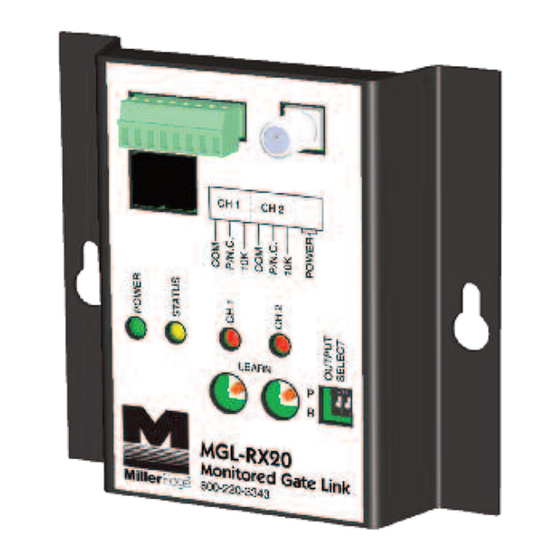
Install Receiver
2-
2-1. Mount the Receiver inside the operator cover.
2-2. Attach the antenna to the Receiver. An extension
cable will be required if the operator cover is
metal. Ideally, antenna should be vertical and in
line-of-sight of the Transmitter(s).
2-3. Connect power (12-24 VAC/DC) to the terminals
marked POWER (not polarity sensitive).
Determine which monitored interface your
operator uses. Connect the COM and the
correct output connections (P/N.C., 10K) to your
operator. The Output Select dip switch 1 is
set to "R" for all operator's requiring either a N.C.
or a 10K input, or set to "P" for operator's that
require a pulsed input. Switch 2 has no function.
2-4. Apply power to the Receiver. Observe that the
green and yellow LEDs are on. The Channel 1
red LED will blink, and the Channel 2 LED will be
on solid. After 15 seconds, the Channel 2 LED will
go out, unless there is a Transmitter associated
with it. If the yellow LED is blinking randomly, at
least one Transmitter has been Learned and is
working.
P.O. Box 159 • West Grove, PA 19390 • 800-220-3343 • 610-869-4422 • Fax: 610-869-4423 • www.milleredge.com
6809 South Harl Avenue, Suite A • Tempe, AZ 85283 • 800-887-3343 • 480-755-3565 • Fax: 480-755-3558
IMPORTANT:
Required:
1. 1/8" flat blade screwdriver
2. 1/4" flat blade screwdriver
3. 10K (T2/blue band) terminated Sensing Edge
Recommended:
• VOM for test purposes
• Mounting screws as required for receiver
Model: MGL-K20
MOUNTING
ANTENNA
TABS (2)
RECEIVER
ENCLOSURE
TERMINAL
DIAGRAM
MGL-K20_Inst_20160815
Advertisement

Summary of Contents for Miller Edge MGL-TX20
-
Page 1: Parts List
READ AND UNDERSTAND ALL INSTRUCTIONS BEFORE BEGINNING INSTALLATION Parts List PART NUMBER Kit Contents: Required: MGL-TX20 Transmitter unit 1. 1/8” flat blade screwdriver MGL-RX20 Receiver unit 2. 1/4” flat blade screwdriver 3. 10K (T2/blue band) terminated Sensing Edge Receiver antenna 4. - Page 2 Learn Mode TOP LID 3-1. Prior to mounting the Transmitter(s), remove the SCREWS cover(s) and insert the batteries, noting their polarity. The green LED should blink once every second. Press the Test button, next to the green LED, and note that the green LED flashes rapidly 3 times. 3-2.
- Page 3 Install Transmitter and Test 4-1. Strip back approximately 4 inches of outer covering of Sensing Edge cable, then feed through Transmitter strain relief fitting. Connect the two Edge wires to the removable terminal SE1 (not polarized). Dress the wires next to the battery holder and tighten the strain relief. Mount unit vertically utilizing the mounting holes at the 4 corners of the transmitter box.
-
Page 4: Fcc Compliance
7-FCC Compliance Transmitter: MODEL: MGL-TX20 FCC ID: OYE-MGL-916 THIS DEVICE COMPLIES WITH PART 15 OF THE FCC RULES. OPERATIONS IS SUBJECT TO THE FOLLOWING TWO CONDITIONS: 1) THIS DEVICE MAY NOT CAUSE HARMFUL INTERFERENCE 2) THIS DEVICE MUST ACCEPT ANY INTERFERENCE RECEIVED INCLUDING INTERFERENCE THAT MAY CAUSE UNDESIRED OPERATION.
Need help?
Do you have a question about the MGL-TX20 and is the answer not in the manual?
Questions and answers