Table of Contents
Advertisement
Quick Links
Have this manual in the palm of
your hand by FG Finder application.
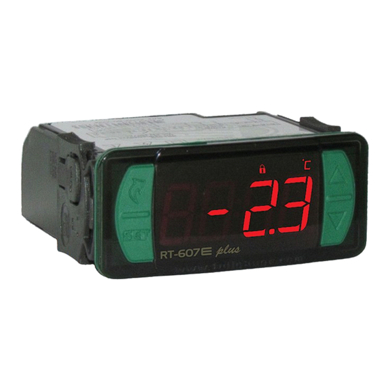
1. DESCRIPTION
Digital temperature controller and indicator combined with a time scheduler which allows the user to
configure up to eight daily events, with programmable start and end time, which may be daily, weekly or
split into business days and weekends. It allows the user to activate the load manually even out of the
events. In addition to that, it offers parameters for recirculation and protection of water heaters. With the
sensor disabled it works as a time scheduler only. It includes serial communication for connection to
Sitrad.
2. SAFETY RECOMMENDATIONS
- Check the controller for correct fastening;
- Make sure that the power supply is off and that it is not turned on during the controller installation;
- Read the present manual before installing and using the controller;
- Use adequate Personal Protective Equipmenet (PPE);
- For application at sites subject to water spills, such as refrigerated counters, install the protecting vinyl
supplied with the controller;
- For protection under more critical conditions, we recommend the Ecase cover, which we make
available as an optional item (sold separately);
- The installation procedures should be performed by a qualified technician.
3. APPLICATIONS
• Air Conditioning
• Water heaters
• Displays with static coils
• Defrost control
• Ovens, injection machines
• All processes that require time scheduling
4. TECHNICAL SPECIFICATIONS
Electric supply
Approximate consumption
Control temperature
Operating temperature
Minimum interval between events
Maximum current/power per output
Operating humidity
Dimensions (mm)
Dimensions for cutting – to fasten
the instrument
(*) Acceptable variation in relation to the rated voltage.
(**) This device can measure and control temperatures of up to 200°C when used in conjunction with a model SB59
silicon sensor cable (sold separately)
Note: Sensor cable length can be increased to up to 200 meters by the user by using a PP 2 x 24 AWG cable.
5. INDICATIONS AND KEYS
Event schedule indicator LED
Heating indication LED
Cooling indication LED
Quick access
menu key (Flatec)
Set key
e plus
RT-607
6. WIRING DIAGRAM
6.1. Identifications (see Images I to IV)
- Image I: RT-607E plus , supplied at 115 Vac.
- Image II: RT-607E plus, supplied at 230 Vac.
- Image III: RT-607EL plus, supplied at 12 Vac/dc.
- Image IV: RT-607EL plus, supplied at 24Vac/dc.
IMPORTANT
INSTRUMENTS IN THE EVOLUTION SERIES HAVE TWO DIFFERENT TERMINAL SIZES, BUT BOTH ARE
COMPATIBLE WITH THE SCREWDRIVER 2.0mm. USING THE APPROPRIATE TOOLS DURING INSTALLATION
ENSURES A LONGER LIFE AND THE PROPER OPERATION OF THE PRODUCTS.
RT-607
DIGITAL THERMOSTAT WITH
EVENT SCHEDULE
Functions
Control
Event
Lock
Functions
Schedule
Shutdown
RT-607E plus: 115 or 230 Vac ±10%(*) (50/60 Hz)
RT-607EL plus: 12 or 24 Vac/dc +10%(*)
0.7 VA
-50 to 105ºC (-58 to 221°F)(**)
0 to 50 ºC / 32 to 122°F
10 minutes
THERM - Thermostat control output:
16(12)A 250Vac 2HP
EVENT - Event schedule activation output:
10A / 240Vac ¼ HP
10 to 90% RH (no condensation)
76 x 34 x 77 mm (WxHxD)
71 ± 0,5 x 29 ± 0,5 mm (see image V)
Functions lock indication LED
Control functions off indication LED
Temperature unit indication LED
e plus
IP 65
FRONT
Supervisory
Serial
Protection
system
programming
level
Image I: RT-607E plus - 115Vac
SITRAD
A
B
5 6 7 8
1
2 3 4
Image II: RT-607E plus - 230 Vac
SITRAD
A
B
5 6 7 8
1
2 3 4
Image III: RT-607EL plus - 12Vac/dc
SITRAD
A
B
5 6 7 8
1
2 3 4
Image IV: RT-607EL plus - 24Vac/dc
SITRAD
A
B
5 6 7 8
1
2 3 4
Increase key
Decrease key
Surge Protective Device (SPD) (sold separately)
W i r i n g d i a g r a m f o r
instalation of SPD in
magnectic contactor
A1 and A2 are the terminals
of the contactor coil.
6.2. Temperature sensor connection
- Connect the sensor wires to terminals '1 and 2': the polarity is not relevant.
- Length of the sensor cables can be increased by user himself to up to 200 meters, using a PP 2x24
AWG cable.
e pl us
e pl us
RT -6 07
RT -6 07
D1
9 10 11 12 13 14 15 16 17
D1
9 10 11 12 13 14 15 16 17
D1
9 10 11 12 13 14 15 16 17
0
12Vac/dc
D1
9 10 11 12 13 14 15 16 17
0
24Vac/dc
W i r i n g d i a g r a m f o r
instalation of SPD in line
A1
with loads
For direct drive take in to
consideration the specified
A2
maximum current.
evolution
115 Vac
230 Vac
Power supply
Power supply
LOAD
Advertisement
Table of Contents

Related Manuals for Full Gauge RT-607e plus


Summary of Contents for Full Gauge RT-607e plus
- Page 1 LOAD magnectic contactor For direct drive take in to - Image I: RT-607E plus , supplied at 115 Vac. A1 and A2 are the terminals consideration the specified - Image II: RT-607E plus, supplied at 230 Vac. of the contactor coil.
- Page 2 Use the pins according to table below, considering the set version: the setpoint and other parameters can be visible to the user, but are protected against undue changes Pins RT-607E plus RT-607EL plus [,f15]= 2 or you can block changes of control functions and leave the adjustment of the setpoint...
- Page 3 8.3.8. Event schedule programming 8.5. Parameters table This option allows entering the values of the time intervals for each event. Data input depends on the CELSIUS FAHRENHEIT configured operation mode. Up to eight events may be configured for each day. The start time and end Description time of each event is set using options[,OnI]to [,On8][Off8], where: Unit...
- Page 4 TTL Serial connection. EASYPROG [ALrM] Alarm for failure to reach the setpoint. IMPORTANT TO PERFORM THE COMMUNICATION [eCAL] Contact Full Gauge Controls. WITH EASYPROG THIS EQUIPMENT MUST NOT BE COMMUNICATING WITH SITRAD SOFTWARE. [pppp] Reconfigure the values of the functions.
- Page 5 13. ANNEXES - Reference Images ENVIRONMENTAL INFORMATION Packaging: Image V The materials used in the packaging of Full Gauge products are 100% recyclable. Try to perform disposal through specialized recyclers. Product: The components used in Full Gauge controllers can be recycled and reused if disassembled by specialized companies.
Need help?
Do you have a question about the RT-607e plus and is the answer not in the manual?
Questions and answers