Table of Contents
Advertisement
TRIGNO Wireless System
User's Guide
TM
September 2012 Edition
PM-W01
Copyright © 2012 by Delsys Incorporated
Specifications and procedures outlined in
this document are subject to change
without notice.
Delsys Logo, EMGworks, and Myomonitor
are Registered Trademarks of Delsys
Incorporated.
MAN-012-2-4
Advertisement
Table of Contents

Related Manuals for Delsys Tringo

Summary of Contents for Delsys Tringo
- Page 1 TRIGNO Wireless System User’s Guide September 2012 Edition PM-W01 Copyright © 2012 by Delsys Incorporated Specifications and procedures outlined in this document are subject to change without notice. Delsys Logo, EMGworks, and Myomonitor are Registered Trademarks of Delsys Incorporated. MAN-012-2-4...
-
Page 3: Table Of Contents
Table of Contents Table of Contents ............... 3 Important Information ..............5 Intended Use................ 5 Contraindications ..............5 Technical Service and Support ..........5 Warnings and Precautions ........... 6 Device Information ............... 7 Disclaimer ................9 Limited Warranty ..............9 System Requirements............ - Page 4 Trigno System Settings ............25 Mode Control (Analog Output Software Only) ....26 Test Panel ................26 Additional Sensor Information ..........28 Sensor Pairing ..............28 Sensor Factory Calibration ..........29 Smart Sensors ..............30 Sensor Modes in EMGworks ..........30 Using Tandem Trigno Systems ..........
-
Page 5: Important Information
Intended Use The Trigno Wireless EMG Systems are battery-powered biofeed- back devices intended for research, investigational and scholarship purposes only. Delsys products are not intended for measurement ® purposes or for use in the treatment and diagnosis of disease. Inter- pretation of the EMG signal by a qualified professional is required. -
Page 6: Warnings And Precautions
Connect only to Delsys-approved devices. Connecting a patient to high-frequency surgical equipment while using Delsys EMG systems may result in burns at the site of the EMG sensor contacts. Immediately discontinue device use if skin irritation or discomfort occurs. -
Page 7: Device Information
93/42/EEC. Class I device, Annex VII. Type BF device (IEC 60601-1) Isolated device, (Class II, IEC 60601-1) Do not dispose this product with house waste. Contact Delsys Inc. for instructions on responsibly disposing this device. This product should not be mixed with other commercial wastes. - Page 8 Changes not expressly approved by Delsys Inc.could void the User’s authority to operate the equipment To reduce potential radio interference to other users, the antenna type and its gain should be so chosen that the equivalent isotropically radi- ated power (EIRP) is not more than that required for successful com- munication.
-
Page 9: Disclaimer
Disclaimer DELSYS INC. makes no warranties, express or implied, as to the quality and performance of this product including but not limited to, any implied warranty of applicability for other than research uses by qualified individuals. DELSYS INC. shall not be liable to... -
Page 10: Trignotm Wireless Emg System Overview
Trigno Wireless EMG System Overview The Trigno Wireless EMG System is a high-performing device unparalleled in its sophistication, its reliability and its ease-of-use. Each EMG sensor has a built-in triaxial accelerometer, a guaranteed transmission range of 40 m and a rechargeable battery lasting a minimum of 7 hours. -
Page 11: Sensor Led Indicator Status
Sensor LED Indicator Status Status LED Behavior Data Streaming Flashing green, 1 Hz Scanning Alternating green/amber flash, 1Hz Pairing Successful Rapid green flashing, 3x, button depressed Pairing Unsuccessful Rapid red flashing, 3x, button depressed Mode Switch Rapid green flashing, 3x Firmware Update Rapid green flashing, 3x Battery Charging... -
Page 12: Power Supply
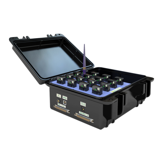
Power Supply Trigno Systems are equipped with an isolated medical grade power supply. The green power LED on the base station will illuminate when power is connected to the Base Station. The power supply is provided with interchangeable country-specific plug adapters. The power supply can be conveniently stored in the Base Station storage space when the system is not in use. -
Page 13: Getting Started With The Trignotm System
Base Station to the PC. If not, the “Found New Hardware” dialog will appear and Windows will prompt for a driver location. Cancel this dialog and install EMGworks from the Delsys DVD in order to register the Trigno drivers with the operating system. -
Page 14: Charging The Sensors
Once the software is correctly installed, the PC will automatically detect the Trigno Base Station when connected to the USB port. Charging the Sensors Before using the system, the sensors should be fully charged by placing them in the Base Station cradle slots. Ensure the Base Sta- tion is powered and that the green power LED is illuminated. -
Page 15: Acquiring Data In Emgworks Acquisition
Acquiring Data in EMGworks Acquisition Refer to the “Acquiring and Plotting Data” video tutorial (provided on the DVD) for a brief introduction to configuring the EMGworks software with the Trigno system. This and additional EMGworks tutorials can be found on our website. Refer to the EMGworks documentation (accessible in the Help menu of the software) for detailed instructions on setting up data collection in EMGworks. -
Page 16: Using The Wireless Emg Sensors
The sensor is easily attached to the skin using the Delsys Adhesive Sensor Interface. muscle-fiber direction Figure 6. EMG Sensors must be properly oriented with the muscle fibers. Align the sensor’s arrow with the direction of the underlying muscle fibers. -
Page 17: Turning The Sensors On
skin, minimizing motion artifacts and the ill-effects of line interference. To ensure a strong bond with the skin, it is advised to remove excessive hair and wipe the skin area and the EMG Sensor with isopropyl alcohol to remove oils and surface residues. Allow the skin to dry completely before applying the interfaces. -
Page 18: Turning The Sensors Off
hosts the sensor pairing function and can send an “off” command to all sensors. A compact display of this information is accessible in EMGworks by hovering over the notification area icon for the Trigno hardware. The full dialog is displayed by double-slicking this icon. Figure 8. -
Page 19: Using The Analog Outputs
Using the Analog Outputs The Trigno System provides simultaneous analog signal reconstruction of data being detected by all active sensors. These signals are made available on the 68-pin connectors located on the Base Station. EMG signals at these outputs are amplified by a factor of 909, with full dynamic range of 5V. -
Page 20: Screw Terminal Connections
Screw Terminal Connections Many data acquisition systems are equipped with screw-type wire terminations. In these cases Delsys can supply a cable assembly that mates with the analog output connectors and breaks out the individual channels onto single conductors. Please contact Delsys for details regarding this particular wire assembly or other connectivity needs. -
Page 21: Trigno Control Utility Software
Launching the Software When installed, the Trigno Control Utility software may be launched from the Start menu under “Delsys, Inc.” To create a desktop shortcut to the Trigno Control Utility, navigate to the program in the Start menu, right click the icon, and select “Send To -->... - Page 22 Figure 12. Trigno Control Utility software. Figure 13. Trigno Control Utility software with active outputs Trigno Wireless System User’s Guide...
-
Page 23: Configuration Options For Trigno System
Configuration Options for Trigno System Accessing Configuration Options When editing a configuration in EMGworks, the hardware options for the base station can be set in the Hardware node of the Configuration Tree when the Trigno Wireless System is selected as the primary A/D device. -
Page 24: Trigno System Information
Four frequency sets are available (“A”, “B”, “C” and “D”). The current frequency set is shown here. Firmware Version Delsys may occasionally release firmware upgrades to improve and evolve the functionality of Trigno Systems. The current firmware version is shown here. -
Page 25: Trigno System Settings
produce a unique sinusoid which can be verified by properly sampling these channels with secondary acquisition system. Refresh This button refreshes the status information. Copy Copies the data the in the Information tab to the clipboard. Trigno System Settings The Settings tab allows several system parameters to be modified as needed. -
Page 26: Mode Control (Analog Output Software Only)
Mode Control tab of the Configuration dialog. Information on mode control is available through our EMGworks online help: http://www.delsys.com/Products/EMGworks.html Test Panel The Test Panel is used to verify the analog signal connections with the data acquisition module by outputting predefined and unique signals on each channel. - Page 27 expected outputs for each analog channels are listed in the Test Panel window once the option is slected. Figure 18. The Test Panel Signals.
-
Page 28: Additional Sensor Information
Additional Sensor Information Sensor Pairing Trigno sensors communicate with a custom wireless protocol that links each sensor to a unique Base Station. This linking process is known as sensor “pairing”, and is initiated through the “Pair” command. Trigno systems are shipped with all sensors appropriately paired. Sensor pairing is typically needed if sensors are being replaced within the network group, when the communication frequency sets are changed, and after a firmware upgrade is performed. -
Page 29: Sensor Factory Calibration
Delsys. Factory calibration data are a string of numbers and letters which encode the calibration values for a specific sensor. -
Page 30: Smart Sensors
Smart Sensors After pairing, the association of sensors to the base station is retained for all future uses. Any configuration in EMGworks can be made to reflect the last paired set of sensors by clicking the “Refresh Smart Sensors” button in the “Add Sensors” pane in EMGworks. -
Page 31: Using Tandem Trigno Systems
Using Tandem Trigno Systems Two Trigno systems may be used in tandem, connected to the same computer as a synchronized 32 sensor, 128 channel system. Initial Connectivity To use two Trigno systems in a tandem configuration, connect the USB cable from each base station to the same computer. If using EMGworks, also connect the Trigger Cross-Over Cable (DC-C02) between the trigger ports on the two base stations. -
Page 32: User Interface
User Interface User interface options are expanded to reflect the presence of additional sensors. Figure 26. The Status Console when tandem bases are used. Trigno Wireless System User’s Guide... -
Page 33: Maintenance And Care
Maintenance and Care Trigno Sensors Trigno sensor are encased in a sealed polycarbonate enclosure. The following points should be kept in mind when handling the sensors. • All sensors should be visually inspected before each use to ensure that no mechanical deterioration has occurred. •... - Page 34 • The units are not shockproof and should not be dropped or be subjected to excessive forces or accelerations. The recharging Base Station is not water-resistant. Under no circumstance should this unit be exposed to water or any other type of liquids. Trigno Wireless System User’s Guide...
-
Page 35: Specifications
Specifications Trigno Sensors GENERAL SPECIFICATIONS Typical Operating Range 40 m RF Frequency Band 2400-2480 MHz (ISM band) Power Consumption <65 mW Case Dimension 27 x 37 x 15 mm 8 hours Full-charge Operation Time <2.5 hours Recharge Time Mass < 15g Auto Shut-down timer 300 seconds Temperature Range... - Page 36 EMG SENSOR SPECIFICATIONS Contact Dimension 5 x 1 mm. 99.9% Silver Contact Material Range is specified for the input of the EMG sensor and is samples with 16 bits ADC Resolution is specified for the input of the sensor. Filter is designed as a maximally flat Butterworth to preserve EMG signal amplitude and phase linearity.
-
Page 37: Trigno Recharging Base Station
Trigno Recharging Base Station GENERAL SPECIFICATIONS Typical Operating Range 40 m RF Frequency Band 2400-2480 MHz (ISM) <6 W (operation) Power Consumption <14W (during recharge) Sensor Recharge Time < 2.5 hours USB type USB 2.0 compliant, high speed Temperature Range 5 - 50 degrees Celsius Maximum number of Sensors Inter-sensor delay... - Page 38 ACCELEROMTER ANALOG OUTPUT SPECIFICATIONS 16 X Axis Number of outputs 16 Y Axis 16 Z Axis 96 ms Signal group delay Accelerometer Output Signal Range ±5 V Nominal Accelerometer Signal 2.424 V/g ±5% (±1.5g range) 0.624 V/g ±5% (±6g range) Gain Channel Offset ±100 mV (max)
-
Page 39: Mains Isolation
PC running the Trigno Software is conceivably within their reach, it too must be isolated. Delsys does not supply isolation transformers for Personal Computers and their peripherals. Delsys recommends model IS1000HG manufactured by Tripp Lite (www.tripplite.com) for this task. -
Page 40: Dc-A22 Unterminated Output Cable
Appendix II DC-A22 Unterminated Output Cable The DC-A22 Unterminated Output Cable provides access to all 64 analog output channels from the Trigno System on discrete wires for data acquisition systems with screw-type terminations. The DC-A22 cable connects directly to the output connector labeled "1-64"on the Trigno System and terminates in 67 signal conductors with pre-stripped ends (64 analog output signals and 3 GND conductors). -
Page 41: Dc-A22 Conductor Assignments
DC-A22 Conductor Assignments Trigno Trigno Conductor Color Trigno Trigno Conductor Color Output Primary / Secondary Output Primary / Secondary EMG 1 Violet / Orange AY 9 Tan / Violet AX 1 Blue / Orange AZ 9 Tan / Gray AY 1 Orange / Blue EMG 10 Blue / Tan... - Page 42 Trigno Wireless System User’s Guide...
Need help?
Do you have a question about the Tringo and is the answer not in the manual?
Questions and answers