Table of Contents
Advertisement
Quick Links
™
RACAL INSTRUMENTS
1260-164 AH/BH
SP4T MICROWAVE
SWITCH PLUG-IN
Publication No. 980824-164AH/BH Rev. A
Astronics Test Systems Inc.
4 Goodyear, Irvine, CA 92618
Tel: (800) 722-2528, (949) 859-8999; Fax: (949) 859-7139
atsinfo@astronics.com
atssales@astronics.com
atshelpdesk@astronics.com
http://www.astronicstestsystems.com
Copyright 2015 by Astronics Test Systems Inc. Printed in the United States of America. All rights reserved.
This book or parts thereof may not be reproduced in any form without written permission of the publisher.
Advertisement
Table of Contents

Subscribe to Our Youtube Channel
Summary of Contents for Astronics RACAL INSTRUMENTS 1260-164AH
- Page 1 Tel: (800) 722-2528, (949) 859-8999; Fax: (949) 859-7139 atsinfo@astronics.com atssales@astronics.com atshelpdesk@astronics.com http://www.astronicstestsystems.com Copyright 2015 by Astronics Test Systems Inc. Printed in the United States of America. All rights reserved. This book or parts thereof may not be reproduced in any form without written permission of the publisher.
- Page 2 THANK YOU FOR PURCHASING THIS ASTRONICS TEST SYSTEMS PRODUCT For this product, or any other Astronics Test Systems product that incorporates software drivers, you may access our web site to verify and/or download the latest driver versions. The web address for driver downloads is: http://www.astronicstestsystems.com/support/downloads...
- Page 3 This document and the technical data herein disclosed, are proprietary to Astronics Test Systems, and shall not, without express written permission of Astronics Test Systems, be used in whole or in part to solicit quotations from a competitive source or used for manufacture by anyone other than Astronics Test Systems.
- Page 4 FOR YOUR SAFETY Before undertaking any troubleshooting, maintenance or exploratory procedure, read carefully the WARNINGS and CAUTION notices. This equipment contains voltage hazardous to human life and safety, and is capable of inflicting personal injury. If this instrument is to be powered from the AC line (mains) through an autotransformer, ensure the common connector is connected to the neutral (earth pole) of the power supply.
- Page 6 This page was left intentionally blank.
-
Page 7: Table Of Contents
Front Panel Connectors 1260-164AH ..................2-2 Front Panel Connectors 1260-164BH ..................2-4 Mating Connectors ......................... 2-6 Chapter 3 ....................... 3-1 MODULE OPERATION ..................3-1 Reply to the MOD:LIST? Command ..................3-1 Operating in Register-Based Mode .................... 3-2 1260-164 Example Code ....................... 3-6 Astronics Test Systems... - Page 8 1260-164AH/BH User Manual Publication No. 980824-164AH/BH Rev. A This page was left intentionally blank. Astronics Test Systems...
- Page 9 Table 3-2, ID Register Functionality of the 1260-164..............3-3 Table 3-3, Port A Register Functionality of the 1260-164 Module ..........3-4 Table 3-4, Port B Register Functionality of the 1260-164 Module ..........3-4 Table 3-5, EPROM Descriptor Functionality of the 1260-164 Module ..........3-5 Astronics Test Systems...
- Page 10 1260-164AH/BH User Manual Publication No. 980824-164AH/BH Rev. A DOCUMENT CHANGE HISTORY Revision Date Description of Change 8/6/2015 Initial release Admin. No revision roll. ECN06381. Adds CE 8/18/2015 certificate. Astronics Test Systems...
-
Page 11: Chapter 1
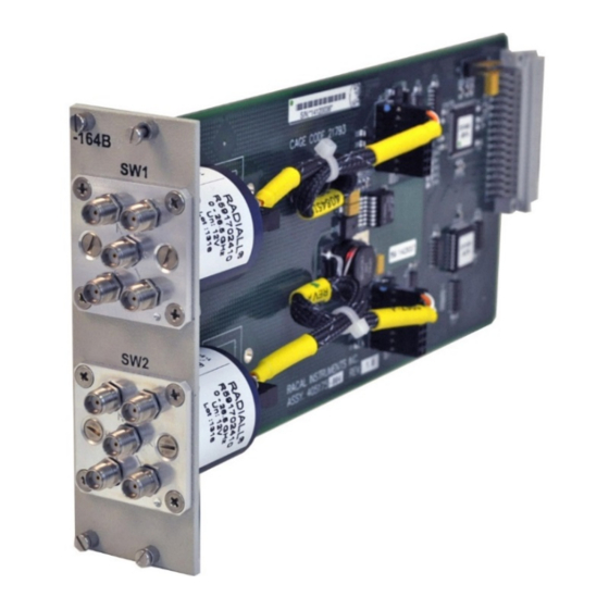
Standard Adapt-a-Switch and 1256 Switching System plug-in design, providing for ease of replacement. • Data-Driven embedded descriptor, allowing immediate use with any platform compatible with the Adapt-a-Switch standard, regardless of firmware level. Figure 1-1, 1260-164BH Astronics Test Systems Specifications 1-1... -
Page 12: Specifications - 1260-164Ah/Bh
+5 VDC Amps Maximum 1260-164BH 1.95 A Weight 1260-164AH 5.8 oz, 164 gm 1260-164BH 8.0 oz, 227 gm 1260-164AH 860,000 hrs Mean Time Between Failures (MTBF) 1260-164BH 560,000 hrs Mean Time to Repair < 5 minutes (MTTR) Specifications 1-2 Astronics Test Systems... -
Page 13: Power Dissipation - 1260-164Ah/Bh
If one additional module is likewise loaded, then the overall carrier dissipation is approximately 7.5 W for the –164AH and 15 W for the –164BH, both of which are well within the cooling available in most commercial VXIbus chassis. Astronics Test Systems Specifications 1-3... -
Page 14: Ordering Information
Switch Module Consists of: P/N 405175-003 PCB Assy P/N 980824-164AH/BH Manual 1260-164BH Dual SP4T RF Switch Module, 2 SP4T DC-26.5 GHz 408598-002 Switch Module Consists of: P/N 405175-004 PCB Assy P/N 980824-164AH/BH Manual Additional Manual 980824-164AH/BH Specifications 1-4 Astronics Test Systems... -
Page 15: Chapter 2
VXI chassis. 3. The 1260-164 module is shipped in an anti-static bag to prevent electrostatic damage to the module. Do not remove the module from the anti-static bag unless it is in a static-controlled area. Astronics Test Systems Installation Instructions 2-1... -
Page 16: Installation
For instructions on installing the 1260-164 into a switching platform, refer to the user manual for that platform, in the “Getting Started” chapter under the “Inserting and Removing Plug-ins” section. Manuals are available at the Astronics Test Systems website: www.astronicstestsystems.com. Module... -
Page 17: Figure 2-2, 1260-164Ah Relay Diagram
Publication No. 980824-164AH/BH Rev. A 1260-164AH/BH User Manual Channel Front Panel Number Designation Figure 2-2, 1260-164AH Relay Diagram Figure 2-3, 1260-164AH Block Diagram Astronics Test Systems Installation Instructions 2-3... -
Page 18: Front Panel Connectors 1260-164Bh
SW2, with 5 SMA connectors each. See Figure 2-4 for SMA Connectors 1260- connector designations. See Figure 2-5 for the relay diagram and 164BH Figure 2-6 for a block diagram of 1260-164BH. See page 2-6 for torque requirements. Figure 2-4, 1260-164BH SMA Connector Designations Installation Instructions 2-4 Astronics Test Systems... -
Page 19: Figure 2-5, 1260-164Bh Relay Diagram
Publication No. 980824-164AH/BH Rev. A 1260-164AH/BH User Manual Channel Front Panel Channel Front Panel Designation Number Designation Number Figure 2-5, 1260-164BH Relay Diagram Figure 2-6, 1260-164BH Block Diagram Astronics Test Systems Installation Instructions 2-5... -
Page 20: Mating Connectors
It is highly recommended that a torque wrench (Ma-Com P/N 2098-5065-54 or equivalent) be used to torque the SMA connectors. A ¼-inch drive deep slotted socket, P/N 456890, is available for installation and removal of connectors. Installation Instructions 2-6 Astronics Test Systems... -
Page 21: Chapter 3
For the two SP4T switch (1260-164BH), the string value is: 1260-164B DUAL SP4T RF SWITCHING MODULE Thus, for a 1260-164AH whose module address is 2, the reply to this query would be: 2 : 1260-164A SINGLE SP4T RF SWITCHING MODULE Astronics Test Systems Module Operation 3-1... -
Page 22: Operating In Register-Based Mode
205C01 Port A read or written at this location 205E01 ID register read at this location Before explaining the particulars of reading and writing to port and Module Operation 3-2 Astronics Test Systems... -
Page 23: Table 3-1, Register Offset Addresses Of The 1260-164 Module
0x01 Port B 0x03 0x03 Read Only 0x201 EPROM Descriptor Read Only 0x203 Table 3-2, ID Register Functionality of the 1260-164 ID Register Register Table Module Version Functionality Description Always Reads 0x00 (Read Only) Astronics Test Systems Module Operation 3-3... -
Page 24: Table 3-3, Port A Register Functionality Of The 1260-164 Module
Relay SW2-2 (0: switch open 1: switch closed) -164BH only Relay SW2-3 (0: switch open 1: switch closed) Relay SW2-4 (0: switch open 1: switch closed) (not used) (not used) (not used) (not used) Module Operation 3-4 Astronics Test Systems... -
Page 25: Table 3-5, Eprom Descriptor Functionality Of The 1260-164 Module
8-bit byte to a control register, while viIn8() is used to read a single 8-bit byte from the control register. The following code example shows the use of viOut8() to update the 1260-164 module. Astronics Test Systems Module Operation 3-5... -
Page 26: 1260-164 Example Code
/* form the offset for control register 0 */ /* note that the base A24 Address for the 1260-01T */ /* is already accounted for by VISA calls viIn8() and */ /* viOut8() */ Module Operation 3-6 Astronics Test Systems... - Page 27 = viOut8 (vi, VI_A24_SPACE, offset, DATA_ITEM); if (error < 0) return( error ); /* close the VISA session */ error = viClose( hdl1260 ); if (error < 0) { /* error handling code goes here */ Astronics Test Systems Module Operation 3-7...
- Page 28 1260-164AH/BH User Manual Publication No. 980824-164AH/BH Rev. A This page was left intentionally blank. Module Operation 3-8 Astronics Test Systems...
Need help?
Do you have a question about the RACAL INSTRUMENTS 1260-164AH and is the answer not in the manual?
Questions and answers