Table of Contents
Advertisement
Advertisement
Table of Contents

Summary of Contents for Hydra Kool KGH Series
- Page 1 Compliant...
- Page 2 MVP GROUP CORPORATION 5659 Royalmount Ave. Montreal, QC, Canada H4P 2P9 Telephone: (514) 737-9701 Toll Free Telephone: (888) 275-4538 Fax: (514) 342-3854 Toll Free Fax: (877) 453-8832 Email: sales@mvpgroupcorp.com Website: www.mvpgroupcorp.com...
-
Page 3: Table Of Contents
1 General information 1.1 Case description 2 Getting started with your KGH series 2.1 Location 2.2 Uncrating 2.2.1 Front and sides assemblies 2.3 Check for damage 2.4 Control panel and main features 2.5 Check serial, model numbers and requested options 2.6 Warning/Caution labels... - Page 4 This page has been left blank intentionally.
-
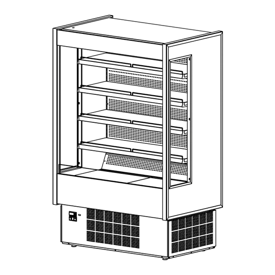
Page 5: General Information
1 General information 1.1 Case description KGH series model (number) system. KGH OF 40 S AAA BB CC D Basic model Model variation Length Type of Unit. OF-Open front 40'' S-Self Contained R-Remote FD-Front doors 50'' OS-Open front slim line... - Page 6 KGH SERIES KGH-OF-S(R) KGH-OF-S(R)
- Page 7 KGH-FD-S(R) KGH-FD-S(R)
- Page 8 KGH-OS-S(R) KGH-OS-S(R)
- Page 9 KGH-DS-S(R) KGH-DS-S(R)
- Page 10 KGH-ES-S(R) KGH-ES-S(R)
- Page 11 KGH-MS-S(R) KGH-MS-S(R)
- Page 12 Implantation Drain outlet Electrical board Refrigeration piping KGH-OF-40-S...
- Page 13 KGH-OF-40-R...
- Page 14 KGH-OF-50-S...
- Page 15 KGH-OF-50-R...
- Page 16 KGH-OF-60-S...
- Page 17 KGH-OF-60-R...
- Page 18 KGH-OF-80-S...
- Page 19 KGH-OF-80-R...
- Page 20 Implantation Drain outlet Electrical board Refrigeration piping KGH-FD-40-S...
- Page 21 KGH-FD-40-R...
- Page 22 KGH-FD-50-S...
- Page 23 KGH-FD-50-R...
- Page 24 KGH-FD-60-S...
- Page 25 KGH-FD-60-R...
- Page 26 KGH-FD-80-S...
- Page 27 KGH-FD-80-R...
- Page 28 Implantation Drain outlet Electrical board Refrigeration piping KGH-OS-40-S...
- Page 29 KGH-OS-40-R...
- Page 30 KGH-OS-50-S...
- Page 31 KGH-OS-50-R...
- Page 32 KGH-OS-60-S...
- Page 33 KGH-OS-60-R...
- Page 34 Implantation Drain outlet Electrical board Refrigeration piping KGH-DS-40-S...
- Page 35 KGH-DS-40-R...
- Page 36 KGH-DS-50-S...
- Page 37 KGH-DS-50-R...
- Page 38 KGH-DS-60-S...
- Page 39 KGH-DS-60-R...
- Page 40 Implantation Drain outlet Electrical board Refrigeration piping KGH-ES-40-S...
- Page 41 KGH-ES-40-R...
- Page 42 KGH-ES-50-S...
- Page 43 KGH-ES-50-R...
- Page 44 KGH-ES-60-S...
- Page 45 KGH-ES-60-R...
- Page 46 KGH-ES-80-S...
- Page 47 KGH-ES-80-R...
- Page 48 Implantation Drain outlet Electrical board Refrigeration piping KGH-MS-40-S...
- Page 49 KGH-MS-40-R...
- Page 50 KGH-MS-50-S...
- Page 51 KGH-MS-50-R...
- Page 52 KGH-MS-60-S...
- Page 53 KGH-MS-60-R...
- Page 54 KGH series intended for multipurpose are type 1 equipment - 75°F/55%RH. Temperature for open front cases is set for 36°F. Temperature for door cases is set for 32°F. The shelves have a 31 lb/ft2 loading limit. KGH-OF-30-S(R) 2815⁄16'' x 311⁄2'' x 767⁄8'' 2815⁄16'' x 439⁄16'' x 767⁄8''...
-
Page 55: Getting Started With Your Kgh Series
2 Getting started with your KGH series 2.1 Location To your new equipment perform well please respect the following warnings: This is type 1 equipment, inte nded to work with 75°F / 55%RH. This equipment is intended for maintaining temperature only. -
Page 57: Check For Damage
2.2.1 Shelf and product stopper assembly 4x - PRT01M04130 2.3 Check for damage At the end of production HYDRA KOOL products are carefully inspected. No damaged units are sent out. HYDRA KOOL doesn’t take responsibility for damage between factory and client. -
Page 58: Control Panel And Main Features
2.4 Control panel and main features The pictures below, shows the main features and all necessary controls Hot key connector Electronic controller Light switch Power signal Condensing unit switch Electrical board Self contained control panel (KGH-OF/FD/OS/DS/MS) Hot key connector Electronic controller Light switch Power signal Condensing unit switch... - Page 59 Electrical board Self contained control panel (KGH-ES) Hot key connector Electronic controller Light switch Power signal Condensing unit switch Electrical board Remote control panel (KGH-OF/FD/OS/DS/MS)
- Page 60 Hot key connector Electronic controller Light switch Power signal Condensing unit switch Electrical board Remote control panel (KGH-ES)
-
Page 61: Check Serial, Model Numbers And Requested Options
Return air grille Discharge air grille Hinged doors Night curtain Shutter 2.5 Check serial, model numbers and requested options Before start your equipment, check the serial number, model numbers and requested options. This inspection should be made visually in the following items:... - Page 62 Self contained numbers Remote numbers...
-
Page 63: Warning/Caution Labels
2.6 Warning/Caution labels Before starting, HYDRA KOOL products have caution and warning labels to be respected. Self contained labels Label 5 Label 6 Label 9 Label 10 Remote labels Label 9 Label 10... - Page 64 Self contained labels Label 1 Label 9 Label 11 Label 16 Label 12 Label 10 Label 2 Remote labels Label 15 Label 16 Self contained labels (Shutter rails) Label 7 Label 8...
- Page 65 Self contained and Remote labels Label 3 Label 4 Self contained and Remote labels (evaporator) Label 13 Label 14...
- Page 66 Label 1 Label 2 CAUTION ATTENTION MOVING PARTS. PIÈCES MOBILES. DO NOT OPERATE UNIT NE FAIRE PAS WITH (PART) REMOVED FONCTIONNER AVEC DES PIÈCES ENLEVER Label 3 Label 4 -NOTE- -NOTE- CETTE VITRINE TYPE 1 EST TYPE 1 EQUIPMENT - AMBIENT CONÇUE POUR FONCTION- LOCATION MUST NOT EXCEED 75 NER SELON LES CONDITIONS...
- Page 67 Label 9 Label 10 ATTENTION CAUTION RISQUE DE CHOC RISK OF ELECTRIC SHOK. ELECTRIQUE. DISCONNECT ALL AVANT TOUT TRAVAIL POWER BEFORE COUPER LE COURANT SERVICING UNIT Label 11 Label 12 CAUTION ATTENTION HOT PARTS. PIÈCES BRULANTES. DO NOT OPERATE UNIT NE FAIRE PAS WITH (PART) REMOVED FONCTIONNER AVEC LES...
-
Page 68: Check Your Electrical Installation
2.7 Check your electrical installation This equipment can be connected to an outlet with 115V/ 60Hz/ 1 phase or 220V/ 60Hz/ 1 phase. For the wright connection check tension and frequency stated in the marking plate. Nema-5-15P Nema-5-20P 2.8 Electrical, drain and refrigeration connections (remotes only) Installation and service must be performed by a qualified technician. -
Page 69: Joining
2.9 Joining For joining follow the steps described. - Page 70 3x - PAR00601011 DIN933 M6x65 8x - ANL00601002 8x - PAR00601007 DIN933 M6x20 14x- ANL00501006 DIN9021 M6 11x - PRC00101006 DIN934 M6 1⁄2 2X FIT00000316 A100 04 (298...
- Page 71 2x KGH-OF KIT0001U01000...
- Page 73 2X - FIT00000427 (9149⁄64")
- Page 74 1x - DIN933 M6x20 2x - DIN9021 M6 1x - DIN934 M6 1x - DIN933 M6x80 2x - DIN9021 M6 1x - DIN934 M6...
-
Page 75: Plugging And Start
2.10 Plugging and start To start your equipment follow the steps: 1 - Check for page with parameters inside the manual. 2 - After uncrating and placed the equipment respecting all warnings set in 2.1 chapter, and all switches are set to off position, connect the equipment. Make sure you have the correct outlet! Nema-5-15P... - Page 76 Nema-5-20P 3 - Check lights, using button referenced on chapter 2.4. If not working consult the maintenance chapter. KGH-OF/FD/OS/MS only. 3.1 - For KGH-ES, lights and shutter are controlled by key referenced on 2.4 chapter. Turn the key to check lights and shutter. (Open shutter = lights ON) Open or close shutter only when needed to prevent motor burning.
- Page 77 6 - Check for air movement in the discharge grille. 7 - Before loading, leave the equipment working for about 2h. 8 - Load your KGH-Series. Loading must be done respecting loading limits and weight per square foot mentioned in page xx. This equipment is intended for maintaining temperature, be sure the products are cold, and not ambient temperature.
-
Page 78: Refrigeration
After loading check for any obstruction in the discharge and return air grilles. Maintain doors closed after loading (KGH-FD/DS models only). 9 - If any problem encountered, see troubleshooting or call a qualified technician! 10- To fully disconnect the unit must pull the plug. 3 Refrigeration 3.1 Self contained refrigeration equipment and defrost The refrigeration equipment it’s laid out in the base of the equipment. - Page 79 Filter Evap pan Condenser Compressor Controller...
- Page 80 All self contained KGH series use the following equipment: capillary tube, finned coil ventilated systems (condenser/evaporator), hermetic compressor, electrical water evaporation system . High side Low side KGH-OF/ES/MS-30-S R 404A xx Automatic 4/day Automatic 4/day KGH-OF/ES/MS-40-S R 404A xx KGH-OF/ES/MS-50-S...
-
Page 81: Refrigeration Loads (Remotes Only)
3.2 Refrigeration loads (remotes only) Installation of remote equipment must be done by a qualified technician KGH-OF/ES/MS-30-R 4793 KGH-OF/ES/MS-40-R 6940 KGH-OF/ES/MS-50-R 7565 KGH-OF/ES/MS-60-R 9383 KGH-OF/ES/MS-80-R 13881 KGH-FD-40-R 2615 KGH-FD-50-R 3425 KGH-FD-60-R 3582 KGH-FD-80-R 4479 KGH-OS-40-R 6246 KGH-OS-50-R 6794 KGH-OS-60-R 8435 KGH-DS-40-R 2615 KGH-DS-50-R... -
Page 82: Electrical
4 Electrical 4.1. Electrical specifications data Electrical data can be found on the marking plate. Standard equipment depending on the model type includes led lighting in all shelves and top, electrical shutter and anti sweat heaters. 115V/60Hz/1 phase KGH-OF/MS-30-S 16/64 0,15 0,70 0,55... - Page 83 220V/60Hz/1 phase KGH-OF/MS/OS-60-S KGH-OF/MS-80-S KGH-ES-60-S KGH-ES-80-S The data regards to standard options only. KGH-OF/MS-30-R 0,85 KGH-OF/MS/OS-40-R KGH-OF/MS/OS-50-R KGH-OF/MS/OS-60-R 1,36 KGH-OF/MS-80-R 1,81 KGH-ES-30-R 1,85 KGH-ES-40-R KGH-ES-50-R KGH-ES-60-R 2,36 KGH-ES-80-R 2,81 KGH-FD/DS-40-R KGH-FD/DS-50-R KGH-FD/DS-60-R KGH-FD/DS-80-R...
-
Page 84: Electrical Service Receptacles (Optional)
4.2. Electrical service receptacles (optional) Service receptacles are not intended nor suitable for large motors or other external appliances. Only for scales and lighted displays. Receptacle ampacity GFCI... -
Page 85: Electrical Diagrams
4.3. Electrical diagrams KGH-OF-30-S... - Page 86 Compressor Overload Relay Start capacitor Condenser fan Controller Temperature probe Terminal block Ground connection Evaporator fan Compressor relay Light switch Pilot light Switch Run capacitor Transformer Led lighting Socket Evaporative condensate pan...
- Page 87 KGH-OF-40/50-S...
- Page 88 Compressor Overload Relay Start capacitor Condenser fan Controller Temperature probe Terminal block Ground connection Evaporator fan Compressor relay Light switch Pilot light Switch Run capacitor Transformer Led lighting Socket Evaporative condensate pan...
- Page 89 KGH-OF-100(50+50)-S...
- Page 90 Compressor Overload Relay Start capacitor Condenser fan Controller Temperature probe Terminal block Ground connection Evaporator fan Compressor relay Light switch Pilot light Switch Run capacitor Transformer Led lighting Socket Evaporative condensate pan...
- Page 91 KGH-OF-60-S...
- Page 92 Compressor Overload Relay Start capacitor Condenser fan Controller Temperature probe Terminal block Ground connection Evaporator fan Compressor relay Light switch Pilot light Switch Run capacitor Transformer Led lighting Socket Evaporative condensate pan...
- Page 93 KGH-OF-80-S...
- Page 94 Compressor Overload Relay Start capacitor Condenser fan Controller Temperature probe Terminal block Ground connection Evaporator fan Compressor relay Light switch Pilot light Switch Run capacitor Transformer Led lighting Socket Evaporative condensate pan...
- Page 95 KGH-ES-60-S...
- Page 96 Compressor Overload Relay Start capacitor Condenser fan Controller Temperature probe Terminal block Ground connection Evaporator fan Compressor relay Pilot light Switch Run capacitor Transformer Led lighting Socket Evaporative condensate pan Electrical shutter A key switch shutter...
- Page 97 KGH-ES-80-S...
- Page 98 Compressor Overload Relay Start capacitor Condenser fan Controller Temperature probe Terminal block Ground connection Evaporator fan Compressor relay Pilot light Switch Run capacitor Time delay relay Transformer Led lighting Socket Evaporative condensate pan Electrical shutter A key switch shutter...
-
Page 99: Electronic Controller
4.4. Electronic controller Carel - IR33F0AHE0 TECHNICAL SPECIFICATIONS Model Voltage Power Power supply IRxxxxExxxx 230 V~, 50/60 Hz 3 VA, 25 mA~max. IRxxxxAxxxx 115V~, 50/60 Hz 3 VA, 50 mA~max. IRxxxxHxxxx 115 to 230 V~, 50/60 Hz 6 VA, 50 mA~max. IRxxxxLxxxx 12 to 24V~, 50/60 Hz, 12 to 30 Vdc 3 VA, 300 mA~/mAdc max. - Page 100 Relay outputs depending on the model EN 60730-1 UL 873 250 V~ 250 V~ model relay operating operating cycles cycles IRxxxx(E,A) R2 (*) 5(1)A 100000 5 A resistive 1FLA 300000 (P,Q,S,U,V,X,Y,Z)xxx 6 LRA C 300 IRxxxx(E,A) R3 (*) 5(1)A 100000 5 A resistive 1FLA 300000 (N,R,C,B,A,M,L,T)xxx...
- Page 101 Signals on the display The blinking status indicates a request for activatuin that cannot be implemented until the end of the corresponding delay times. Icon Function blink Startup COMPRESS. compressor ON comp. OFF compressor request fan ON fan OFF fan request DEFROST defrost in progress defrost not required defrost request...
-
Page 102: Maintenance
Main parameters Symbol Code Parameter Models Type Def. Probe display response MSYF Select ºC or ºF MSYF flag 0: ºC 1: ºF Configuration of probe 2 (S2) 0: Probe absent 1: Product probe (display only) 2: Defrost probe 3: Condenser probe 4: Antifreeze probe Calibration of probe 1 MSYF... -
Page 103: Interior Cleaning
5.2 Interior cleaning All operations must be done with the unit disconnected. Clean surfaces (glass/metal/plastic) with soft detergent or warm water. Do not use abrasive cleanser. 5.3 Shelf removing/adjustment All operations must be done with the unit disconnected. To remove or adjust shelves take care with light connections. -
Page 104: Front Doors Handling
5.4 Front doors handling 5.4.1 Doors positions 5.5 Door installation All operations must be performed by a qualified technician. All operations must be done with the unit disconnected. - Page 105 MOL01S02000 CAS00202000 DIN916 M4X10 VEI00101000 CAS00301000...
- Page 106 MOL01S02000 CAS00202000 DIN916 M4X10 CAS00301000 VEI00101000...
- Page 107 2x - DIN916 M5X16 2x - POR07M03060 1x - KGH-FD/DS-S(R) UMB 2 UMB 2.5...
- Page 108 CHV00601020 CHV00601020 DIN916 M5X16 CHV00601025...
-
Page 109: Light Substitution
CHV00601025 DIN916 M5X16 CHV00601020 5.6 Light substitution All operations must be performed by a qualified technician. All operations must be done with the unit disconnected. To replace lights follow the steps: - Turn off power and unplug the equipment. - Disconnect the light - Unscrew the light holder and remove the light - Insert a new light in the same place of the old one, screw the holder connect it - Screw the light and connect it... - Page 110 5.7 Panels and protection grille removal Th is operation must be performed by a qualified technician. All operations must be done with the unit disconnected. 1 10...
-
Page 111: Evaporator Cleaning
5.8 Condenser cleaning All operations must be performed by a qualified technician. All operations must be done with the unit disconnected. Condenser must be regularly cleaned (every month). Use a brush or vacuum it. To get to the condenser must remove frontal protection 5.9 Evaporator cleaning All operations must be performed by a qualified technician. -
Page 112: Evap Pan Cleaning
5.10 Evap Pan cleaning This operation must be performed by a qualified technician. All operations must be done with the unit disconnected. Pan can be hot! This operation must be done weekly. To access the evap pan: - Remove protection grille. - Unplug the evap pan. -
Page 113: Drain Inspection
5.11 Drain inspection Check for drain obstruction and correct position every month (Remotes only). 1 13... -
Page 114: Sliding Condensing Unit
5.12 Sliding condensing unit All operations must be done with the unit disconnected. All operations must be performed by a qualified technician. To replace components in the condensing unit you can slide it to have access. 5.13 Electrical shutter breakdown 5.13.1. -
Page 115: Setting Position
5.13.2. Setting position All operations must be performed by a qualified technician. For more information go to www.somfy.com. 1 15... -
Page 116: Troubleshooting/ Service
6 Troubleshooting/Service 6.1 Troubleshooting Service must be performed by a qualified technician. Doors not closing: Check for leveled floor. Check for obstruction. Remove doors and check the bearings. Lights not working: Check light switch position. Check light connections. Warm case temperature: Check for air return grille obstruction. -
Page 117: Service
Equipment runs constantly: Condenser dirty. Condenser fan malfunction. Temperature and relative humidity too high. Starting relay burns out: Low voltage. High voltage. Compressor short cycles. Incorrect running capacitor. Incorrect relay. Head pressure too high: Unit overcharged. Air or other non condensable gases in the system. Clogged condenser. - Page 118 Serial Type of Service by Date number and action model Service by 1 18...
-
Page 119: Warranty
7 Warranty 12 month warranty for all parts from the invoice date. A new part will be provided free of charge. Defective part must be returned to the manufacturer. Warranty claims: All claims must include model number, serial number, date of purchase, date of installation and additional information about the supposed defect. -
Page 120: Note
8 Notes... - Page 121 This page has been left blank intentionally.
- Page 122 This page has been left blank intentionally.
- Page 123 This page has been left blank intentionally.
- Page 124 MVP GROUP CORPORATION www.mvpgroupcorp.com...
Need help?
Do you have a question about the KGH Series and is the answer not in the manual?
Questions and answers