Table of Contents
Advertisement
Quick Links
Safety Information..................2
Additional Notices ..................5
Installation...............................7
Start up ....................................8
Operation ................................9
Control Features....................10
Adjustments ..........................10
Thank you for purchasing this quality brewer. For your safety and the safety of others, read all warnings and the
operator manual before installing or using the product. Properly instruct all operators. Keep training records. For
future reference, record serial number here:
Grindmaster-Cecilware
4003 Collins Lane, Louisville, KY 40245 USA
Phone: 502.425.4776 Toll Free: 800.695.4500
Fax: 502.425.4664
Web: gmcw.com Email: info@gmcw.com
©2018 Grindmaster-Cecilware
Printed in USA
PrecisionBrew
Table of Contents
Operator Manual
Coffee Brewers
™
Programming ........................11
Cleaning.................................13
Maintenance .........................14
Special Control Functions .....15
Troubleshooting Guide.........16
Thermistor Chart ...................23
Parts Diagram and List..........23
Wiring Diagram.....................54
Original language
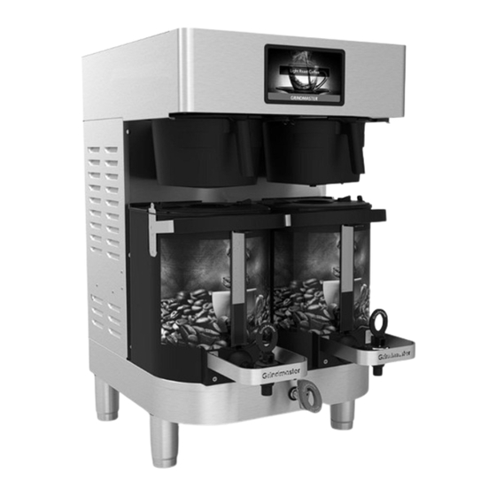
Model shown:
PBC-2A2
1118 Form # BW-345-01
Part # 390-00124
Advertisement
Table of Contents

Subscribe to Our Youtube Channel
Related Manuals for Grindmaster Cecilware PrecisionBrew PBC-2A2

Summary of Contents for Grindmaster Cecilware PrecisionBrew PBC-2A2
-
Page 1: Table Of Contents
Operator Manual Original language PrecisionBrew Coffee Brewers ™ Model shown: PBC-2A2 Table of Contents Safety Information....2 Programming ......11 Additional Notices ....5 Cleaning.........13 Installation.......7 Maintenance ......14 Start up ........8 Special Control Functions ..15 Operation ........9 Troubleshooting Guide..16 Control Features....10 Thermistor Chart ....23 Adjustments ......10 Parts Diagram and List..23 Air-Heated Shuttle Lighting .11... -
Page 2: Safety Information
Safety Information This is the safety alert symbol. It is used to alert you to potential personal injury hazards. Obey all safety messages that follow this symbol to avoid possible injury or death. This symbol means read the operator manual for important safety information. This symbol means electrical shock hazard. - Page 3 Safety Information (continued) WARNING Dangerous voltages and hot surfaces are present inside the machine. Maintenance should only be performed by qualified service personnel. Do not place any potentially flammable materials on or near brewer or server base at any time. CAUTION For safe and proper operation, the appliance must be placed in a stable, vertical position.
- Page 4 Safety Information (continued) NOTICE Ambient temperatures must be between 4°C and 40°C. Do not use extension cord. Airborne noise emissions: Measured A-weighted noise levels of the product are 53 dB(A). This equipment must be installed in compliance with applicable Federal, State, and/or Local plumbing codes having jurisdiction.
-
Page 5: Additional Notices
Additional Notices Foreword The installation, use, and maintenance manual (hereinafter Manual) provides the user with information necessary for correct and safe use of the machine (hereinafter “machine” or “appliance”). The following must not be considered a long and exacting list of warnings, but rather a set of instructions suitable for improving machine performance in every respect and, above all, preventing injury to persons and animals and damage to property due to improper operating procedures. - Page 6 Additional Notices (cont.) The employer, workplace manager or service technician are responsible for identifying and choosing adequate and suitable personal protection equipment to be worn by operators, in compliance with regulations in force in the country of use. Manufacturer declines any liability for inaccuracies contained in the manual, if due to printing or translation errors.
-
Page 7: Installation
Installation Model Description PBC-1A2 Coffee brewer, single virtual sightglass, air heated shuttle PBC-2A2 Coffee brewer, double virtual sightglass, air heated shuttle PBC-1W2 Coffee brewer, single sightglass, warmer shuttle PBC-2W2 Coffee brewer, double sightglass, warmer shuttle PBC-1V2 Coffee brewer, single, vacuum shuttle without stand PBC-2V2 Coffee brewer, double vacuum shuttle without stand PBC-1VS2... -
Page 8: Start Up
Installation (continued) 2. Use copper or flexible water line to prevent strain. pole. Do not use low temperature plastic tubing. The 3. The brewer is supplied with a power cord for the connection to the fill valve is 3/4" BSP. specified power supply receptacle. -
Page 9: Operation
Start up (continued) the basket(s). Brew at least one batch from each d) SERVER NOT IN PLACE - place appropriate side. Check the level in the container to be sure the Server in place under brew basket until brew volume is correct. Remember that when using presence switch is activated. -
Page 10: Control Features
Adjustments WARNING: ELECTRIC SHOCK HAZARD! Dangerous electric voltages are present near adjustable components. All adjustments should be performed by qualified service personnel only. All adjustments to machine are accessible through the front display. Refer to specifics below and the Programming Routine section. -
Page 11: Air-Heated Shuttle Lighting
Air-Heated Shuttle Lighting Backlighting Lighting Color sequences: If freshness timer setting is “ON”: • Solid Green backlighting: After brewing; 30-5 minutes remaining in the freshness timer • Solid Yellow backlighting: 5 to 0 minutes remaining in the freshness timer • Solid Red backlighting: Freshness timer elapsed If freshness timer setting is “OFF”: Backlighting randomly cycles colors as long a... - Page 12 Programming (continued) Brewer Prog ramming screen le s ools ou ou ch ch o o t t t) r “ ” g H “ ” g ss C “ e “ ” s ” ti c ” n ecip elect e “...
-
Page 13: Cleaning
Cleaning 8. Wash the faucet shank with a bottle brush. CAUTION: BURN HAZARD 9. Clean the warmer and bottom of shuttle surfaces. Hot liquids and surfaces are present in this These surfaces must be clean for proper heat equipment. To avoid burns, use caution when transfer. -
Page 14: Maintenance
Maintenance To Remove the Heater WARNING: ELECTRICAL AND BURN 1. Disconnect power and remove top cover of brewer. HAZARD 2. Disconnect wire leads to heater, thermistor, level Dangerous voltages and hot surfaces are present probe, and ground wires. inside the machine. Maintenance should only be 3. -
Page 15: Special Control Functions
Special Control Functions Reset factory defaults: Select Tools / More / More / Defaults buttons on LCD display Control schematic WARNING: ELECTRICAL AND BURN HAZARD Dangerous voltages and hot surfaces are present inside the machine. Maintenance should only be performed by qualified service personnel. -
Page 16: Troubleshooting Guide
Troubleshooting Guide WARNING: To reduce the risk of electrical shock, unplug the power cord before repairing or replacing any internal components of the unit. Before any attempt to replace a component, be sure to check all electrical connections for proper contact. Only a qualified service technician should perform electrical and mechanical adjustments or repairs. - Page 17 Troubleshooting Guide (continued) WARNING: To reduce the risk of electrical shock, unplug the power cord before repairing or replacing any internal components of the unit. Before any attempt to replace a component, be sure to check all electrical connections for proper contact. Only a qualified service technician should perform electrical and mechanical adjustments or repairs.
- Page 18 Troubleshooting Guide (continued) WARNING: To reduce the risk of electrical shock, unplug the power cord before repairing or replacing any internal components of the unit. Before any attempt to replace a component, be sure to check all electrical connections for proper contact. Only a qualified service technician should perform electrical and mechanical adjustments or repairs.
- Page 19 Troubleshooting Guide (continued) WARNING: To reduce the risk of electrical shock, unplug the power cord before repairing or replacing any internal components of the unit. Before any attempt to replace a component, be sure to check all electrical connections for proper contact. Only a qualified service technician should perform electrical and mechanical adjustments or repairs.
- Page 20 Troubleshooting Guide (continued) WARNING: To reduce the risk of electrical shock, unplug the power cord before repairing or replacing any internal components of the unit. Before any attempt to replace a component, be sure to check all electrical connections for proper contact. Only a qualified service technician should perform electrical and mechanical adjustments or repairs.
- Page 21 Troubleshooting Guide (continued) WARNING: To reduce the risk of electrical shock, unplug the power cord before repairing or replacing any internal components of the unit. Before any attempt to replace a component, be sure to check all electrical connections for proper contact. Only a qualified service technician should perform electrical and mechanical adjustments or repairs.
- Page 22 Troubleshooting Guide (continued) WARNING: To reduce the risk of electrical shock, unplug the power cord before repairing or replacing any internal components of the unit. Before any attempt to replace a component, be sure to check all electrical connections for proper contact. Only a qualified service technician should perform electrical and mechanical adjustments or repairs.
-
Page 23: Thermistor Chart
Thermistor Chart Resistance chart showing the ohm value of the thermistor at the appropriate temperature. THERMISTOR CURVE FOR PART # 61128 °C °F RESISTANCE (OHMS) °C °F RESISTANCE (OHMS) 16325 1244 12697 1041 9951 7856 6246 5000 4028 3266 2663 2185 1802 1493 Parts Diagram and List Labels... - Page 24 Parts Diagram and List (continued) Brew baskets – Plastic and SS t l i , s r " 4 " 6 Grindmaster ® Coffee Brewers...
- Page 25 Parts Diagram and List (continued) 1004-001 Top level panels Coffee Brewers Grindmaster ®...
- Page 26 Parts Diagram and List (continued) 1004-002 Top level panels Grindmaster ® Coffee Brewers...
- Page 27 Parts Diagram and List (continued) 1004-003 Top level panels Coffee Brewers Grindmaster ®...
- Page 28 Parts Diagram and List (continued) 1004-004 Top level panels Grindmaster ® Coffee Brewers...
- Page 29 Parts Diagram and List (continued) 1004-005 Top level panels Coffee Brewers Grindmaster ®...
- Page 30 Parts Diagram and List (continued) 1004-006 Top level panels Grindmaster ® Coffee Brewers...
- Page 31 Parts Diagram and List (continued) 230-00143 Top chassis assy-Single Coffee Brewers Grindmaster ®...
- Page 32 Parts Diagram and List (continued) 230-00166 Display assembly Grindmaster ® Coffee Brewers...
- Page 33 Parts Diagram and List (continued) 230-00099 Dome assembly Coffee Brewers Grindmaster ®...
- Page 34 Parts Diagram and List (continued) 230-00242 3kW Tank assembly 230-00243 2.5kW Tank assembly (British only) Grindmaster ® Coffee Brewers...
- Page 35 Parts Diagram and List (continued) 230-00107 Single heated shuttle chassis assembly Coffee Brewers Grindmaster ®...
- Page 36 Parts Diagram and List (continued) 230-00244 Double heated shuttle chassis assembly Grindmaster ® Coffee Brewers...
- Page 37 Parts Diagram and List (continued) 230-00109 Single vacuum shuttle chassis Coffee Brewers Grindmaster ®...
- Page 38 Parts Diagram and List (continued) 230-00245 Double vacuum shuttle chassis Grindmaster ® Coffee Brewers...
- Page 39 Parts Diagram and List (continued) 230-00196 Power supply assembly Coffee Brewers Grindmaster ®...
- Page 40 Parts Diagram and List (continued) 230-00248 Single base assembly Grindmaster ® Coffee Brewers...
- Page 41 Parts Diagram and List (continued) 230-00249 Double base assembly Coffee Brewers Grindmaster ®...
- Page 42 Parts Diagram and List (continued) 230-00261 Single IC base assembly Grindmaster ® Coffee Brewers...
- Page 43 Parts Diagram and List (continued) 230-00262 Double IC assembly Coffee Brewers Grindmaster ®...
- Page 44 Parts Diagram and List (continued) 230-00148 Presence switch bracket Grindmaster ® Coffee Brewers...
- Page 45 Parts Diagram and List (continued) 230-00121 Single shuttle shelf with mixer 230-00122 Double shuttle shelf with mixers Coffee Brewers Grindmaster ®...
- Page 46 Parts Diagram and List (continued) 230-00149 Shuttle shelf with warmer Grindmaster ® Coffee Brewers...
- Page 47 Parts Diagram and List (continued) 230-00192 Warmer interlock switch assembly Coffee Brewers Grindmaster ®...
- Page 48 Parts Diagram and List (continued) 230-00130 Shuttle shelf - vacuum shuttle 230-00121 Double shelf - vacuum shuttle Grindmaster ® Coffee Brewers...
- Page 49 Parts Diagram and List (continued) 230-00126 Air heater assembly Coffee Brewers Grindmaster ®...
- Page 50 Parts Diagram and List (continued) 230-00123 Drain hose assembly Grindmaster ® Coffee Brewers...
- Page 51 Parts Diagram and List (continued) 2503-010 Air heated shuttle assembly Coffee Brewers Grindmaster ®...
- Page 52 Parts Diagram and List (continued) 2503-011 Warmer shuttle assembly Grindmaster ® Coffee Brewers...
- Page 53 Parts Diagram and List (continued) Vacuum shuttles with and without stand l t t l t t Coffee Brewers Grindmaster ®...
-
Page 54: Wiring Diagram
Wiring Diagram 380-00443 CE Line Voltage wiring Grindmaster ® Coffee Brewers... - Page 55 Wiring Diagram (continued) 380-00443 CE Low Voltage wiring Coffee Brewers Grindmaster ®...
- Page 56 Wiring Diagram (continued) 380-00369 Air heater controls i l - i t s i t s i i t i Grindmaster-Cecilware 4003 Collins Lane, Louisville, KY 40245 USA Phone: 502.425.4776 Toll Free: 800.695.4500 Fax: 502.425.4664 Web: gmcw.com Email: info@gmcw.com 1118 Form # BW-345-01 ©2018 Grindmaster-Cecilware Part # 390-00124 Printed in USA...
Need help?
Do you have a question about the PrecisionBrew PBC-2A2 and is the answer not in the manual?
Questions and answers