Table of Contents
Advertisement
EXIT WAND
When an EXIT WAND is in use, the automatic gate operator could be activated by a
child on a bicycle, tricycle or other metal play equipment. This product is not recom-
mended for applications exposed to children.
If you are installing this product on an AC powered gate operator, we recommend you
consult a certified electrician.
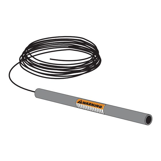
Parts Identification:
WAND with 50, 100 or 150 feet of
Double Spade
Connectors (2)
Battery Connection
Wires (2)
GTO, Inc. • 3121 Hartsfield Road • Tallahassee, Florida 32303
®
INSTALLATION MANUAL
WARNING
Direct Burial Cable
Ty-Wraps (4)
1-800-543-GATE (4283) • www.gtoinc.com
Technical Support (800) 543-1236
WARNING
!
WARNING
GATE OPENING
GA
TE OPENING SENSOR IN USE
SENSOR IN USE
The Automatic Gate Opener is activated when a
vehicle comes within range of the sensor buried
along side the driveway and could possibly be
activated by a child on a bicycle, tricycle or other
metal play equipment.
Warning Signs (2)
Wire Nuts (3)
Adjustment Board
Wire Clamp
Range
RWINSTPRO
rev-7/13/04
Advertisement
Table of Contents

Summary of Contents for GTO/PRO EXIT WAND
- Page 1 INSTALLATION MANUAL WARNING When an EXIT WAND is in use, the automatic gate operator could be activated by a child on a bicycle, tricycle or other metal play equipment. This product is not recom- mended for applications exposed to children.
-
Page 2: Table Of Contents
If a metal object is placed directly above the wand (with little motion) it may cause the wand to activate, thus opening your gate. For this reason we do not recommend the EXIT WAND in environments exposed to children Prior to installing your wand please read the manual thoroughly. There are important safety recommendations of which you should be aware. -
Page 3: Before You Start
The metal object must be in motion to disturb the MAGNETIC FIELD, thus activating the gate operator. A stationary vehicle or object will not disturb the MAGNETIC FIELD. How the EXIT WAND’s RANGE ADJUSTMENT works • The RANGE distance can be adjusted from a 3 to 12 foot* radius from the WAND. -
Page 4: Placement Of The Wand
Placement of the WAND: Driveway • The WAND comes with 50, 100 or 150 feet of cable. A typical installation will require about 5 feet of wire to come from the ground up and into the WAND: control box for connection to the power supply and 2 feet from control board. -
Page 5: Installing The Exit Wand
Determining WAND Location: Step 1: Determine the optimum location for the EXIT WAND using the information found in “Placement of the WAND” on page 2. Then dig a hole approximately 12 inches deep and 24 inches long within two (2) feet and parallel to the edge of the driveway. -
Page 6: Wiring The Wand To Gto/Pro Low Voltage Operators
Wiring the WAND to GTO/PRO Low Voltage Gate Operators: PRO-SW1000/2000, PRO-SW3000/4000 and PRO-SL1000/2000 If you are installing the WAND on an AC Powered Operator skip forward to Page 7. For installation on other brands of operators, see page 10. IMPORTANT:... -
Page 7: Connecting The Range Adjustment Control Board
Connecting the Range Adjustment Control Board: Step 9: Connect the YELLOW wire from the WAND CABLE to the YELLOW wire from the Range Adjust- ment control board using one of the WIRE NUTS provided. Step 10: Connect the BLACK wire from the Range Adjustment control board to the BLACK BATTERY CONNECTOR wire (provided), along with the SHIELD wire from the WAND CABLE (see Step 13 below). -
Page 8: Powering Up The Wand
Powering Up the WAND: Double Spade Connectors included with WAND IMPORTANT: When the WAND is RED Operator Battery Wire first powered up it must be undis- turbed for 60 seconds to perform the self test and calibrations. Before powering the WAND make sure there are no moving metal objects or moving vehicles within range of the BLACK Operator Battery Wire... -
Page 9: Wiring The Wand To Gto/Pro Ac Powered Operators
Wiring the WAND to GTO/PRO AC Powered Gate Operators: PRO-SL5000/6000, Series and PRO-SW5000/6000 Series IMPORTANT: power b TURN OFF the efore you begin to connect the WAND wires to the control board. Step 5a: Run the cable from the WAND through the WIRE CLAMP into the control box. Pull about 8 -10 inches of cable into the control box to reach the ACCESSORY TERMINAL BLOCKs on the control board. -
Page 10: Connecting The Range Adjustment Control Board
IMPORTANT: DO NOT let exposed wiring or components on the control board make contact with other ex- posed wiring or components. Illustration B Range Adjustment Control Board GTO/PRO AC SL-5100/6100 and SW-5100/6100 ADVANCED Control Board Wire Nut – SHIELD YELLOW... -
Page 11: Power Supply Connections
Power supply connection: (See Illustration A on page 7 for BASIC unit control boards and Illustration B on page 8 for ADVANCED unit control boards.) Step 12a: Connect the RED wire from the WAND CABLE to the POSITIVE (+) terminal of the 24 VDC Acces- sory Power Terminal Block on the control board. -
Page 12: Installation On Other Brand Gate Operators
For Installation on Other Brand Gate Operators ... If you are using the EXIT WAND on any other automatic gate operator brand, use the information below for wiring the system. If you do not understand the instructions below, please call GTO’s Technical Support at 1-800-543-1236. -
Page 13: Technical Specifications
TECHNICAL SPECIFICATIONS: • Power supply: 8-26 Vac/dc. • Current consumption: 1.5 mA typical. • Relay rating: Latching relay Nominal switching capacity (resistive load) 1 Amp 30 Vdc, 0.5 Amp 125 Vac Max. switching power (resistive load) 30 Watt, 62.5 V A Max. -
Page 14: Other Gto Products
Pin Lock (FM320) for GTO/PRO 2000/2200 … The Pin Lock is a substitute for the clevis pin at front mounting point of the GTO/PRO low voltage operator arms. They help prevent theft of the operator arm while allowing quick release of the operator. - Page 15 Conversion Chart Converting Metric Units to English Equivalents When You Know Multiply By To Find Symbol centimeters 0.3937 inches in. (or ") meters 3.2808 feet ft. (or ') kilograms 2.2046 pounds lb. (or #) Converting English Units to Metric Equivalents When You Know Multiply By To Find...
Need help?
Do you have a question about the EXIT WAND and is the answer not in the manual?
Questions and answers