Maxtec MAXO2+A Manual & Operating Instructions
Scuba oxygen analyzer
Hide thumbs
Also See for MAXO2+A:
- Operating instructions manual (13 pages) ,
- Instructions for use manual (11 pages) ,
- Industrial manual & operating instructions (24 pages)

Related Manuals for Maxtec MAXO2+A


Summary of Contents for Maxtec MAXO2+A
- Page 1 MAXO ® MAXO ® MAXO ® A / AE INDUSTRIAL GUIDE & OPERATING INSTRUCTIONS R 2 1 7 M 4 2 R e v . K...
-
Page 2: Classification
+ oxygen sensor in the MAXO + Analyzer to be free from defects in material and workmanship for a period of 2-years from Maxtec’s date of shipment in a MAXO + unit. Should a sensor fail prematurely, the replacement sensor is warranted for the remainder of the original sensor warranty period. - Page 3 Please feel free to write, FAX or e-mail us at the address on page ii of this manual c/o the Maxtec Marketing Department. Please visit our website www. maxtec.com for more information on our products and services.
- Page 4 Use of the MAXO near devices that generate electrical fields may cause erratic readings. If the MAXO is ever exposed to liquids (from spills or immersion) or to any other physical abuse, turn the instrument OFF and then ON. This will allow the unit to go through its self test to assure everything is operating correctly.
- Page 5 Safety Labeling The following symbols and safety labels are found on the MAXO Follow instructions for use. On/off Button Warning Calibration Button Meets ETL standards Low Battery Do not throw away. Follow local Percent guidelines for disposal. Calibration required Manufacturer REF Catalog Number Lot code/Batch code Serial Number...
-
Page 6: Table Of Contents
TABLE OF CONTENTS Classification ..............ii Warranty . -
Page 7: System Overview
1.0 SYSTEM OVERVIEW 1.1 Base Unit Description The MAXO analyzer provides unparalleled performance and reliability due to an advanced design that includes the following features and oper- ational benefits. • Extra-life oxygen sensor of approximately 1,500,000 O percent hours (2-year warranty) •... -
Page 8: Component Identification
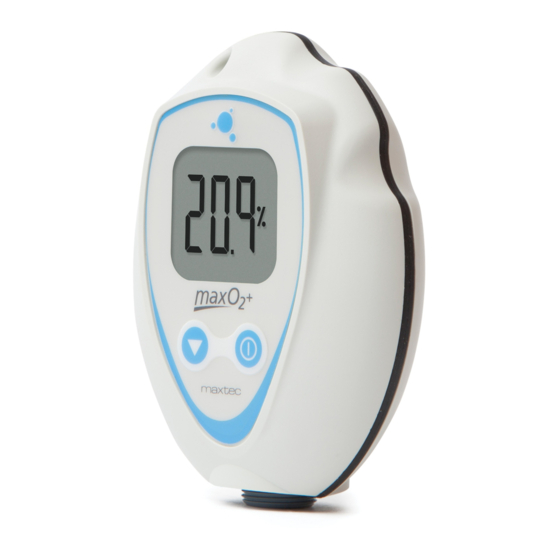
1.2 Component Identification FIGURE 1 1.3 Component Description 1. 3 1/2-Digit Display - The 3 1/2 digit liquid crystal display (LCD) provides direct readout of oxygen concentrations in the range of 0 - 105.0% (100.1% - 105.0% used for calibration determination purposes). -
Page 9: Max-250 Oxygen Sensor
(Pb), and lead acetate. Lead and lead acetate are hazardous waste constituents and should be disposed of properly, or returned to Maxtec for proper disposal or recovery. CAUTION: Do not immerse the sensor in any cleaning solution, autoclave or expose the sensor to high temperatures. -
Page 10: Calibrating The Maxo Oxygen Analyzer
® The MAXO Analyzer should be calibrated upon initial power-up. Thereafter, Maxtec ® recommends calibration on a weekly basis. To serve as a reminder, a one week timer is started with each new calibration. At the end of one week a reminder icon “... -
Page 11: Operation With Oxyknob Adapter
A simple calibration may be made with the sensor open to static Ambient air. For optimum accuracy Maxtec recommends that the Sensor be placed in a closed loop circuit where gas flow is moving across the sensor in a controlled manner. -
Page 12: Operation With Bc Adapter
2.4 Operation with Optional BC Adapter (refer to figure below) 1. Attach the included Barbed Adapter to the MAXO by threading it on to the bottom of the sensor. 2. Connect the included tubing to the barbed adapter. 3. Attach the BC adapter (sold separately) to the other end of the tube. 4. -
Page 13: Gas Sample Options
3.0 GAS SAMPLE OPTIONS W W W . M A X T E C . C O M... -
Page 14: Factors Influencing Accurate Readings
4.0 FACTORS INFLUENCING ACCURATE READINGS 4.1 Elevation Changes • Changes in elevation result in a reading error of approximately 1% of reading per 250 feet. • In general, calibration of the instrument should be performed when elevation at which the product is being used changes by more than 500 feet. 4.2 Temperature Effects The MAXO will hold calibration and read correctly within ±3% when in ther-... -
Page 15: Calibration Errors And Error Codes
E02: No sensor attached MAXO A: Open unit and disconnect and reconnect sensor. Unit should perform an auto calibration and should read 20.9%. If not, contact Maxtec Customer Service for possible sensor replacement. MAXO AE: Disconnect and reconnect external sensor. Unit should perform an auto calibration, and should read 20.9%. -
Page 16: Changing The Batteries
Maxtec Customer Service for possible sensor replacement. CAL Err hi: Sensor voltage too high Press and hold the Calibration Button for three seconds to manually force a new calibration. If unit repeats this error more than three times, con- tact Maxtec Customer Service for possible sensor replacement. -
Page 17: Changing The Oxygen Sensor
positioning the wires so they are not pinched between the two case halves. The gasket separating the halves will be captured on the back case half. Reinsert the three screws and tighten until the screws are snug. (figure 4) The device will automatically perform a calibration and begin displaying % of oxgen. -
Page 18: Maxo Ae Model
• Clean the sensor with a cloth moistened with a 65% alcohol/water solution. • Maxtec does not recommend use of spray disinfectants because they can M A N U F A C T U R E D B Y M A X T E C... -
Page 19: Specifications
65% alcohol/water solution (per manufacturer’s instructions). The parts must be thoroughly dry before they are used. Because of the variability of the cleaning processes, Maxtec cannot provide specific instructions. Therefore, we highly recommend referring to the manu- facturer’s instructions on the details of method. -
Page 20: Sensor Specifications
9.2 Sensor Specifications Type: Galvanic fuel sensor (0-100%) Life: 2-years in typical applications 10.0 MAXO SPARE PARTS AND ACCESSORIES 10.1 Included With Your Unit A Model Part Number Item AE Model R217M42 Industrial Guide and Operating Instructions RP76P06 Lanyard R207P17 Threaded Adapter with Tygon Tubing R110P10 Flow Diverter... -
Page 21: Mounting Options
10.3.2 Mounting Options (requires dovetail-R217P23) Part Number Item R103P01 M16 x 1 Maxtec Nut R205P86 Wall Mount R213P31 Swivel Mount 10.3.3 Carrying Options Part Number Item R213P02 Zipper Carrying Case with Shoulder Strap R213P56 Water Tight Carrying Case, Large (9” x 11”) R213P90-001 Water Tight Carrying Case, Small (8”...
Need help?
Do you have a question about the MAXO2+A and is the answer not in the manual?
Questions and answers