
Related Manuals for 4SQRP Hilltopper-20

Summary of Contents for 4SQRP Hilltopper-20
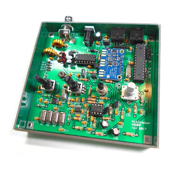
- Page 1 The ‘Hilltopper-20’ …a compact 20M CW transceiver. Offered by the 4-State QRP Group The ‘Hilltopper-20’ Transceiver K1SWL rev. 15 October 2018...
- Page 2 To avoid having to keep switching back and forth between code elements, there’s a 50 mS ‘hang’ time on key-up. The Hilltopper firmware is open-source and can be downloaded from https://4sqrp.groups.io/g/HilltopperKit See the ‘file section s’ The ‘Hilltopper-20’ Transceiver K1SWL rev. 15 October 2018...
-
Page 3: Parts List
Glass case, larger BNC jack, right-angle mount DC power jack J3, J4 Key and audio jacks, 3.5mm 3-cond. 6-pin .100” male header not supplied in kit 4-pin .100” male header not supplied in kit The ‘Hilltopper-20’ Transceiver K1SWL rev. 15 October 2018... - Page 4 Assembly sequence: You’ll find 7 grouped assembly sequences in these pages. You don’t have to follow them. Caution: There’s one component installation where the order matters. That’s diode D7, which is *under* the Si5351 board. Install it before you add the Si5351 board. It’s also The ‘Hilltopper-20’ Transceiver K1SWL rev. 15 October 2018...
-
Page 5: Before You Start
ICs not be removed from their anti-static packaging until you are ready to install them. If parts are missing in your kit, send an email to the Hiltopper kitter listed at 4SQRP.com. He will promptly provide replacements. It is helpful to acquire the necessary tools and supplies before beginning. These include: *Soldering iron –... - Page 6 3 or 4 components, then solder each and clip off the excess lead length. Locations are highlighted below. • • • • • • • • • • • • • • • µ µ µ µ µ The ‘Hilltopper-20’ Transceiver K1SWL rev. 15 October 2018 µ...
- Page 7 3 or 4 components, then solder each and clip off the excess lead length. Locations are highlighted below. • • • • • • • • • µ µ µ µ The ‘Hilltopper-20’ Transceiver K1SWL rev. 15 October 2018...
- Page 8 Reheat the connection if needed to align µ the connector properly. Once the alignment is OK, solder the remaining leads on the connector. µ µ µ µ µ The ‘Hilltopper-20’ Transceiver K1SWL rev. 15 October 2018 µ µ µ...
- Page 9 IC pins gently inward to mate with the socket. The best approach is push the IC down on a hard surface to bend one 14-pin row at a time evenly. Once The ‘Hilltopper-20’ Transceiver K1SWL rev. 15 October 2018...
- Page 10 • • • • • • • • • • • • • µ • µ • Install J3 and J4. • Install Install U6 (78L05). Observe proper orientation on the board. The ‘Hilltopper-20’ Transceiver K1SWL rev. 15 October 2018...
- Page 11 • Install resistors R13 and R23 (4.7 ohm yellow-violet-gold-gold) • Install resistor R8 (22K ohm, red-red-orange-gold) • Install electrolytic caps C29 and C30. Observe installation polarity. The longer wire lead corresponds to the positive (+) side of the cap. The ‘Hilltopper-20’ Transceiver K1SWL rev. 15 October 2018...
- Page 12 • Install capacitor C18 - .033 uF (marked ‘333’) • Install capacitor C16 - 47 pF (marked ‘470’ or ’47J’) • Install capacitor C17 - 68 pF (marked ‘680’ or ’68J’) µ The ‘Hilltopper-20’ Transceiver K1SWL rev. 15 October 2018 µ...
- Page 13 Install all components highlighted below. A detailed assembly sequence follows. • Install capacitors C1, C3, C8 and C12 - 47 pF (marked ‘470’ or ‘47J’). • Install capacitor C6 - 10 pF (marked ‘100’or ;10J’). The ‘Hilltopper-20’ Transceiver K1SWL rev. 15 October 2018...
- Page 14 • Install diodes D2 through D5 - 1N4148. Be to match the banded end of each diode to the banded marking on the circuit board component outline. Note: D3 and D4 bands to the right, D2 and D5 bands to the left. The ‘Hilltopper-20’ Transceiver K1SWL rev. 15 October 2018...
- Page 15 •Wind 8 turns of #21 (thicker) wire on toroid L5 (FT37-43 gray toroid). Trim excess lead length to 3/8” (1 cm). Using a small knife, gently scrape the insulation from the protruding leads. (The insulation will not melt when you apply a soldering iron.) The ‘Hilltopper-20’ Transceiver K1SWL rev. 15 October 2018...
- Page 16 68 pF (marked ‘680’ or ’68J’). • Install BNC bulkhead jack J1. Use sandpaper or file to roughen plating to ensure a good solder joint. (This completes assembly of the main circuit board.) The ‘Hilltopper-20’ Transceiver K1SWL rev. 15 October 2018...
-
Page 17: Final Assembly
Holding the top cover, turn unit over and complete soldering the controls. 10) Perform the Alignment and BFO Pitch Adjustment processes as described in the next section. 11) Replace the top cover with spacers. The ‘Hilltopper-20’ Transceiver K1SWL rev. 15 October 2018... - Page 18 Space the knobs slightly above the panel to prevent ‘rubbing’. The tuning knob must be just high enough to allow the detent switch on the rotary encoder to function. (This completes assembly of the kit.) The ‘Hilltopper-20’ Transceiver K1SWL rev. 15 October 2018...
- Page 19 Power up the hilltopper (it starts up on 14060.0.) Set your big rig to 14060.0 and send a string of dots (low power, please!). Adjust C53 so that the received pitch in the Hilltopper matches your sidetone pitch. * * * The ‘Hilltopper-20’ Transceiver K1SWL rev. 15 October 2018...
-
Page 20: Operation
Pressing the TUNING switch down while applying DC power to the Hilltopper yields a startup frequency of 14030.0 kHz.. This saves a lot of knob-twisting if you usually work the low end of 20M The ‘Hilltopper-20’ Transceiver K1SWL rev. 15 October 2018... -
Page 21: Receiver Schematic
Receiver Schematic: The ‘Hilltopper-20’ Transceiver K1SWL rev. 15 October 2018... - Page 22 The ‘Hilltopper-20’ Transceiver K1SWL rev. 15 October 2018...
- Page 23 Transmitter/Controller Schematic: The ‘Hilltopper-20’ Transceiver K1SWL rev. 15 October 2018...
- Page 24 He also graciously provided open-source firmware…… which I proceeded to mangle for this project. Thanks also to David Cripe- NMOS- who played an invaluable role with enclosure layout, technical liason with 4SQRP, and provided advice with component selection. Dave Benson, K1SWL 14Nov. 2017 The ‘Hilltopper-20’ Transceiver K1SWL rev.
Need help?
Do you have a question about the Hilltopper-20 and is the answer not in the manual?
Questions and answers