Advertisement
Table of Contents
- 1 Table of Contents
- 2 Precautions for Use
- 3 For Proper Use
- 4 Main Body and Structure
- 5 Specifications
- 6 External Output
- 7 Outside Dimensions
- 8 Service Life
- 9 External Connection
- 10 Instructions for Installation and Piping Work
- 11 Functions
- 12 Instructions for the Beginning of Use
- 13 Instructions for Inspection
- 14 Remote Indicator (Optional)
- 15 Characteristic Data (Reference)
- 16 Troubleshooting
- Download this manual
Reliability Creativity Service
For Gas Management & Control
Built-in battery Type: TBX30, TBX100, TBX100F, TBX150F
External Power Source Type: TBX30D, TBX100D, TBX100FD, TBX150FD
Thank you for purchasing this product.
Please read through this instruction manual carefully and use the product properly.
The warranty is on the back cover. Please review the content and keep it for future
reference.
Sensors, Systems & Service
Instruction Manual
Turbine Gas Meter
TBX150F
(Built-in battery
type)
Warranty included
TBX30D
(External power
source type)
Aichi tokei denki co., ltd.
Advertisement
Table of Contents

Related Manuals for Aichi Tokei Denki TBX30

Summary of Contents for Aichi Tokei Denki TBX30
- Page 1 Warranty included Reliability Creativity Service Instruction Manual For Gas Management & Control Turbine Gas Meter Built-in battery Type: TBX30, TBX100, TBX100F, TBX150F External Power Source Type: TBX30D, TBX100D, TBX100FD, TBX150FD TBX30D (External power source type) TBX150F (Built-in battery type) Thank you for purchasing this product.
-
Page 2: Table Of Contents
Contents 1 Indications used in this instruction manual 10 Instructions for installation and piping work ............1-2P ............12-13P 2 Precautions for use ......2-3P 11 Functions ........14-18P 3 For proper use ........3-4P 12 Instructions for the beginning of use .. 19P 4 Main body and structure .... -
Page 3: Precautions For Use
Precautions for use Caution Do not install the product at a dangerous place. Do not use the product for applications to which a high level of safety is required, such as nuclear power, railway, aviation, vehicle, and amusement applications. The electric circuits in this turbine meter do not have an anti-explosion structure. Do Not Do not use this product for the measurement of corrosive gases or the gases listed below. -
Page 4: For Proper Use
Disposal after use Never dispose of the meter through a general waste processing route because a lithium battery is embedded inside (applicable for the Built-in battery type). Never throw the meter into a fire. It may ignite or explode. For proper use Be sure that the gas the customer is going to use agrees with the specifications shown on the nameplate. - Page 5 Do not install the meter at a place where oil mist or powder of dust is wafting. 1. Use the meter in a condition in which the generation of oil mist due to reliquefaction can be avoided. Oil mist that adheres to inside the flow rate meter may cause errors in flow rate measurement, hindering accurate measurement.
-
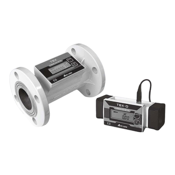
Page 6: Main Body And Structure
Main body and structure Checking the content of the package Check the following items when this product is delivered. Check the model name to make sure it is the product you have ordered. Check the appearance to make sure the product is not broken. Verify the accessories with the specifications. - Page 7 Not indicated Built-in battery type External power source type Left inlet (left to right) Right inlet (right to left) Bottom inlet (bottom to top) TBX100F (D) only Top inlet (top to bottom) 32A (Rc 1 TBX30 (D) only 40A (Rc 1...
-
Page 8: Specifications
Specifications Model TBX30(D) TBX100(D) TBX100F(D) TBX150F(D) Flow rate range (m 4 – 30 10 – 100 10 – 100 12.5 – 150 Maximum allowable working pressure (kPa) Withstanding pressure (kPa) ± 1% FS Accuracy LCD display: LCD display: 8 digits Integrated Minimum readout value: 0.01 m... -
Page 9: External Output
The maximum frequency with the standard specifications. The maximum frequency varies with the pulse output unit that has been set. Note that the maximum frequency will be approximately 8 Hz when the pulse output unit of TBX30 (D) is set to 1 L/P. -
Page 10: Outside Dimensions
Outside dimensions The direction of the indicator of TBX100F (D) can be freely adjusted to accommodate to the inflow direction of the gas. In addition, the indicator can be detached to be used as a remote External dimensions display. Model Service life Standard Name... -
Page 11: External Connection
External connection Built-in battery type Use the dedicated external connection cable (optional) to extract the external pulse output signals (open drain). For the connection between the meter main body and the indicator, connect the signal wires of the indicator to the terminal box of the external connection cable (4 wires, 2 m) as follows. - Page 12 Wire color Description Power supply 12 to 24 VDC Black Power GND Unit pulse (+) White Unit pulse (-) Blue External connection cable (5 m) High-density pulse (+) Yellow High-density pulse (-) Green Terminal box (optional) The terminal box is used when the external connection cable and the indicator are connected indirectly.
-
Page 13: Instructions For Installation And Piping Work
On that occasion, use caution not to make a short circuit. The power source used should be an isolation type having a short-circuit protection function. (1) In case of TBX30 (D) On installation Secure the connection unit first, and then screw pipes with tapered external threading into both ends of the meter. - Page 14 (2) In case of TBX100F (D) The direction of the display of this product can be freely adjusted to accommodate to the inlet direction of the gas. In addition, the display can be detached to be used as a remote display. Remove the "bolt with a hexagon hole"...
-
Page 15: Functions
(*1) Applicable only for the Built-in battery type TBX100 (D) Model Category TBX30 (D) TBX150F (D) Name TBX100F (D) While an integrated flow rate value is displayed: Pressing the switch (for less than one second) will display an instantaneous flow rate value. - Page 16 Constant display mode During normal operation (while a flow rate value is displayed), pressing and holding the “FLOW RATE” switch and the “START” switch together for four seconds or longer will change the display to this mode. You can select various setting items in sequence by pressing the “FLOW RATE” switch. Pressing the “FLOW RATE”...
- Page 17 Pulse output unit setting Select the No.4 mode. Pressing and holding the “FLOW RATE” switch for two seconds (i.e. start of setting) will make the setting value for pulse output unit blinking (0.5 seconds interval). You can change the setting value for pulse output unit in the range from 1 to 10,000 L/P by pressing the “FLOW RATE”...
- Page 18 Pulse output width setting Select the No.5 mode. Pressing and holding the “FLOW RATE” switch for two seconds (i.e. start of setting) will make the setting value for output pulse width blinking (0.5 seconds interval). You can change the setting value for pulse output width between 40 and 120 in order by pressing the “FLOW RATE”...
- Page 19 (applicable only for the Built-in battery type) Inventory mode The product has the inventory mode for reducing the power consumption while it is in stock. In the inventory mode, the LCD display becomes "--------" and integration and pulse output will not be carried out even when air flows. The following figure shows how to operate the meter to change to and return from the inventory mode.
-
Page 20: Instructions For The Beginning Of Use
12 Instructions for the beginning of use Open the inflow valve (upstream from the meter) gradually. Open the outflow valve (downstream from the meter) gradually. Check that the pilot is blinking. Change the indicator display of the meter to an instantaneous flow rate value, and then adjust the valve so that the flow rate value is in the specified range. -
Page 21: Remote Indicator (Optional)
14 Remote indicator (optional) Types of remote indicators Model Functions Power source Instantaneous flow rate display, integrated flow rate ZC09-96 Embedded battery display, pulse output Instantaneous flow rate display, integrated flow rate 85 to 264 VAC ZX-564 display, pulse output, analog output, alarm output (free power source) Selectable from 100 VAC, RE101... -
Page 22: Characteristic Data (Reference)
15 Characteristic data (reference) Turbine meter TBX30 (D) general performance diagram (low-pressure air) Instrumental Pressure loss error Instantaneous flow rate [m Turbine meter TBX100 (D), TBX100F (D) general performance diagram (low-pressure air) Instrumental Pressure loss error Instantaneous flow rate [m... -
Page 23: Troubleshooting
16 Troubleshooting In the event you encounter a trouble that could be caused by a failure of the meter, refer to the following table first. If the symptom is not listed in this table or the measures in this table does not improve the situation, contact your nearest branch office or sales office. - Page 24 Refer to the following for the provisions of this warranty. Provisions for free-of-charge replacement Aichi Tokei Denki will replace the product at no charge in the event that it goes out of order within one year under normal use conditions in accordance with the directions in the instruction manual.
Need help?
Do you have a question about the TBX30 and is the answer not in the manual?
Questions and answers