
Summary of Contents for Accu-Turn 1400
- Page 1 OPERATOR’S MANUAL MANUEL DE L’OPÉRATEUR MANUAL PARA EL OPERADOR Digital Wheel Balancer - ZEEWB604A Machine à équilibrer Equilibradora...
- Page 2 LIMITES D’APPLICATION DE LA GARANTIE ET VENCIMIENTO DE LA GARANTÍA Y LIMITATIONS DE LA GARANTIE LIMITACIONES DE RESPONSABILIDAD Bien que les auteurs aient accordé la plus grande A pesar de que los autores han prestado la máxima attention à la rédaction du présent manuel, aucun atención al redactar este manual, se señala que el élément figurant dans ce dernier: contenido del mismo:...
- Page 3 LIMITED WARRANTY Accu Industries, Inc. (“Seller”) provides a one year limited warranty on parts and labor on all goods manufactured by it, including this product. The sole and exclusive warranty which Seller makes with respect to this product and all parts and accessories thereto which are sold by Seller is a warranty limited to defects in material or workmanship for a period of one year from the date of original purchase by Buyer from Seller.
- Page 4 GARANTIE LIMITEE GARANTÍA LIMITADA Accu Industries, Inc. (“Vendedor”) prevé una garantía La société Accu Industries, Inc. (le “Vendeur”) fournit limitada de un año en lo que atañe a piezas y mano de obra une garantie limitée à un an sur les pièces et la main-d’œuvre sur suministradas, incluyendo este producto.
-
Page 5: Table Of Contents
Table of Contents Safety............. 8 Typography..........8 Specifications........10 Conditions..........10 Introduction.......... 12 Accessories........... 14 Layout..........16 The display..........18 4.1.1 Audible System signals......18 The Control Panel........20 Operation..........22 Mounting the wheel. - Page 6 Table des matières Índice Sécurité ..........9 1 Seguridad............9 Typographie..........9 1.1 Tipografía............9 Spécifications........11 Especificaciones........11 Conditions..........11 Condiciones..........11 Introduction.......... 13 Introducción......... 13 Accessoires........... 15 Accesorios..........15 Disposition.
-
Page 7: Safety
Safety 1 Safety. All Safety Precautions relevant to the unit are described in the Safety Booklet, refer to Figure 1-1. The Safety Precautions must be fully understood by every operator. We suggest you keep a copy of the Safety Booklet near the unit, within reach of the operator. -
Page 8: Sécurité
Sécurité Seguridad 1 Sécurité 1 Seguridad. Toutes les mesures de sécurité se rapportant à l’unité En el Folleto de Seguridad se describen todas las sont décrites dans le Livret de Sécurité, se reporter à Precauciones de Seguridad relativas a la unidad, Figure 1-1. -
Page 9: Specifications
Specifications Specifications. Power: Power 115V~, 1Ph, 50/60Hz, 3.8A Motor power 0,12 Electrical consumption Fuses 2 x T5 Protection class IP54 Measurements: Cycle time (wheel D.14”) >6 Speed of rotation range 130-180 rpm Offset 0-250 Increments: inches (<10”) 0.5 (.25) ” Wheel dimensions: Max. -
Page 10: Spécifications
Especificaciones Spécifications Spécifications. Especificaciones. Alimentation Potencia eléctrica: Alimentation Suministro Corriente eléctr. 115V~, 1Ph, 50/60Hz, 3.8A 115V~, 1Ph, 50/60Hz, 3.8A Puissance moteur Indice motor 0,12 0,12 Consommation électrique Consumo eléctrico Fusibles Fusibles red eléctrica 2 x T5 2 x T5 Classe de protection Tipo de Protección IP54 IP54... -
Page 11: Introduction
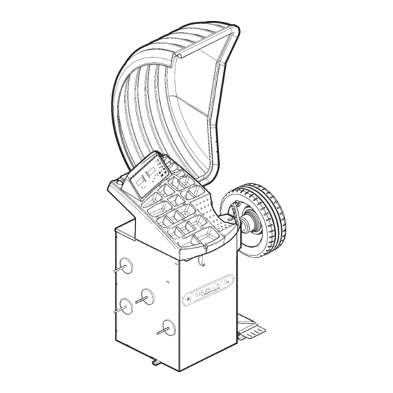
Introduction Introduction. This wheel balancer combines advanced, high-perfor- mance technology, durability and reliability with very simple, user-friendly operation. The low rotation speed of the wheel and the large wheel protection ensures that this balancers is very safe. It features an easy-to-use display and control panel, ensuring fast and intuitive operation. -
Page 12: Introduction
Introducción Introduction Introduction. Introducción. Cette équilibreuse vous offre une technologie avan- Esta equilibradora de ruedas combina una tecnología cée de haute performance, solidité et fiabilité et son avanzada y de alto rendimiento, robustez y confianza, opération est très simple et conviviale. con un funcionamiento sencillo y fácil de manejar. -
Page 13: Accessories
Introduction Accessories. Refer to Figure 3.1-1. The standard equipment accessories are: Quick-Release Hub Nut 10201462 Spacer ring 10017671 Universal drum 10017672 Universal drum cushion 10018618 Large cone 10025539 Medium cone 10025518 Small cone 10025517 Stub shaft 10025516 Shaft tightening stud 14025821 User Calibration weight 50025415... -
Page 14: Accessoires
Introducción Introduction Accessoires. Accesorios. Se reporter à la Figure 3.1-1. Consultar lao Figura 3.1-1. Les accessoires standard sont: Los accesorios normales son: Manivelle de serrage rapide 10201462 Tuerca rapida 10201462 Disque de distance 10017671 Espaciador 10017671 Coupelle plastique 10017672 Tambor Universal 10017672 Joint protection de la coupelle 10018618 Amortiguador tambor universal 10018618... -
Page 15: Layout
Layout Layout. Refer to Figure 4-1. Functional description of the unit: Display Refer to Chapter 4.1. Control panel Refer to Chapter 4.2. Gauge arm The gauge arm is a tool for measuring the rim. Flange Stub shaft Brake pedal Weight compartments Storage areas for cones or accessories Tilting frame and hood Storage area for Width Caliper... -
Page 16: Disposition
Disposición Description Description. Disposición. Se reporter à la Figure 4-1. Consultar Figura 4-1. Description fonctionnelle de la machine : Descripción funcional de la unidad: 1. Affichage Pantalla Se reporter au Chapitre 4.1. Consultar Capítulo 4.1. 2. Clavier Panel entrada datos Se reporter au Chapitre 4.2. -
Page 17: The Display
Layout The display. Refer to Figure 4.1-1. Note: Positions related to the internal (left) plane of the wheel are labeled with a number followed by “a”, while for external (right) plane positions the number is followed by “b” (e.g.: 1a, 1b). Weight Application Position (WAP) indica- tor. -
Page 18: L'affichage
Disposición Description L’affichage. La Pantalla. Se reporter à la Figure 4.1-1. Ver Figura 4.1-1. Remarque: Les positions se rapportant au plan Nota: Las posiciones relativas al plano izquier- gauche sur la roue sont numérotées avec do de la rueda están numeradas con un un «a», les positions du plan droit avec «a»... -
Page 19: The Control Panel
Layout The Control Panel. Refer to Figure 4.2-1. Rim Offset Key. To increase the balancers offset (distance between the left side of the rim and the balancer cabinet) shown on the display. Hold down this key to rapidly increase the value. Rim Offset and Calibration Key. -
Page 20: Le Clavier
Disposición Description Le Clavier. El panel de entrada. Se reporter à la Figure 4.2-1. Consultar la Figura 4.2-1. 1. Touche Déport Jante. 1. Tecla Distancia Llanta. Pour augmenter la valeur, visualisée sur l’afficheur, de Sirve para incrementar el valor que aparece en la pan- la distance entre le bord interne de la jante et l’armoire. -
Page 21: Operation
Operations Operation. This chapter describes how to operate the computer balancer in order to balance a wheel. The standard balancing runs will be described first. In chapter 5.4 and higher special modes and functions will be described. Be sure to be familiar with: possible dangers, refer to chapter 1 the balancer, refer to chapter 4. -
Page 22: Utilisation
Funcionamiento Description Utilisation. Funcionamiento. Ce chapitre décrit l’utilisation de la machine pour équi- En este capítulo se describe cómo trabajar con la uni- librer une roue. dad para equilibrar las ruedas. Les étapes d’équilibrage standard sont décrites en Primero se describe el funcionamiento normal de equi- premier. - Page 23 Operations Press the protective rubber ring to the universal drum to prevent damage to painted or non-steel rims. Refer to Figure 5.1-2. From top to bottom the following cone clamping systems are shown: A. Back Cone Mounting with Universal Drum. The cone centers on the wheel from inside.
- Page 24 Funcionamiento Description Installer la coupelle de protection pour éviter d’endom- sión para evitar dañar las llantas pintadas o que no mager les jantes peintes ou qui ne sont pas en acier. sean de acero. Se reporter à la Figure 5.1-2. Les systèmes de blo- cage par cône suivant sont indiqués, de haut en bas : Ver Figura 5.1-2.
- Page 25 Operations Adapter Mounting (optional). Refer to Figure 5.1-3. From top to bottom: (A) Universal Wheel Adapter #14026608 Remove the threaded shaft then fit the adapter. For 3 holes: fit the 3 stud bolts in the holes stamped with the number 3. For 4 holes: fit the 4 stud bolts in the holes stamped with the number 4.
- Page 26 Funcionamiento Description Installation adaptateurs (sur demande). Ver Figura 5.1-3. En la misma se indica, de arriba a Se reporter à la Figure 5.1-3. De haut en bas on peut abajo: voir: (A) Adaptador Rueda Universal #4026608 (A) Adaptateur universel #4026608 Montar el adaptador después de haber desmontado Installer l’adaptateur après avoir démonté...
-
Page 27: Wheel Mounting Errors
Operations 5.1.1 Wheel Mounting Errors. Refer to Figure 5.1.1-1. Regardless of the mounting method used, the wheel must be centered before balancing. The wheel must be clean and free of debris, espe- cially where it mates with the cone or adapter and the balancer flange. -
Page 28: Erreurs De Montage De Roue
Funcionamiento Description 5.1.1 Erreurs de montage de roue. 5.1.1 Errores en el Montaje de la Rue- Se reporter à la Figure 5.1.1-1. Indépendamment de la méthode utilisée, la roue doit Ver Figura 5.1.1-1. être centrée avant l’équilibrage. Independientemente de la forma de montaje, la rue- da debe ser centrada antes de equilibrarla. -
Page 29: Removal Of The Wheel
Operations 5.1.3 Removal of the wheel. • Carefully slacken the quick release wing nut or the mounting studs. • Do not drag the wheel on the balancers threaded shaft, but lift the wheel when removing it. • Check the thread for damage and clean if neces- sary. -
Page 30: Enlever La Roue
Funcionamiento Description 5.1.3 Enlever la roue. 5.1.3 Desmontar la rueda. • Desserrez soigneusement la manivelle de serrage • Desapriete con cuidado la tuerca fácil del cubo de rapide ou les goujons d’installation. la rueda o los tacos de montaje. • Ne faites pas glisser la jante sur les filets mais sou- •... -
Page 31: Shutting Down
Operations - wait 20 seconds - switch the balancer on again. • Carefully repeat the commands with the manual at hand. • Call Accu Service immediately if the unit does not operate correctly: WARNING: DO NOT ATTEMPT TO USE THE BAL- ANCER IF START-UP SELF TEST IS NOT SUC- CESSFUL. -
Page 32: Arrêt
Funcionamiento Description - attendre 20 secondes espere 20 segundos - remettre la machine sous tension. vuelva a encender la unidad. • Répéter soigneusement les instructions avec le • Repita cuidadosamente los comandos con el ma- manuel à portée de main. nual a mano. -
Page 33: Balancing Procedure
Operations Balancing procedure. Select the balancing mode desired by repeatidly press- ing the “ALU” button until the desired positions are illu- minated. NORMAL Used for steel rims. ALU-modes Used for alloy rims or where one or more stick-on weights are to be used. The stick-on weight(s) will be applied by hand. -
Page 34: Procédure D'équilibrage
Funcionamiento Description Procédure d’équilibrage. Procedimiento de equilibra- La machine a toujours un type de mode d’équilibrage sélectionné à l’affichage. La unidad siempre tiene un tipo de rueda selecciona- Sélectionnez la touche appropriée (reportez-vous à la do. Véalo en la pantalla. Figure 5.3-1) pour faire dérouler les différents modes Seleccione la tecla apropiada (ver Figura 5.3-1) para d’équilibrage. -
Page 35: Balancing A Wheel Type
Operations Data entry. • Obtain the rim data as described above. • On the control panel, select the required dimen- sion to edit (diameter, offset or width). The value entered last is shown. 5.3.2.0-1 • To edit the value, select the appropriate keys (refer to Chapter 4.2). -
Page 36: Équilibrage D'une Roue
Funcionamiento Description ment la valeur de déport. de la barra del brazo, luego introducir el valor en el Remarque: La longueur de la jauge peut être in- display utilizando las teclas adecuadas suffisante pour les roues de motos. Nota: El brazo de medida tiene una cierta lon- Utiliser une rallonge moto sur la jauge gitud que puede que no sea suficiente et sélectionner la procédure pour... -
Page 37: Motorcycle Dynamic Balancing Mode
Operations Note : To return to Normal mode from any ALU pro- gramme, press “STOP”. Note: In Alu 4 or Alu 5 mode, the right side (out- side plane) weight is to be placed on a verti- cal plane equal to where the wheel meets the balancers flange If you can not place the weight on this plane you will need to increase or reduce the weight amount the balancer is... -
Page 38: Equilibrage Roue Mode Dynamique Moto
Funcionamiento Description Remarque : Pour restaurer le mode Normal à par- Nota: Para volver al modo Normal desde un tir de n’importe quel programme ALU, ap- programa ALU cualquiera, pulse “STOP”. puyez “STOP”. Nota: Para ALU4 y ALU5 el plano derecho es igual Remarque: Pour ALU4 et ALU5 le plan droit de la a la superficie frontal de la pestaña. -
Page 39: Pax Wheel Balancing Mode
Operations 5.3.2.7 PAX wheel balancing mode. PAX SYSTEM wheels can be balanced with this function (see Figure 5.3.2.7-1). When the PAX function is on, the display is set for dimensions to be entered in mm as required by this type of wheel. •... -
Page 40: Mode Équilibrage Roues Pax
Funcionamiento Description 5.3.2.7 Mode Équilibrage roues PAX. 5.3.2.7 Modo Equilibrado ruedas PAX. Cette fonction (Figure. 5.3.2.7-1) permet d’équilibrer les Con esta función (ver Figura 5.3.2.7-1), es posible equili- roues type PAX SYSTEM. Quand la fonction PAX est brar las ruedas tipo PAX SYSTEM. Al seleccionar la activée, l’afficheur est prêt pour entrer les dimensions función PAX, la pantalla estará... -
Page 41: Spinning The Wheel
Operations “S - 2” will appear on the right display. Rotate in the opposite direction until you find the radial where the above mentioned index appears. Note: The field where “S – 2” appears on the dis- play is wider than radial width, therefore make sure the radial is positioned exactly at 12 o’clock before pressing “F”... -
Page 42: Lancement De La Roue
Funcionamiento Description • • Déplacez le rayon le plus proche de la partie supérieure Coloque el radio más cercano a la parte superior en la à la position à 12 heures. posición de las 12 horas. • • Appuyez la touche “F”. Pulse la tecla “F”. -
Page 43: Weight Application
Operations 5.3.4 Weight application. The following weight types and application methods are available: clip-on weights. Applied with a weight hammer. stick-on weights. Always apply by hand. Note: Weights must always be applied exactly perpendicular to the shaft (12 o’clock po- sition). -
Page 44: Pose Des Masses
Funcionamiento Description 5.3.4 Pose des masses. 5.3.4 Colocación del peso. Les types de masses et méthodes de pose suivantes Los siguientes tipos de peso y colocación están dis- sont disponibles: ponibles: masses agraffées: pesos de sujeción. Poser toujours manuellement. Colocar siempre a mano. masses adhésives: pesos adhesivos. -
Page 45: Check Spin
Operations 5.3.5 Check spin. It is good practice to perform a check spin after apply- ing the weights. • Spin the wheel. If the wheel has been balanced properly, “000” will be displayed for both planes. No WAP indicator will be lit. To check for any minor residue imbalance remaining. -
Page 46: Lancement De Vérification
Funcionamiento Description 5.3.5 Lancement de vérification. 5.3.5 Comprobar giro. Après la pose des masses, il convient de faire un lan- Es una buena practica realizar una comprobación del cement de vérification. giro después de aplicar los pesos. • Faites tourner la roue. •... -
Page 47: Special Modes
Operations Special modes. Selecting the “F” key allows the operator to use: Minimization mode, Weight units toggle mode, “oz”, Dimensional units toggle mode, “mm”, 5.4.1 Minimization mode. Select this mode if a wheel requires a weight of 3 oz. (80 grams) or more in a plane in order to be balanced. •... -
Page 48: Modes Spéciaux
Funcionamiento Description Modes spéciaux. Modos especiales. En appuyant la touche «F» ceci permet à l’opérateur Al seleccionar la tecla “F” permite que el operador se de faire dérouler les modes suivants: desplace por los siguiente modos: Mode Minimisation Modo Minimización, Mode commutation unité... -
Page 49: Weight Unit Toggle Mode
Operations Step 6: Minimization completed (Figure 5.4.2-7): • Exit Minimization Mode. Minimization to be continued (Figure 5.4.2-8): • Rotate the wheel until “888” is displayed. • Double mark the tire at the 12 o’clock position. • Remove the wheel from the unit. •... -
Page 50: Changement Des Unités De Poids
Funcionamiento Description Etape 6: Paso 6: Minimisation terminée(Figure 5.2.4-7): Minimización completada (Figura 5.4.2-7): • Sortir du Mode Minimisation. • Salir Modo de Minimización. Minimisation doit être continuée (Figure 5.2.4-8): Continuar Minimización (Figura 5.4.2-8): • Tourner la roue jusqu’à l’affichage de “888”. •... -
Page 51: Counter Functions
Operations 5.4.4 Counter Functions This section covers the use of counters, impor- tant for analysing the history of unit processes. The machine saves a large amount of data accumu- lated from the functions previously performed. Even after a short period of work, thanks to this function, you can poll the machine and obtain data useful for statistical purposes regarding work done in the work- shop, or for machine maintenance. -
Page 52: Compteurs De Contrôle
Funcionamiento Description 5.4.4 Compteurs de contrôle 5.4.4 Contadores de Control Ce chapitre traite de l’usage de compteurs, signi- En este capítulo se describe cómo usar los conta- ficatifs pour analyser l’historique des processus dores, que sirven para analizar los datos de los de l’unité. -
Page 53: Multiple Operators Selection
Operations 5.4.5 Multiple Operators Selection This chapter describes how the machine can be used alternatively by more then one Operator. The machine has a memory for saving the wheel data set by one or more operators, for several types of wheels. -
Page 54: Sélection Multi-Opérateur
Funcionamiento Description 5.4.5 Sélection Multi-Opérateur 5.4.5 Selección Multi-Operador Cette rubrique traite de la possibilité d’utiliser la En este capítulo se describe cómo varios opera- machine par plusieurs opérateurs tour à tour. dores pueden utilizar la máquina de manera alter- La machine est équipée d’une mémoire pour emma- nada. -
Page 55: Maintenance
Maintenance Maintenance. The Accu 1420 is designed for long service. At Start Up the operator must check if all indicators and displays light up. If the operator shuts down correctly (Chapter 5.2.3) at the end of his/her shift, no additional maintenance is required. -
Page 56: Maintenance
Mantenimiento Maintenance Maintenance. Mantenimiento. Cette machine est conçue pour vous donner un ser- Esta unidad está diseñada para durar mucho tiempo. vice de longue durée. Durante el modo de arranque el operador deberá com- Dans le mode de démarrage, l’opérateur doit vérifier probar si todos los indicadores y pantallas están en- que tous les indicateurs et affichages s’allument. -
Page 57: Adapter Imbalance Compensation
Maintenance Do not enter any tyre data. • Press “F” button. Display on the right will show 1. • Lower the hood to cycle the balancer shaft with nothing on it. After the measuring run the display will show 2. •... -
Page 58: Compensation Du Adapteur
Mantenimiento Maintenance USR” clignotant et ensuite “dis NNN”. mensaje “dis NNN”. N’entrer aucun paramètre roue. No introduzca ningún dato de la rueda. • Presser le bouton “F”. • Pulse la tecla “F”. L’afficheur de droite montrera 1. La pantalla de la derecha visualizará 1. Effectuer un lancement, après la mesure, l’afficheur Efectuar un giro, tras la medición la pantalla de giro de lancement montrera 2. -
Page 59: Trouble Shooting
Trouble shooting Trouble shooting. If a problem with the wheel balancer appears, proceed in the following order to solve the problem: 1. Rethink the last steps taken. Did you work according to the manual? Did the balancer work as described and expected? 2. -
Page 60: Dépannage
Resolución de problemas Dépannage Dépannage. Resolución de proble- mas. En cas de problème avec l’équilibreuse, procéder comme suit pour résoudre le problème: Si ocurre algún problema en la equilibradora, proceda en el siguiente orden para resolverlo: 1. Se remémorer les dernières actions effectuées. Le travail a-t-il été... - Page 61 Trouble shooting Wheel does not spin automatically. 1. Lowering the switch guard does not activate a wheel spin. • Check if the switch is mechanically activated by lowering the guard. 2. Electrical malfunction. • Call Accu Service. Gauge arm input differs from rim dimension stated on rim or tire.
- Page 62 Resolución de problemas Dépannage Les résultats d’équilibrage sont contradictoires. técnico. 1. Mauvais fonctionnement du switch du capot de La rueda no gira automáticamente. sécurité. 1. El interruptor de la estructura Inclinada no funcio- • Vérifier que le switch du capot est activé mécani- na bien porque no hace girar la rueda.
-
Page 63: System Messages
Trouble shooting System messages. The wheel balancer can show messages to the op- erator. These may be error related (E-codes) or ser- vice related (C-codes). The codes will be described in the following chapters. Whenever a code appears: write it down look up the code in the list. -
Page 64: Messages Du Système
Resolución de problemas Dépannage Messages du système. Mensajes del sistema. L’équilibreuse peut afficher des messages pour l’opé- La equilibradora puede mostrar mensajes al opera- rateur. Ces messages peuvent indiquer des erreurs dor. Pueden indicar error (Códigos-E) o de manteni- (Codes E) ou des problèmes de service (Codes C). miento (Códigos-C) En los capítulos siguientes se Les codes sont décrits dans les chapitres suivants. -
Page 65: C-Codes
Trouble shooting Factory calibration not completed. • Call Accu Service. Calibration failed • Switch unit off, wait for 20 seconds. • Switch unit on. • Retry calibration, or: • Call Accu Service. Calibration weight on opposite side to factory calibra- tion. -
Page 66: Codes C
Resolución de problemas Dépannage Calibrage usine non terminée. Calibrado de fábrica no completado • Appeler le service après-vente. • • Llame al Servicio Técnico Mauvaise calibrage. Calibración falló • Éteindre la machine, attendre 20 secondes. • • Apague la unidad, espere 20 segundos. •... -
Page 68: Appendix: Installation Instructions
Appendix: Installation Instructions. Annexe: Instructions pour l’Installation. Anexo: Instrucciones Instalación. - Page 69 Installation Instructions This appendix describes the installation requirements, installation procedures and checks. i. Installation requirements. Space requirements. The drawings show the minimum requirements from a safety viewpoint. Refer to drawing i-1 for space requirements. Each drawing has 2 sets of dimensions: 1 from the walls to the center of the holes (on the left and top of the drawing);...
- Page 70 Instrucciones Instalación Instructions d’installation Dans cette annexe vous trouverez les conditions re- En este anexo se describen los requisitos, y procedi- quises, les procédures et les vérifications nécessaires mientos de instalación, y comprobaciones. pour l’installation. i. Requisitos de Instalación. i. Conditions requises pour l’installation. Requisitos de espacio.
- Page 71 Installation Instructions ii Handling, unpacking and contents. Handling. The wheel balancer is supplied on a pallet. • Use a pallet truck (Figure ii-1) to bring the wheel balancer to its working area. Unpacking. WARNING: PREVENT THE STRAPS FROM SPRING- ING LOOSE AFTER BEING CUT. •...
- Page 72 Instrucciones Instalación Instructions d’installation ii Manutention, déballage et contenu. ii Manipulación, desempaque y contenido. Manutention. Manipulación. La machine est montée sur une palette. La unidad se suministra en palet. • Utilisez un transpalette pour amener la machine sur • Utilice una carretilla de palets (Figura ii-1) para tras- son lieu de travail.
- Page 73 Installation Instructions iii Installation procedures. Wheel balancer: Refer to the figure in section i to position the wheel balancer correctly. If the wheel balancer is to be se- cured, use fixing elements with a bolt shaft measuring 8 mm, quality 8.8 or above. Storage hooks: •...
- Page 74 Instrucciones Instalación Instructions d’installation iii Procédures d’installation. iii Procedimiento de Instalación. Machine : Unidad: Voir le graphique correct, section i, pour position- Consulte el gráfico correcto, sección i, para colo- ner correctement l’équilibreuse. Si l’équilibreuse doit car la equilibradora correctamente. Si tiene que être fixée, nous conseillons des éléments de fixa- sujetar la equilibradora, recomendamos un tipo de tion avec un arbre d’écrou de 8 mm, qualité...
- Page 75 Installation Instructions Weight Tray Plane: • Rest the weight tray plane on the machine and, before securing it, pass the keyboard connecting cables to the outside: the cables are fed in from the bottom of the Weight Tray Plane and exit through the top, where the keyboard will be positioned.
- Page 76 Instrucciones Instalación Instructions d’installation Plan porte-poids : Plano Porta Pesos: • Déposez le plan porte-poids sur la machine et, avant • Apoye el plano porta pesos en la máquina y antes de le fixer, faites passer les câbles de raccorde- de la fijación, pasar hacia fuera los cables de co- ment du clavier à...
-
Page 78: Spare Parts Exploded Wiew
SPARE PARTS EXPLODED VIEWS Digital Wheel Balancer... - Page 79 T H I S P A R T I S F O R E X C L U S I V E U S E O F Q U A L I F I E D PERSONNEL FOR MAINTENANCE AND SERVICE PURPOSES. •...
- Page 87 Rev.:A 2.14.05/WDC...
Need help?
Do you have a question about the 1400 and is the answer not in the manual?
Questions and answers