
Summary of Contents for Svantek SVAN 948
- Page 1 SVAN 948 SOUND AND VIBRATION DATA LOGGER USER’S MANUAL SVANTEK Sp. z o.o. WARSAW, June 2004...
- Page 2 Notice: This user’s manual presents the software version named 2.11 (cf. the DISPLAY description of UNIT LABEL position of list). The succeeding software versions (marked with the bigger numbers) can slightly change the view of some screens presented in the text of the manual.
-
Page 3: Table Of Contents
CONTENTS _________________________________________________________________ 1. INTRODUCTION 1 - 1 Main features of the SVAN 948 1 - 1 2. MANUAL CONTROL OF THE INSTRUMENT 2 - 1 2.1. CONTROL PUSH-BUTTONS ON THE FRONT PANEL 2 - 1 2.2. INPUT AND OUTPUT SOCKETS OF THE INSTRUMENT 2 - 4 3. - Page 4 Selection of the weighting filter in VLM - FILTER 4 - 28 4 - 29 Selection of the RMS detector in SLM - DETECTOR 4 - 29 Selection of the RMS detector in VLM - DETECTOR Selection of the measurement parameters - BUFFERS SETUP 4 - 30 4 - 30 Selection of the result to be saved in the buffer’s file - BUFFERS...
- Page 5 Selection of 1/3 OCTAVE analysis parameters for vibration signal - SPECTRUM 4 - 77 Selection of 1/3 OCTAVE analysis result of vibration signal to be saved in the buffer’s file - 4 - 78 BUFFER Selection of the result which triggers registration in BUFFER mode in 1/3 OCTAVE analysis of vibration signal 4 - 78 4.6.
- Page 6 Introduction the filter coefficients for 1/3 (1/1) OCTAVE analysis - USER FILTERS 5 - 19 5 - 21 Setting the coefficients of the user filters set - EDIT (position) 5 - 21 Setting the coefficients of the user filters - CLEAR Selection of statistics levels t be saved in a file - STAT.
- Page 7 B.7.1.2. Record with the state of the markers B - 12 B.7.1.3. Records with the breaks in the results registration APPENDIX C. DATA SPECIFICATION C - 1 C.1. SPECIFICATION OF THE SVAN 948 AS SOUND LEVEL METER C - 1...
- Page 8 C.2. SPECIFICATION OF THE SVAN 948 AS 1/1 OCTAVE, 1/3 OCTAVE AND FFT SOUND ANALYSER C - 4 C.3. SPECIFICATION OF SVAN 948 AS VIBRATION LEVEL METER / ANALYSER C - 7 C.3. MISCELLANEOUS SPECIFICATION OF SVAN 948 C - 11 APPENDIX D.
- Page 9 INDEX OF LISTS, SUB-LISTS AND POSITIONS 1/1 OCTAVE 4 - 39 Selection of 1/1 OCTAVE analysis, position of FUNCTION sub-list 1/3 OCTAVE 4 - 58 Selection of 1/3 OCTAVE analysis, position of FUNCTION sub-list 3 PROFILES 5 - 1 Measurement results presentation mode (numerical), position of DISPLAY sub-list Setting the reference level for acceleration measurements, position of 5 - 26 REFERENCE LEVEL sub-list...
- Page 10 ENTER CODE 4 - 38 Access to optional functions EXPOSURE TIME 5 - 32 Setting the exposure time, position of HAV/WBV DOSE list EXT. I/O SETUP 5 - 22 Selecting the external devices, sub=list of SETUP list FIELD CORRECTION 5 - 18 Setting the conditions for the diffuse field measurements, position of SETUP list FILE NAME 5 - 37...
- Page 11 SAVE OPTIONS 5 - 41 Controlling of the data storing in the instrument’s memory, sub-list of FILE list SAVE STAT. 5 - 42 Controlling of the statistics savings, position of SAVE OPTIONS sub-list SAVE 5 - 38 Saving files in the instrument’s memory, position of FILE list SAVE aving the configuration of the instrument in the instrument’s memory, position of 5 - 38...
- Page 12 SVAN 948 USER MANUAL 1. INTRODUCTION The SVAN 948 is all digital, four channels, Type 1 sound and vibration meter and analyser. It is an ideal choice for the “Human Vibration” (according to the ISO 2631-1&2 standards) and noise measurements in the occupational health and safety monitoring tasks. All required weighting filters, transducers (including triaxial seat accelerometer) are available with this unit.
- Page 13 • SvanPC ver. 3.xx for Windows 98/2000/XP, • SvanRT ver. 1.xx real time sound and vibration analysis software for Windows 98/2000/XP. The view of the SVAN 948 instrument with the seat accelerometer, the preamplifier and the microphone 1 - 2...
-
Page 14: Manual Control Of The Instrument
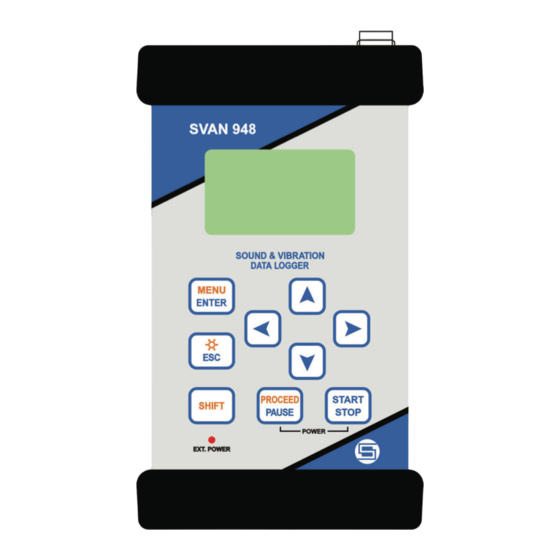
The name given in brackets (...) denotes the second push-button function which is available after pressing in conjunction (or in sequence) the <SHIFT> push-button. The view of the control push-buttons of the SVAN 948 instrument <SHIFT> The second function of a push-button (written in red colour on a push-button) can be used when the <SHIFT>... - Page 15 SVAN 948 USER MANUAL Notice: The operation of this push button can be set as the “Shift” mode or the “2nd Fun.” SETUP SETUP mode in the SHIFT MODE window of the list (see Chapter 5 for the list description).
- Page 16 SVAN 948 USER MANUAL <g>, <h> These push-buttons enable one, in particular, to: • select the options in an active position in the "horizontal direction" (e.g. filter: LIN, A or C, Integration time: 1s, 2s, 3s, … etc.), • select the measurement result to be displayed (e.g. PEAK, MAX, MIN, etc.) in One Profile and 3 PROFILES modes of result’s presentation),...
-
Page 17: Input And Output Sockets Of The Instrument
The full description of the signals connected to the sockets is given in the Appendix C. The view of the top cover of the SVAN 948 instrument in 1:1 scale In the bottom cover three sockets exist: USB (in the figure below in the middle), AC / Int. (in the figure below in the left side) and Ext. - Page 18 Notice: Switch the power off before connecting the instrument to any other device (e.g. a printer or a Personal Computer). The view of the front panel of the SVAN 948 instrument in 1:1 scale 2 - 5...
- Page 19 SVAN 948 USER MANUAL The view of the rear panel of the SVAN 948 instrument in 1:1 scale 2 - 6...
-
Page 20: Setting Of The Instrument
SVAN 948 USER MANUAL 3. SETTING OF THE INSTRUMENT In order to perform the measurements using the instrument the user has only to plug in the preamplifier with the microphone and switch the power on. Notice: The user has to press the <PAUSE> and <START / STOP> push-buttons in parallel in order to switch the power On/Off. - Page 21 SVAN 948 USER MANUAL INPUT The view of the displays with the main list (a) and the elements of the list (b) Next pressing of the <ENTER> push-button enables one to access mentioned above sub-lists. The view of the display with the opened MEASURE SETUP sub-list (path: MENU / INPUT / MEASURE SETUP) The desired position of a list is accessed after pressing the <...
- Page 22 SVAN 948 USER MANUAL The view of the displays during and after the accessing the FREE SPACE window (path: MENU / FILE) In order to close such window the user has to press the <ESC> push-button. In the instrument there are also windows which are used for entering text (i.e.
- Page 23 SVAN 948 USER MANUAL FUNCTION Control diagram of the list INPUT (one of the main lists available after pressing the <MENU> push-button) MEASURE SETUP (sub-list) START DELAY (position); available values of the delay before starting the execution of the §...
- Page 24 SVAN 948 USER MANUAL BUFFERS SETUP: (sub-list) available types of measurement results which has to be saved in the instrument’s buffer from the channels: o None, PEAK, P–P, MAX, RMS - in the case of vibration measurements and o None, PEAK, MAX, MIN, RMS - in the case of sound measurements o VECTOR: available value of VECTOR which has to be saved in the instrument’s buffer...
- Page 25 SVAN 948 USER MANUAL INPUT Control diagram of the list 3 - 6...
- Page 26 SVAN 948 USER MANUAL DISPLAY (one of the main lists available after pressing the <MENU> push-button) DISPLAY MODES (sub-list); it enables the user to activate ([√ √ √ √ ]) or switch off ([ ]) the available modes of result’s presentation SPECTRUM (position);...
- Page 27 SVAN 948 USER MANUAL TOTAL 3: (sub-list) enables one to select the weighted filter to be used for the calculation of the TOTAL value in the third profile: FILTER: (position); available values of the weighted filters: • in the case of sound measurements: LIN, SUSR1, SUSR2, SUSR3 or any other sent to the unit by means of the interface •...
- Page 28 SVAN 948 USER MANUAL Control diagram of the DISPLAY list 3 - 9...
- Page 29 SVAN 948 USER MANUAL FILE (one of the main lists available after pressing the <MENU> push-button) SAVE: [name of the file] or SAVE NEXT: [name of the file]; the name of the file can be fully edited in the FILE NAME window after pressing the <ENTER> push-button in the case of SAVE or can be edited in the simplify way by pressing the <...
- Page 30 SVAN 948 USER MANUAL FILE Control diagram of the list 3 - 11...
- Page 31 SVAN 948 USER MANUAL AUX. FUNCTIONS (one of the main lists available after pressing the <MENU> push-button) HAV/WBV CALC. (position); HAV CALCULATOR (position) it enables to calculate the various H–A parameters: PARTIAL § EAV/ELV, PARTIAL EXPOSURE and DAILY EXPOSURE of vibration. All results are counted according to the selected standard •...
- Page 32 SVAN 948 USER MANUAL AUX. FUNCTION Control diagram of the list 3 - 13...
- Page 33 SVAN 948 USER MANUAL SETUP (one of the main lists available after pressing the <MENU> push-button) TIMER (sub-list) TIME (position); it enables the user to set time of the self switching on of the instrument § RTC (sub-list) RTC (position); it enables the user to set the internal real time clock of the instrument §...
- Page 34 SVAN 948 USER MANUAL … 20.0kHz: available values of 20 kHz centre frequency filter: -100.0dB ... 100.0dB • CLEAR (position) CLEAR enables the user to select which filters should be cleared; the available options are as follows: ALL, SUSR1, SUSR2, SUSR3 or any other STAT.
- Page 35 SVAN 948 USER MANUAL VIBRATION UNITS (sub-list which has the meaning only for vibration measurements) § VIBRATION UNITS (position); it enables the user to set METRIC (e.g. m/s , m/s, m) or NON- METRIC units (e.g. g, ips, mil) WARNINGS (sub-list) RES.NOT SAVE: (position);...
- Page 36 SVAN 948 USER MANUAL 3 - 17...
- Page 37 SVAN 948 USER MANUAL SETUP Control diagram of the list 3 - 18...
-
Page 38: Powering Of The Instrument
SVAN 948 USER MANUAL 3.2. POWERING OF THE INSTRUMENT The SVAN 948 is powered from four internal replaceable AA batteries. For the external power operation an adapter should be connected to the Power socket located on the bottom cover of the instrument. -
Page 39: Initial Setup Of The Instrument
SVAN 948 USER MANUAL 3.3. INITIAL SETUP OF THE INSTRUMENT The instrument passes the self-test after switching on (in this time the producer and the name of the instrument is displayed on the display) and then it enters the sound or vibration mode for channel 1 (depending on which mode was used during the switch off of the unit). - Page 40 SVAN 948 USER MANUAL CHANNEL 3 - VIBR. mode; 316 m/s range; HP10 weighting filter (FILTER: HP10), 1.0 s RMS detector (DETECT.: 1.0s); CHANNEL 4 - SOUND mode; 130 dB range; A weighting filter (FILTER: A), FAST type of the RMS detector (DETECTOR: FAST).
- Page 41 SVAN 948 USER MANUAL - “Vertical bars” icon corresponds to the current input signal level (it is related to the maximum measured value over the last second). The sign Ç Ç Ç Ç means that the level of the signal was from 0.1 dB to 10 dB higher then the current measurement range.
- Page 42 SVAN 948 USER MANUAL Table 3.1. The limits of the signal causing the different icon’s indication in the case of sound measurements 1/1 OCTAVE, 1/3 OCTAVE or FFT ANALYSIS INDICATOR 130 dB range 105 dB range 130 dB range ≥ 137.5 dB ≥...
- Page 43 Notice: In all modes of the instrument the “Clock” icons are always displayed on the display. Notice: In SVAN 948 “Battery’ Icon is displayed if we use an internal battery device (4AA batteries). When the meter is powered by external power supply the “Battery” icon is not displayed on the screen.
-
Page 44: Measurement Functions Of The Instrument
SVAN 948 USER MANUAL 4. MEASUREMENT FUNCTIONS OF THE INSTRUMENT The SVAN 948 is a unique pocket 4-channels instrument combining functions of a sound level meter (SLM), with the Type 1 accuracy (according to IEC 651, IEC 804 and IEC 61672-1 standards), a vibration level meter (VLM), 1/1 OCTAVE and 1/3 OCTAVE real time analyser in which in parallel operate the digital pass-band filters. - Page 45 SVAN 948 USER MANUAL • In the case of the presentation of 1/1 OCTAVE or 1/3 OCTAVE statistical analysis results (see above for the acoustic signal), pressing the <SHIFT> and < > or <SHIFT> and < > push- buttons enables the user to present the results of the analysis for different 1/1 OCTAVE or 1/3 OCTAVE filters.
-
Page 46: Calibration
SVAN 948 USER MANUAL 4.1. CALIBRATION The instrument is factory calibrated with the supplied accelerometer and microphone for standard environmental conditions. Each of four channels should be calibrated separately. For situations where the absolute vibration or sound level value is important, a calibration of the measurement channel should be conducted. -
Page 47: The Calibration By The Sensitivity Introduction
SVAN 948 USER MANUAL 4.1.1. The calibration by the sensitivity introduction Calibration BY SENSITIVITY in the case of vibration signal The calibration by the accelerometer’s sensitivity introduction can be conducted in the following way: 1. Select this type of the calibration (highlight the text BY SENSITIVITY) from the CALIBRATION sub-list and press the <ENTER>... -
Page 48: Calibration By Sensitivity In The Case Of Acoustic Signal
SVAN 948 USER MANUAL The view of the displays with the lowest possible sensitivity and the greatest calibration factor (a) and the greatest sensitivity and the lowest calibration factor (b) Note: The calibration factor is always added to the results in the VIBRATION LEVEL METER mode (VLM), 1/1 OCTAVE, 1/3 OCTAVE and the FFT analysis modes. - Page 49 SVAN 948 USER MANUAL The lowest value of the sensitivity to be able to introduce is equal to 50.0 µV / Pa (it conforms to the calibration factor equal to 60.0 dB) and the greatest one - 50.0 V / Pa (calibration factor equal to -60.0 dB).
-
Page 50: The Calibration By The Measurement
SVAN 948 USER MANUAL 4.1.2. The calibration by the measurement Calibration BY MEASUREMENT in the case of vibration signal The calibration by measurements can be conducted in the following way: 1. Select the calibration by measurement (highlight the text BY MEASUREMENT) from the CALIBRATION sub-list and press the <ENTER>... -
Page 51: Calibration By Measurement In The Case Of Acoustic Signal
(the value of the CAL. LEVEL set by the producer of the SVAN 948 is equal to 94.0 dB). 2. Switch on the calibrator and wait ca 30 seconds before starting the calibration measurement. - Page 52 SVAN 948 USER MANUAL The view of the displays during the calibration measurement Waiting for the start of the measurements the DELAY is counted down on the display and the CALIBRATION text is changing (from big letters to small and vice versa). During the measurements the cal.
-
Page 53: Level Meter
SVAN 948 USER MANUAL 4.2. LEVEL METER The LEVEL METER mode provides the user with the functions of the SLM meeting the IEC 651, IEC 804 and IEC 61672-1 standards for Type 1 accuracy and the functions of VLM meeting the ISO 8041 standard. -
Page 54: Sound Level Meter
SOUND (a) or VIBRATION (b) mode When the SVAN 948 instrument is working as sound level meter, the main results of the channels are presented on the display in the form described below. For each channel the selected result is displayed on the left side followed by its value, units and the type of the detector. - Page 55 SVAN 948 USER MANUAL Notice: The PEAK result never depends on the detector time constant. The results LEQ, SEL and Ld(en) do not depend on the detector time constant if in the RMS INTEGRATION position of the SETUP list the LINEAR option was selected. The results LEQ, SEL and Ld(en) depend on the detector...
-
Page 56: One Profile Mode Of Measurement Results Presentation
SVAN 948 USER MANUAL The view of the displays with the DISPLAY MODES (path: MENU / DISPLAY / DISPLAY MODES) sub-list opened and active all modes of the measurement results presentation (a) and some of the modes switched off (b) One profile mode of measurement results presentation This mode of presentation is treated as main and it can not be switched off. -
Page 57: Profiles Mode Of Measurement Results Presentation
SVAN 948 USER MANUAL The view of the displays in one profile presentation; the switching between the channels 3 PROFILES mode of the measurement results presentation In 3 PROFILES mode of result’s presentation the selected results from each channel are displayed in three consecutive lines. -
Page 58: Presentation Of Time History - Plot
SVAN 948 USER MANUAL Presentation of time history - PLOT The PLOT mode of results presentation is available if data from at least one channel are logged in the buffer’s file. If the BUFFERS position in BUFFERS SETUP sub-list is switched ON but in the selected channel there was nothing switched on ([√... - Page 59 SVAN 948 USER MANUAL If in each channel a selected result is saved, in order to view time history in all channels the user has to press the < > and < > push-buttons. The displays in the PLOT presentation mode; the change of the profile and channels In the PLOT it is possible to shift the horizontal axis in relation to the vertical one using the <SHIFT>...
-
Page 60: Vibration Level Meter
SVAN 948 USER MANUAL 4.2.2. Vibration level meter When the SVAN 948 instrument is working as vibration level meter, the main results of the channels are presented on the display in the form described below. For each channel the selected result is displayed on the left side followed by its value and the units. -
Page 61: One Profile Mode Of Measurement Results Presentation
SVAN 948 USER MANUAL By pressing the < > or < > push-button the user can switch the display mode (the way of the measurement results presentation) to: - One profile, - 3 PROFILES, - PLOT (from the channels in which the results of the measurement were stored in the files of the buffer;... -
Page 62: Profiles Mode Of The Measurement Results Presentation
SVAN 948 USER MANUAL The change of the channel is achieved by pressing the <SHIFT> with < > or <SHIFT> with < > push-buttons. The view of the displays in one profile presentation – the changing of the channels 3 PROFILES mode of the measurement results presentation In 3 PROFILES mode of result’s presentation the selected results from each channel are displayed... - Page 63 SVAN 948 USER MANUAL INPUT / MEASURE SETUP / BUF. STEP)). There are 57 lines presented on the display with the dynamics not greater than 80 dB. The read-out of the interested value can be done using the cursor controlled by the < >, < >...
- Page 64 SVAN 948 USER MANUAL The displays in the PLOT presentation mode; the change of the profile, LOGarithmic scale (path: MENU / setting selected DISPLAY / DISPLAY SETUP / CHANNEL x/ DISPLAY SCALE / LOG) The displays in the PLOT presentation mode; the change of the profile, METRIC...
-
Page 65: Measurement Parameters Setting
SVAN 948 USER MANUAL 4.2.3. Measurement parameters setting INPUT The important parameters for the measurement are programmed by means of the SETUP lists. Measurement parameters setting - INPUT Setting of the channels parameters can be done by means of the... -
Page 66: Selection Of Measurement Parameters - Measure Setup
SVAN 948 USER MANUAL Selection of measurement parameters - MEASURE SETUP All settings made in MEASURE SETUP are common for sound and vibration level meters. The MEASURE SETUP sub-list is opened after the selection of the MEASURE SETUP text from the INPUT list by means of the <... - Page 67 SVAN 948 USER MANUAL - from 1 s to 59 s (with 1 second or 10 seconds step), The view of the displays during the setting of the INT. TIME ; time (path: MENU / INPUT / MEASURE SETUP) expressed in seconds - from 1 m (min) to 59 m (with 1 minute or 10 minutes step) and The view of the displays during the setting of the INT.
-
Page 68: Setting Number Of Repetition Of Measurement Cycles - Rep. Cycle
SVAN 948 USER MANUAL Setting number of repetition of measurement cycles - REP. CYCLE The REP. CYCLE position defines the number of cycles (with the measurement time defined in the INT. TIME) which should be performed by the instrument. The required parameter can be set by means of the <... -
Page 69: Setting Parameters In A Channel - Channel X
SVAN 948 USER MANUAL The view of the sub-lists: CHANNELS SETUP (a) and CHANNEL 2 (b) Setting parameters in a channel - CHANNEL x In the CHANNEL x sub-list the following parameters can be programmed independently for each channel: - mode,... -
Page 70: Selection Of The Weighting Filter In Slm - Filter
SVAN 948 USER MANUAL It is possible to change RANGE in both modes: in SOUND and VIBRATION mode. In the case of acoustic signal the instrument operates in two input ranges 105dB and 130dB, which can be selected by means of the range position. In order to change the mode of the range the user has to press the < >, <... -
Page 71: Selection Of The Weighting Filter In Vlm - Filter
SVAN 948 USER MANUAL • A type 1 according to the IEC 651 and IEC 61672-1 standards, • C type 1 according to the IEC 651 and IEC 61672-1 standards. The view of the displays in the CHANNEL 3 sub-list; the selection of the weighting filter The characteristics of the filters are given in Appendix D. -
Page 72: Selection Of The Rms Detector In Slm - Detector
SVAN 948 USER MANUAL The view of the displays in the PROFILE 2 sub-list; the selection of the weighting filter in the case of velocity measurements • in the case of the displacement measurements: Dil1, Dil3 and Dil10. The view of the displays in the PROFILE 2 sub-list; the selection of the weighting filter in the case of displacement measurements The characteristics of the filters are given in Appendix D. -
Page 73: Selection Of The Measurement Parameters - Buffers Setup
SVAN 948 USER MANUAL and 10.0 s. The selection of the required detector is made with the < >, < > push-buttons. The user can pass to the selection of the next parameter from the CHANNEL x sub-list pressing the < >, < > push- buttons. - Page 74 SVAN 948 USER MANUAL The view of the displays in the CHANNEL x sub-list; the selection of the parameters to be saved in the buffer’s file in the case of vibration mode (a) and sound mode (b) In order to switch parameters in the buffer, the user has to place special character in the chosen position;...
-
Page 75: Selection Of Mode And Triggering Parameters - Trigger Setup
SVAN 948 USER MANUAL Notice: Setting BUFFER:OFF results in bypassing the storing of the given channel’s results in the buffer’s file. It creates more space in the buffer for other channels (see Chapter 5 for details). Notice: The buffer is updated in the time periods (steps) defined in the BUF. STEP (path: The way the measurement results are stored is described MENU/ INPUT/ MEASURE SETUP/ BUF. -
Page 76: Selection Of The Triggering Signal In Slm - Source
SVAN 948 USER MANUAL In the case when the SLOPE + is selected, the measurement starts when the arising signal will pass the level determined in the LEVEL. The measurement is stopped when the conditions set in the MEASURE SETUP sub-list are fulfilled, after pressing the <START / STOP> push-button or after receiving remotely the proper control code. -
Page 77: Setting The Level Of Triggering - Level
SVAN 948 USER MANUAL Setting the level of triggering - LEVEL The level of the triggering ( LEVEL) can be set in 1 dB step (or 10 dB steps) from 24 dB to 136 dB range using the < >, < > push-buttons (or < >, < > with <SHIFT>). - Page 78 SVAN 948 USER MANUAL The view of the displays in the TRIGGER SETUP sub-list ; the setting (path: MENU / INPUT / TRIGGER SETUP) of the POST TRIGGER The value set in the PRE / POST are confirmed and the sub-list is closed after pressing the <ENTER>...
- Page 79 In this position two options are available: FREE (for the measurement performed in the free field conditions) and DIFFUSE (for the measurement performed in the diffuse field conditions). The microphone supplied with the SVAN 948 instrument (SV 22) is designed for the 4 - 36...
- Page 80 SVAN 948 USER MANUAL measurement performed in the free field conditions. In order to make the measurements in the diffuse field conditions the user has to switch on an additional correcting filter. The frequency characteristic of this filter is given in App. D. The FREE option selection means that the correcting filter for the diffuse field conditions is switched off.
-
Page 81: Activation Of Optional Functions
SVAN 948 USER MANUAL 4.3. ACTIVATION OF OPTIONAL FUNCTIONS The wide-band frequency analysis (1/1 OCTAVE or 1/3 OCTAVE) and the narrow-band frequency analysis (FFT) are the optional function broadening the applications of the instrument. The function names are specified in the MEASUR. FUNCTION sub-list of the FUNCTION list. -
Page 82: 1/1 Octave Analyser
SVAN 948 USER MANUAL 4.4. 1/1 OCTAVE ANALYSER The instrument work in parallel four independent sound / vibration level meters channels, which perform the measurement of the signal with the selectable combination – the user can configure each channel separately. -
Page 83: 1/1 Octave Analyser Of Acoustic Signal
SVAN 948 USER MANUAL 4.4.1. 1/1 OCTAVE analyser of acoustic signal In order to select the instrument’s acoustic mode the user has to enter the CHANNELS SETUP list by pressing the <MENU> push-button, selecting by means of the < >, < > (or < >, < >) push-buttons the INPUT text and pressing the <ENTER>, and then enter the CHANNELS SETUP the same way like in... - Page 84 SVAN 948 USER MANUAL Notice: The user can select the number of the currently active modes of the √ √ √ √ measurement results presentation switching on ([ ]) or off ([ ]) the given mode in the DISPLAY MODES...
- Page 85 SVAN 948 USER MANUAL In the PLOT mode the results are presented which are saved in the buffer from the channels (in case when text ON in the BUFFERS positions is selected. The selection of the OFF text means that the results are not saved in the buffer’s file) with the step set for all channels in the BUF.
-
Page 86: Selection Of The Measurement Range In 1/1 Octave Analysis Of Acoustic Signal - Range
SVAN 948 USER MANUAL The spectra registered in the buffer’s file can be presented on the display in the BUFFER VIEW sub-list of the DISPLAY list (path: MENU / DISPLAY / BUFFER VIEW). These spectra are saved with the same step as selected in the SLM profiles (see the description of the BUF. STEP position of the MEASURE SETUP sub-list). -
Page 87: Buffers Setup
SVAN 948 USER MANUAL The view of the displays with the RANGE ( position selected path: MENU / INPUT / CHANNEL x / RANGE) It is possible to change RANGE in SOUND mode. In this case the instrument operates in two input ranges 105dB and 130dB, which can be selected by means of the range position. - Page 88 SVAN 948 USER MANUAL The view of the displays in the BUFFERS SETUP sub-list ( ; the selection path: MENU / INPUT / BUFFERS SETUP) of the BUFFERS store The user can select the following results, which can be saved: PEAK, MAX, MIN and RMS in the case of sound measurement.
-
Page 89: Selection Of 1/1 Octave Analysis Parameters For Acoustic Signal - Spectrum
SVAN 948 USER MANUAL Selection of 1/1 OCTAVE analysis parameters for acoustic signal – SPECTRUM The SPECTRUM sub-list (path: MENU / INPUT / 1/1 OCTAVE SETUP / CHANNEL x / SPECTRUM) is a context element, which appears on the INPUT sub-list in 1/1 OCTAVE or 1/3 OCTAVE mode. Using the SPECTRUM sub-list one can select in 1/1 OCTAVE analysis the weighting filter and the result which has to be saved in the buffer’s file of the instrument. -
Page 90: Selection Of 1/1 Octave Analysis Result To Be Saved In The Buffer's File - Buffer
SVAN 948 USER MANUAL Selection of 1/1 OCTAVE analysis result to be saved in the buffer’s file - BUFFER position The RMS or LEQ (when the user select A filter in FILTER position in SPECTRUM sub-list) result from 1/3 OCTAVE analysis can be saved in the buffer’s file of the instrument. The selection of the required result is made with the <... - Page 91 SVAN 948 USER MANUAL 1/1 OCTAVE filters, starting from 125 Hz (125 Hz, 250 Hz, 500 Hz, 1.00 kHz, 2.00 kHz, 4.00 kHz, 8.00 kHz and 16.0 kHz), are available as well as MAX result from the selected channel. The view of the displays in TRIGGER SETUP window; the selection of the signal used for triggering...
-
Page 92: 1/1 Octave Analyser Of Vibration Signal
SVAN 948 USER MANUAL 4.4.2. 1/1 OCTAVE analyser of vibration signal In order to select the instrument’s acoustic mode the user has to enter the CHANNELS SETUP list by pressing the <MENU> push-button, selecting by means of the < >, < > (or < >, < >) push-buttons the INPUT text and pressing the <ENTER>, and then enter the CHANNELS SETUP the same way like in... - Page 93 SVAN 948 USER MANUAL Notice: The user can select the number of the currently active modes of the √ √ √ √ measurement results presentation switching on ([ ]) or off ([ ]) the given mode in the DISPLAY MODES...
- Page 94 SVAN 948 USER MANUAL • which name and coefficients are sent to the instrument using the unit’s interface and special functions described in App. A. The view of the displays with the settings influencing the TOTAL values presented in the SPECTRUM mode in selected CHANNEL The third TOTAL value is measured with the weighting filter: •...
- Page 95 SVAN 948 USER MANUAL The view of the displays in 1/1 OCTAVE analysis in the SPECTRUM display mode, LINear (path: MENU / DISPLAY / DISPLAY SETUP / CHANNEL x / DISPLAY SCALE / LIN) vibration scale, METRIC (path: MENU / SETUP /...
-
Page 96: Measurement Range Selection In 1/1 Octave Analysis Of Vibration Signal - Range
SVAN 948 USER MANUAL The view of the displays in 1/1 OCTAVE analysis in the PLOT mode; the registered results from all profiles In the SPECTRUM mode it is possible to shift the horizontal axis in relation to the vertical one of the presented results using the <SHIFT>... -
Page 97: Buffers Setup
SVAN 948 USER MANUAL It is possible to change RANGE in VIBRATION mode. In this case the instrument operates in two input ranges 117.8 m/s and 316 m/s , which can be selected by means of the range position. In order to change the mode of the range the user has to press the <... -
Page 98: Selection Of 1/1 Octave Analysis Parameters For Vibration Signal - Spectrum
SVAN 948 USER MANUAL The user can select the following results, which can be saved: PEAK, P–P, MAX and RMS in the case of vibration measurement. The selection of the parameter from the CHANNEL x sub-list is made by pressing the < >, < > push-buttons. After pressing the <ENTER> push-button any changes made in the sub-list are confirmed and the sub-list is closed. -
Page 99: Buffer
SVAN 948 USER MANUAL The view of the displays in the 1/1 OCTAVE SETUP window with the SPECTRUM text selected in CHANNEL x position User can switch OFF or ON SPECTRUM position in selected channels by pressing the < > or <... -
Page 100: Selection Of The Result Which Triggers Registration In Buffer Mode In 1/1 Octave Analysis Of Vibration Signal
SVAN 948 USER MANUAL Selection of the result which triggers registration in BUFFER mode in 1/1 OCTAVE analysis of vibration signal In level meter mode only the result coming from the RMS detector of the one channel is used for triggering purposes. -
Page 101: 1/3 Octave Analyser
SVAN 948 USER MANUAL 4.5. 1/3 OCTAVE ANALYSER In order to select the 1/3 OCTAVE analysis mode the user has to enter the FUNCTION list by pressing the <MENU> push-button, selecting by means of the < >, < > (or < >, < >) push-buttons the FUNCTION text and pressing the <ENTER>. -
Page 102: 1/3 Octave Analyser Of Acoustic Signal
SVAN 948 USER MANUAL 4.5.1. 1/3 OCTAVE analyser of acoustic signal CHANNELS SETUP In order to select the instrument’s acoustic mode the user has to enter the list by pressing the <MENU> push-button, selecting by means of the < >, < > (or < >, < >) push- buttons the INPUT text and pressing the <ENTER>, and then enter the CHANNELS SETUP the same... - Page 103 SVAN 948 USER MANUAL In order to change the mode of the measurement results presentation the user has to press the < > or the < > push-buttons. The following modes are available: One profile, SPECTRUM, 3 PROFILES, STATISTICS and PLOT.
- Page 104 SVAN 948 USER MANUAL position to display in PLOT mode (user can switched on ([√ √ √ √ ] selected position to display in PLOT mode) with the step set for all channels in the BUF. STEP position. The active channel is changed after pressing the <...
-
Page 105: Range
SVAN 948 USER MANUAL same step as selected in the SLM profiles (see the description of the BUF. STEP position of the MEASURE SETUP sub-list). In order to display the registered in the buffer’s file spectra the user has to: - press the <... - Page 106 SVAN 948 USER MANUAL The view of the displays with the RANGE ( position selected path: MENU / INPUT / CHANNEL x / RANGE) It is possible to change RANGE in SOUND mode. In this case the instrument operates in two input ranges 105dB and 130dB, which can be selected by means of the range position.
- Page 107 SVAN 948 USER MANUAL The view of the displays in the BUFFERS SETUP sub-list ( , the selection path: MENU / INPUT / BUFFERS SETUP) of the BUFFER position The user can select the following results, which can be saved: PEAK, MAX, MIN and RMS in the case of sound measurement.
-
Page 108: Buffers Setup
SVAN 948 USER MANUAL Notice: It is not possible to change the values of the parameters during the execution of the measurements. It is possible to open different lists and sub-lists but the positions in these lists are not displayed inversely and so - not accessible. The “Loudspeaker” icon indicates that the instrument is in the measurement process. -
Page 109: Selection Of The Weighting Filter In 1/3 Octave Analysis Of Acoustic Signal - Filter Position
SVAN 948 USER MANUAL Selection of the weighting filter in 1/3 OCTAVE analysis of acoustic signal - FILTER position The following weighting filters are available in 1/3 OCTAVE analysis: • A type 1 according to the IEC 651 and IEC 61672-1 standards, •... -
Page 110: Selection Of The Result Which Triggers Registration In Buffer Mode In 1/3 Octave Analysis Of Acoustic Signal
SVAN 948 USER MANUAL The view of the displays with not accessible parameters of the PROFILES SETUP lists (path: MENU / INPUT / 1/3 OCTAVE SETUP) Notice: All other settings of the instrument are common for 1/3 OCTAVE analyser and the SLM. -
Page 111: 1/3 Octave Analyser Of Vibration Signal
SVAN 948 USER MANUAL 4.5.2. 1/3 OCTAVE analyser of vibration signal In order to select the instrument’s vibration mode the user has to enter the CHANNELS SETUP sub-list by pressing the <MENU> push-button, selecting by means of the < >, < > (or < >, < >) push-buttons the INPUT text and pressing the <ENTER>, and then enter the CHANNELS SETUP the... - Page 112 SVAN 948 USER MANUAL One Profile, 3 PROFILES and PLOT display modes are the same as for the VLM. The SPECTRUM mode displays 1/3 OCTAVE analysis results (so-called spectrum) together with three TOTAL RMS values measured with the weighting filters. Those filters are set in the TOTAL VALUES sub- list of the DISPLAY SETUP list (path: MENU / DISPLAY / DISPLAY SETUP / CHANNEL x / TOTAL VALUES).
- Page 113 SVAN 948 USER MANUAL The view of the displays with the settings influencing the TOTAL values presented in the SPECTRUM mode in selected CHANNEL The third TOTAL value is measured with the weighting filter: • selected in the third channel (CH) or •...
- Page 114 SVAN 948 USER MANUAL The view of the displays in 1/3 OCTAVE analysis with the acceleration, velocity and displacement spectrum expressed in LINear (path: MENU / DISPLAY / DISPLAY SETUP / CHANNEL x / DISPLAY SCALE / LIN), METRIC units...
- Page 115 SVAN 948 USER MANUAL The view of the displays in 1/3 OCTAVE analysis with the acceleration, velocity and displacement spectrum expressed in LOGarithmic units (path: MENU / DISPLAY / DISPLAY SETUP / DISPLAY SCALE / LOG) The view of the displays in 1/3 OCTAVE analysis with the acceleration spectrum expressed in LINear...
- Page 116 SVAN 948 USER MANUAL The view of the displays in 1/3 OCTAVE analysis with the acceleration spectrum expressed in LINear, METRIC units; the first TOTAL value selected as HP acceleration filter; the second TOTAL value selected as CH 2 and one of the displacement filters (Dil1) selected there or TOTAL 2 selected as USER VIBRATION filter;...
- Page 117 SVAN 948 USER MANUAL In one profile and 3 PROFILES modes the results are presented in the same way as in the case of the VLM mode with only one difference that instead of the continuous line the doted one is used. The active channel is changed after each pressing of the <SHIFT>...
-
Page 118: Measurement Range Selection In 1/3 Octave Analysis Of Vibration Signal - Range
SVAN 948 USER MANUAL The spectra registered in the buffer’s file can be presented on the display in the BUFFER VIEW sub-list of the DISPLAY list. These spectra are saved with the same step as selected in the VLM profiles (see the description of the BUF. -
Page 119: Buffers Setup
SVAN 948 USER MANUAL The view of the displays with RANGE position (path: MENU / INPUT / CHANNEL x / RANGE) not accessible. Notice: If an OVERLOAD occurs it is signalled by the ”Bell” icon (cf. Chapter 3 for details). -
Page 120: Selection Of 1/3 Octave Analysis Parameters For Vibration Signal - Spectrum
SVAN 948 USER MANUAL The view of the displays in the BUFFERS SETUP sub-list; the all the parameters were selected to be saved in the buffer’s file; in CHANNEL 1 and 2 vibration and in CHANNEL 3 and 4 sound parameters Notice: The change of the channels parameters is not possible when the measurement is performed. -
Page 121: Buffer
SVAN 948 USER MANUAL Selection of 1/3 OCTAVE analysis result of vibration signal to be saved in the buffer’s file - BUFFER The RMS result from 1/3 OCTAVE analysis can be saved in the buffer’s file of the instrument. The selection of the required result is made with the <... - Page 122 SVAN 948 USER MANUAL … The view of the displays in TRIGGER SETUP window; the selection of the signal used for triggering purposes in BUFFER mode; METRIC units selected Notice: It is not possible to change the values of the parameters during the execution of the measurements.
-
Page 123: Dose Analyser
SVAN 948 USER MANUAL 4.6. DOSE analyser Generally, most of the SVAN 948 features are similar to the VLM mode. When the SVAN 948 instrument is working as DOSE METER, the main results of the channels are presented on the display in the form described below. - Page 124 SVAN 948 USER MANUAL For the second display after consecutive pressing of the < >, < > push-buttons there is a possibly to see: • CURRENT EXPOSURE, DAILY EXPOSURE, CURRENT DOSE, DAILY DOSE, EAV TOTAL TIME, TIME LEFT TO EAV, ELV TOTAL TIME and TIME LEFT TO ELV in the case of the WBV mode and •...
- Page 125 SVAN 948 USER MANUAL • EAV TOTAL TIME - shows the time to achieve the EAV limits of vibration, based on CURRENT EXPOSURE. The limit is defined in STANDARD. • TIME LEFT TO EAV - shows the remaining time to achieve the EAV limits of vibration based on CURRENT EXPOSURE.
-
Page 126: Profiles Mode Of The Measurement Results Presentation
SVAN 948 USER MANUAL 3 PROFILES mode of the measurement results presentation In 3 PROFILES mode of result’s presentation the selected results from each channel are displayed in three consecutive lines. In each line the name of the measurement result, its value and the units are presented. -
Page 127: Hav And Wbv Measurement Parameters Setting
SVAN 948 USER MANUAL 4.6.1. HAV and WBV measurement parameters setting INPUT The important parameters for the measurement are programmed by means of the SETUP lists. Measurement parameters setting - INPUT Setting of the channels parameters can be done by means of the... -
Page 128: Setting Parameters In Channels And For Octave Analysis - Channels Setup
SVAN 948 USER MANUAL Setting parameters in channels and for octave analysis - CHANNELS SETUP The user enters the CHANNELS SETUP sub-list after pressing the <ENTER> push-button on the displayed inversely CHANNELS SETUP text. This sub-list in the case of sound or vibration level meter mode consists of four CHANNEL x sub-lists (each for one channel). -
Page 129: Selection Of The Measurement Range - Range
SVAN 948 USER MANUAL If the user selects a wrong MODE, it shows the text: VEC. DISABLED IN: x ,BAD MODE before the execution of measurement on the display and measurements of dose will not be done. Otherwise the measurement continues. -
Page 130: Selection Of The Weighting Filter In Vlm - Filter
SVAN 948 USER MANUAL The view of the displays with RANGE position ( not accessible. path: MENU / INPUT / CHANNEL x / RANGE) Notice: If an OVERLOAD occurs it is signalled by the ”Bell” icon (cf. Chapter 3 for details). -
Page 131: Selection Of The Rms Detector In Vlm - Detector
SVAN 948 USER MANUAL Selection of the RMS detector in VLM - DETECTOR In the instrument’s VLM mode the selection of the required detector is made with the < >, < > push-buttons. The following detectors are available: 100 ms, 125 ms, 200 ms, 500 ms, 1.0 s, 2.0 s, 5.0 s and 10.0 s. - Page 132 SVAN 948 USER MANUAL The view of the displays in the CHANNEL 1 sub-list; the selection of the parameters to be saved in the buffer’s file In order to switch parameters in the buffer, the user has to place special character in the chosen position;...
-
Page 133: Auxiliary Functions
SVAN 948 USER MANUAL 5. AUXILIARY FUNCTIONS 5.1. DATA AVAILABLE ON THE DISPLAY - DISPLAY LIST In order to open the DISPLAY list the user has to: • press the <MENU> push-button, • select from the main list, using the < >, < > (or < >, < >) push-buttons, the DISPLAY text (highlight it inversely), •... - Page 134 SVAN 948 USER MANUAL is made by placing or replacing the special character in the inversely displayed position of the DISPLAY MODES sub-list by means of the < >, < > push-buttons. In order to confirm the selection the user has to press the <ENTER> push-button. The mode of the displaying the results is related with the selection of the instrument’s function (SLM or VLM, 1/1 OCTAVE, 1/3 OCTAVE or FFT analyser).
-
Page 135: Selection Of The Parameters In Graphical Results Presentation - Display Setup
SVAN 948 USER MANUAL The view of the display in the PLOT mode when there is nothing in the buffer to be displayed (after setting PLOT as active) Each position of the DISPLAY MODES sub-list can be switched on or off independently. The sub-... -
Page 136: Scaling Of The Vertical Axis Of The Graphical Presentation - Dynamic
SVAN 948 USER MANUAL Selection of the scale in graphical results presentations - DISPLAY SCALE The DISPLAY SCALE path: MENU / DISPLAY / DISPLAY SETUP / CHANNEL x / DISPLAY SCALE) sub-list enables the user to change the scale in the available modes of graphical presentation of the measurement results (time history in the PLOT and so-called spectra in the SPECTRUM). -
Page 137: Selection Of The Weighted Filters - Total Values
SVAN 948 USER MANUAL Selection of the weighted Filters - TOTAL VALUES The TOTAL VALUES (path: MENU / DISPLAY / DISPLAY SETUP/ CHANNEL x / TOTAL VALUES) sub- list which is available only in 1/1 OCTAVE or 1/3 OCTAVE analysis; enables the user to select the weighted filters. -
Page 138: Selection Of The Weighted Filters For The 2
SVAN 948 USER MANUAL v CAL. F.: (position available only for vibration measurements); accessible if VUSR1, VUSR2, or VUSR3 was selected in the FILTER position; if the HP filter was selected this position is not displayed; available values (from -60.0dB to 60.0dB with 0.1dB step by pressing the < >, < >... -
Page 139: Selection Of Spectrum Type - Spectrum Type
SVAN 948 USER MANUAL v FILTER: (position); available values of the weighted filters: o in the case of sound measurements: LIN, SUSR1, SUSR2, SUSR3 or any other sent to the unit by means of the interface, The view of the displays with the TOTAL 3 list opened in the case of sound measurements o in the case of vibration measurements: CH, VUSR1, VUSR2, VUSR3 or any other sent to the unit by means of the interface. -
Page 140: Selection Of The Buffer's File To The Display Presentation - Buffer View
SVAN 948 USER MANUAL The view of the display with the SPECTRUM TYPE with the available values for SOUND measurements Selection of the buffer’s file to the display presentation - BUFFER VIEW The BUFFER VIEW sub-list enables the user to examine the contents of the buffer. In order to open this sub-list the user has to press the <ENTER>... - Page 141 SVAN 948 USER MANUAL The contents of the selected file from the buffer is displayed after pressing the <ENTER> push- button. The cursor position is changed after pressing the < >, < > push-buttons. The type of the registered result, the number of the channel the result is coming from, the related time from the beginning of the registration, the value with the units and the indicator of the filter are presented on the right side of the display.
- Page 142 SVAN 948 USER MANUAL … The view of the displays with the selected file from the buffer; the change of the result after pressing < > or < > push-button The spectra are registered in the file’s buffer with the same step as selected in the BUF. STEP position of the MEASURE SETUP sub-list.
- Page 143 SVAN 948 USER MANUAL The view of the displays with the selected file from the buffer containing spectra; the TOTAL values and their time histories Settings of the meter: DISPLAY SCALE: LOGarithmic (path: MENU / DISPLAY / DISPLAY SETUP / CHANNEL x / DISPLAY SCALE / LOG), TOTAL 1: HP (path: MENU / DISPLAY / DISPLAY SETUP / CHANNEL x / TOTAL VALUES / TOTAL 1);...
-
Page 144: Checking The State Of The Internal Battery - Battery
SVAN 948 USER MANUAL The view of the displays with the selected file from the buffer containing spectra; the change between time history and spectra after pressing <ENTER> push-button for 500 Hz filter Additionally, during the presentation of the results saved in the buffer, the dynamic of the drawing can be changed. -
Page 145: Setting The Contrast Of The Display - Contrast
SVAN 948 USER MANUAL the graphical form). The position is opened after pressing the <ENTER> push-button on the highlighted (displayed inversely) BATTERY text. The view of the displays with the BATTERY position when the external supplier is not connected If the instrument is switched on when the external supplier is connected the special message is displayed in the BATTERY position. -
Page 146: Setting The Backlight Parameters - Backlight
SVAN 948 USER MANUAL The view of the displays with the CONTRAST position; the change of the display contrast Setting the backlight parameters - BACKLIGHT The BACKLIGHT (path: MENU / DISPLAY / BACKLIGHT) sub-list enables one to set the parameters of the backlight of the display and the keyboard (using the <... -
Page 147: Checking Specification Of The Instrument - Unit Label
SVAN 948 USER MANUAL The view of the displays in the BACKLIGHT sub-list; the BRIGHTNESS position active DISPLAY The position is closed and the instrument returns to the list after pressing the <ESC> or <ENTER> push-button. Checking specification of the instrument - UNIT LABEL The UNIT LABEL position (path: MENU / DISPLAY / UNIT LABEL) displays the type of the instrument, its serial number and the current software version installed in it. -
Page 148: Setup Menu
SVAN 948 USER MANUAL 5.2. SETUP MENU SETUP (path: MENU / SETUP) list contains different sub-lists and positions. Some of them are directly related with sound measurements, some of them depend on the mode of the instrument (sound or vibration meter) and some are related with the settings of the instrument’s hardware components. In order... -
Page 149: Programming Of The Instrument's Internal Timer - Timer
SVAN 948 USER MANUAL Pressing the <SHIFT> and < > (or <SHIFT> and < >) push-buttons results in a movement to the first position of the opened list and pressing the <SHIFT> and < > (or <SHIFT> and < >) results in a movement to the last position of the opened list. -
Page 150: Programming Of The Instrument's Internal Real Time Clock - Rtc
SVAN 948 USER MANUAL Notice: The new value of a parameter is confirmed after each pressing of the < > or < > together with the <SHIFT> push-buttons (new value is selected without any confirmation from the <ENTER> push-button). SETUP The position is closed and the instrument returns to the list after pressing the <ENTER>... -
Page 151: Introduction The Filter Coefficients For 1/3 (1/1) Octave Analysis - User Filters
DIFFUSE (for the measurement performed in the diffuse field conditions). The microphone supplied with the SVAN 948 instrument (SV 22) is designed for the measurement performed in the free field conditions. In order to make the measurements in the diffuse field conditions the user has to switch on an additional correcting filter. - Page 152 SVAN 948 USER MANUAL • VIEW o VIEW enables the user to select which filter should be viewed; the available options are VUSR1, VUSR2, VUSR3 and any other transmitted to the instrument from a PC by means of the interface After pressing the <ENTER>...
-
Page 153: Setting The Coefficients Of The User Filters Set - Edit (Position)
SVAN 948 USER MANUAL <ESC> push-button (ignoring a change made in the position). After pressing the <ENTER> push-button on the displayed inversely text the proper sub-list is opened. The display’s view in the USER FILTERS sub-list in vibration measurements, the selection of the position Setting the coefficients of the user filters set - EDIT (position) After pressing the <ENTER>... -
Page 154: Selection Of Statistics Levels T Be Saved In A File - Stat. Levels
SVAN 948 USER MANUAL The view of the displays in the CLEAR position in vibration measurements Selection of statistics levels to be saved in a file - STAT. LEVELS The STAT. LEVELS (path: MENU / SETUP / STAT. LEVELS) sub-list enables the user to select ten statistics from one hundred calculated in the instrument to be saved in a file together with the main results of the measurements. - Page 155 SVAN 948 USER MANUAL This position enables the user to set the proper external device. In order to enter this position the SETUP user has to select the EXT. I/O SETUP text in the list, using the < >, < > (or < >, < >) push- buttons, and press the <ENTER>.
-
Page 156: Selection Of Few Push-Buttons Mode - Shift Mode
SVAN 948 USER MANUAL Selection of few push-buttons mode - SHIFT MODE The SHIFT MODE (path: MENU / SETUP / SHIFT MODE) sub-list enables the user to programme the operation mode of the <SHIFT> and <START / STOP> push-buttons. SETUP... -
Page 157: Return To The Factory Made Settings - Clear Setup
SVAN 948 USER MANUAL In order to select a desired mode of the <START / STOP> push-button the < >, < > should be pressed. In order to confirm the selection the <ENTER> push-button has to be pressed. Such pressing closes the sub-list. -
Page 158: Selection Of Detector's Type In The Leq (Rms) Calculations - Rms Integration
SVAN 948 USER MANUAL The window is closed and the instrument returns to the SETUP list after pressing any push-button with an exception of the <SHIFT> one. Selection of detector’s type in the LEQ (RMS) calculations - RMS INTEGRATION The RMS INTEGRATION (path: MENU / SETUP / RMS INTEGRATION) position enables the user to select the detector type for the calculations of the LEQ function (in the case of sound measurements) or the RMS function (in the case of vibration measurements). -
Page 159: Setting The Reference Level Of The Acceleration Signal - Acc
SVAN 948 USER MANUAL are taken into account during the calculations of the measurement results expressed in the logarithmic scale (with the dB as the units). In order to enter this position the user has to select the REFERENCE LEVEL text in the SETUP list, using the <... -
Page 160: Selection Of The Vibration Units - Vibration Units
SVAN 948 USER MANUAL The display’s view in the REFERENCE LEVEL sub-list; the reference level setting of displacement signal In the case of sound measurements the REFERENCE LEVEL sub-lists is used only to inform the user that the reference level of the acoustic signal is equal to 20 µPa. After pressing the <ESC> or <ENTER>... -
Page 161: Selection Of The Warnings - Warnings
SVAN 948 USER MANUAL Selection of the warnings - WARNINGS The WARNINGS (path: MENU / SETUP / WARNINGS) sub-list enables the user to select the messages which could be displayed during the operation of the instrument. In order to enter this sub-list... -
Page 162: Selection Of The Vector Coefficient - Vector Def
SVAN 948 USER MANUAL Selection of the vector coefficient - VECTOR DEF. The VECTOR DEF. position (path: MENU / SETUP / VECTOR DEF.) is used to select the coefficient needed to calculate vibration vector. The values presented below are taken into account during the calculations of the measurement results. -
Page 163: Selection Of The Vibration Dose - Hav/Wbv Dose
SVAN 948 USER MANUAL changes made in the sub-list are confirmed and the sub-list is closed. The return to the SETUP sub-list ignoring any changes made in the sub-list after pressing the <ESC> push-button. The view of the displays in the VECTRO DEF. - Page 164 SVAN 948 USER MANUAL In each available position any change is performed by means of the < >, < > push-buttons. In order to confirm the selection the <ENTER> push-button has to be pressed. After this confirmation the opened window or list is closed. In order to ignore any changes made in the opened window or list the user has to press the <ESC>...
- Page 165 SVAN 948 USER MANUAL The view of the display with maximum EXPOSURE TIME Notice: It is possible to change the time during the execution of the measurements. Selection of the parameters of vibration dose - AXIS SETUP In the AXIS SETUP position path: MENU / SETUP / HAV/WBV DOSE / AXIS SETUP) the user can assign each axis of triaxial accelerometer to the number of channels.
-
Page 166: Selection Of The Standard Of Vibration Dose - Standards
SVAN 948 USER MANUAL The view of the displays informed about wrong selected setting Selection of the standards of vibration dose - STANDARDS The STANDARDS (path: MENU / SETUP / HAV/WBV DOSE / STANDARDS) position enables the user to select standard of the measurement of vibration dose. Selected standard determines the limits of measured vibration. - Page 167 SVAN 948 USER MANUAL is introduced by pressing the <SHIFT> and < > or <SHIFT> and < > push-buttons. In the case of WB limits, the user can change the units too. The view of the displays in the STANDARDS window for USER standard, the selection of the limits value The view of the displays in the STANDARDS window for USER standard, the selection of the unit’s position...
-
Page 168: Saving The Measurement Results
The capacity of available memory is equal to 32 MB. Saving files In the case of the SVAN 948 instrument there are six different types of files containing data: • from Sound Level Meter mode; • from Vibration Level Meter mode;... -
Page 169: Selection Of The File's Operation - File
SVAN 948 USER MANUAL Selection of the file’s operation - FILE Storing the sound measurement results as files in the instrument’s FLASH DISC can be done by FILE means of the list. In order to open this list the user has to: •... -
Page 170: Saving Files In The Instrument's Memory - Save And Save Next
SVAN 948 USER MANUAL Saving files in the instrument’s memory - SAVE and SAVE NEXT The SAVE (path: MENU / FILE / SAVE) position is used for storing data in the internal non-volatile (FLASH DISC) memory as a file (see Appendix B for the file formats). In order to enter this position the... - Page 171 SVAN 948 USER MANUAL The empty space is created for the introduction of a new character in the edited name (the INS operation is executed) when the <SHIFT> push-button is pressed together with the < >. The view of the displays in the FILE NAME edition after pressing the <SHIFT> and < > push-buttons The character, which is displayed inversely, is deleted from the edited name (the Del operation is executed) when the <SHIFT>...
- Page 172 SVAN 948 USER MANUAL performed and there are no results to be saved. The operation can not be done also in a case when the file of the selected name already exists in the instrument’s memory (Fig. b). The instrument then waits for the reaction of the user (any push-button should be pressed except the <SHIFT>...
-
Page 173: Controlling The Data Storing In The Instrument's Memory - Save Options
SVAN 948 USER MANUAL The displays after the file’s name selection (a) and with the message if the REPLACE position is not active (b) Controlling the data storing in the instrument’s memory - SAVE OPTIONS The SAVE OPTIONS (path: MENU / FILE / SAVE OPTIONS) sub-list is used for the selection of the options of data storing in the FLASH DISC memory of the instrument. -
Page 174: Controlling Of The Measurement Statistics Savings - Save Stat
SVAN 948 USER MANUAL the same name if the position is active ([√ √ √ √ ]). The message is displayed that such operation is not available in the case when this position is not active ([ ]) – cf. the description of the SAVE position. The activation or deactivation of the REPLACE position is done by pressing the <... -
Page 175: Loading The Files With The Measurement Results - Load
SVAN 948 USER MANUAL pressing the < >, < > push-buttons. This position was also established in order not to waist too much memory of the instruments when the self saving is not necessary. The displays during the execution of the SAVE OPTIONS – the selection of the AUTO SAVE parameters The window for the edition of the base name for the self saved files is opened (the FILE NAME) after pressing the <ENTER>... - Page 176 SVAN 948 USER MANUAL Notice: It is not possible to load the file during the execution of the measurements. On such attempt the message: „measurement in progress / MEASUREMENT IN PROGRESS” is displayed for about 2 seconds. After pressing the <ENTER> push-button the instrument checks its current state. In the case when the measurements are performed the file loading is impossible.
-
Page 177: Removing A File With The Measurement Results From Memory - Delete
SVAN 948 USER MANUAL The view of the display during the execution of the LOAD operation The next message is displayed after successful end of loading operation. The instrument waits for the reaction of the user (any push-button should be pressed except the <SHIFT> one) and after pressing... -
Page 178: Removing All Files With Measurement Results From Memory - Delete All
SVAN 948 USER MANUAL done pressing the < >, < > push-buttons. After pressing the < > with <SHIFT> push-button the first file is available and after pressing the < > with <SHIFT> push-button - the last one is displayed. The... -
Page 179: Memory Merging - Defragmentation
SVAN 948 USER MANUAL After pressing the <ENTER> push-button the instrument checks its current state. In the case when the measurements are performed, the execution of the DELETE ALL operation is not possible. In such case the message with the changing letters is displayed (see below) and the instrument returns after few seconds to the list from which the DELETE ALL position was called. -
Page 180: Removing All Files With Results From Buffer's Memory - Clear Buffer
SVAN 948 USER MANUAL The view of the displays before the execution of the DEFRAGMENTATION operation The <ENTER> push-button pressing, when the YES option is selected and the instrument is not performing the measurements, merges the memory. The presented below message is displayed in the case when the operation is not required. -
Page 181: Checking The Contents Of The Memory - Catalogue
SVAN 948 USER MANUAL in the buffer. In order to enter this position the user has to select the CLEAR BUFFER text in the FILE list, using the < >, < > (or < >, < >) push-buttons and press the <ENTER>. -
Page 182: Checking The Free Space In The Memory - Free Space
SVAN 948 USER MANUAL In the case when the instrument memory is empty (no file is stored), after entering the CATALOGUE position the NO FILES text is displayed and the instrument waits for the reaction of the user. The user should press then the <ESC>, <ENTER> or <START / STOP> push-button. -
Page 183: Saving Setup In The Instrument's Memory - Save Setup And Save Setup Next
SVAN 948 USER MANUAL Saving setup in the instrument’s memory – SAVE SETUP and SAVE SETUP NEXT The SAVE SETUP (path: MENU / FILE / SAVE SETUP) position is used for storing data in the FLASH DISC memory of the instrument as a file (see Appendix B for the file formats). In order to enter... - Page 184 SVAN 948 USER MANUAL The view of the displays in the FILE NAME edition after pressing the <SHIFT> and < > push-buttons The character, which is displayed inversely, is deleted from the edited name (the Del operation is executed) when the <SHIFT> and < > push-buttons are pressed.
-
Page 185: Loading The Files With The Configuration - Load Setup
SVAN 948 USER MANUAL The data are saved in the file with the name increased by one in relation to the name displayed after SAVE NEXT text after pressing the <ENTER> push-button (if the instrument is not measuring and there are the results to be stored). - Page 186 SVAN 948 USER MANUAL FILE The view of the displays in the sub-list with the LOAD SETUP text highlighted (displayed inversely) Notice: It is not possible to load the file during the execution of the measurements. On such attempt the message: „measurement in progress / MEASUREMENT IN PROGRESS” is displayed for about 2 seconds.
- Page 187 SVAN 948 USER MANUAL The name of the file is accepted and the file is loaded after pressing the <ENTER> push-button. The message is displayed with the name of the selected file during the execution of the operation i.e.: The view of the display during the execution of the LOAD operation The next message is displayed after successful end of loading operation.
-
Page 188: Operations In Buffer
SVAN 948 USER MANUAL Operations in buffer The buffer is the selected part of the instrument’s memory dedicated for storing the huge number of the measurement results. Its capacity is ca 3.4 Mbytes (for the unit with 8 MB of internal memory). The buffer operation is strongly dependent on the operation mode of the instrument (the selected function). - Page 189 SVAN 948 USER MANUAL EXAMPLE 3. To force the every second spectra logging in a file of the buffer without the results measured in three profiles the user has to set: MEASURE SETUP sub-list INT. TIME: <any value>, REP. CYCLE: <any value>, BUF.
- Page 190 SVAN 948 USER MANUAL 5.4. CALCULATION OF THE DOSE PARAMETERS - AUX. FUNCTIONS AUX. FUNCTIONS In order to open the list the user has to: • press the <MENU> push-button, • select from the main list, using the < >, < > (or < >, < >) push-buttons, the AUX. FUNCTIONS text (highlight it inversely), •...
- Page 191 SVAN 948 USER MANUAL RESULTS SEL. position which enables the user to select files with measurement’s results with H-A data; PARTIAL EAV/ELV position which displays the partial result of dose; PARTIAL EXP. position which displays the result of exposure; DAILY EXPOSURE position which displays the result of daily exposure.
- Page 192 SVAN 948 USER MANUAL The view of the displays during the execution of the selected file operation The current file is displayed in the first line. The name of the file is displayed inversely in the second line. The change of the current file with the unit step can be done after pressing the < >, < > push- buttons.
- Page 193 SVAN 948 USER MANUAL The PARTIAL EAV/ELV position (path: MENU / AUX. FUNCTIONS / HAV/WBV CALC. / HAV CALCULATOR / PARTIAL EAV/ELV) is used to display partial results, for each file separately. The results are displayed in two columns – the first column for EAV results and the second for ELV results.
- Page 194 SVAN 948 USER MANUAL The user can rewind the EXPOSURE list and EAV/ELV list using the < >, < >. The return to the HAV CALCULATOR sub-list is possible after pressing the <ESC> push-button. The view of the display with the EXPOSURE and EAV/ELV results for selected file Selection of the daily exposure - DAILY EXPOSURE The DAILY EXPOSURE.
- Page 195 SVAN 948 USER MANUAL The user can select available position select from the main list, using the < >, < > (or < >, < >) push-buttons, the display text is highlight inversely, In order to confirm the selection the <ENTER>...
- Page 196 SVAN 948 USER MANUAL The current file is displayed in the first line. The name of the file is displayed inversely in the second line. The change of the current file with the unit step can be done after pressing the < >, < > push- buttons.
- Page 197 SVAN 948 USER MANUAL The view of the display in the WBV CALCULATOR sub-list the PARTIAL EAV/ELV text highlighted (displayed inversely) The view of the display with the empty partial result list (a), the selecting file in RESULT SEL. sub-list (b) and the PARTIAL EAV/ELV results for selecting file (b), (c) The user can rewind the RESULTS SEL.
- Page 198 SVAN 948 USER MANUAL Selection of the daily result - DAILY RESULTS DAILY RESULTS. position (path: MENU / AUX. FUNCTIONS / HAV/WBV CALC. / WBV CALCULATOR / DAILY EXPOSURE) is used to display DAILY EXPOSURE and DAILY DOSE results, for each selected file separately. The result is calculated relatively to EXPOSURE TIME. The position is opened after pressing the <ENTER>...
Need help?
Do you have a question about the SVAN 948 and is the answer not in the manual?
Questions and answers