
Related Manuals for King Pigeon S273

Summary of Contents for King Pigeon S273
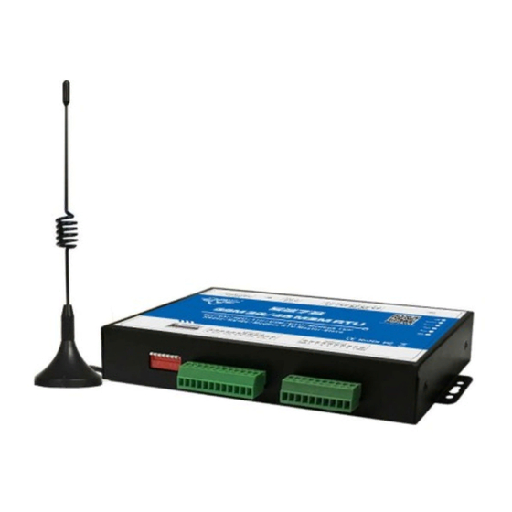
- Page 1 Cellular IoT Modbus RTU S273/S274/S275 User Manual Ver 1.0 Date Issued: 2018-06-18 King Pigeon Hi-Tech. Co., Ltd. www.GPRS-M2M.com...
-
Page 2: Table Of Contents
We recommend that the advice of a registered electrician be sought before any Installation work commences. King Pigeon Hi-Tech.Co., Ltd, its employees and distributors, accept no liability for any loss or damage including consequential damage due to reliance on any material contained in this handbook. -
Page 3: Brief Introduction
TCP/UDP protocol, or integrated to SCADA systems by standard Modbus TCP protocol, too. This is very useful if you need remote control onsite devices with low cost solution. Page 3 of 68 King Pigeon Hi-Tech. Co., Ltd. Ver 1.0... -
Page 4: Safety Directions
Gateway X1; AC/DC Adaptor X1; GSM/3G/4G Antenna X1;User Manual X1; PC Configurator X1 . Note: The package does not include any SIM card. Optional: 35mm Standard DIN rail fixed Bracket Page 4 of 68 King Pigeon Hi-Tech. Co., Ltd. Ver 1.0... -
Page 5: Mainly Features
Support SMS, dial, GPRS, 3G , 4G network for alert, USB port for configuration and upgrade firmware; Inbuilt large capacity automatically rechargeable backup battery, alert when external power failure; Support TCP/UDP, Modbus TCP, Modbus RTU over TCP, King Pigeon IoT RTU protocol and data transparent transmission function;... -
Page 6: Physical Layout And Installation Diagram
Supporting 3V and 1.8V SIM Card External antenna SMA Antenna interface, 50 Ohm, Gain: 3dB Serial Interfaces 1 USB Port SMS, GPRS UDP,TCP, Modbus RTU over TCP and King Pigeon RTU Protocols protocol. 1 RS485, Support Transparent transmission and Modbus RTU Slave, RS485 Modbus RTU Master. - Page 7 When transmitting data by RS485, the LED will flick, otherwise, it is off. Backside Switch & Button Definition SIM Card Slot For SIM Card Installation, only supports 1.8V/3V SIM Card Power Switch For switch ON or OFF the RTU Page 7 of 68 King Pigeon Hi-Tech. Co., Ltd. Ver 1.0...
- Page 8 The 1st Channel Analog input. + stands for positive electrode, - stands for negative 0+/0- electrode. The 2 Channel Analog input. + stands for positive electrode, - stands for negative 1+/1- ~5+/5- electrode. Digital Input Definition Page 8 of 68 King Pigeon Hi-Tech. Co., Ltd. Ver 1.0...
-
Page 9: Settings & Operations
LED Definitions, keep switch on it during the programming. The PC Configuration in the CD, please click it to run it. Also can download from www.GPRS-M2M.com under S273/4/5 page directly. Below is the steps to setup the parameters by PC Configuration, please follow it step by step. - Page 10 Step6: Run the Configurator (Compatible with Windows XP/7/8/10) Tips: In some computer, it required download net framework 4.0 while installation, then please click “Yes” to go to Microsoft website to download this service pack. Page 10 of 68 King Pigeon Hi-Tech. Co., Ltd. Ver 1.0...
- Page 11 Details please check the picture as below: Tips: If not connect successfully, will not enter into next step. Pls check if USB connect well, or COM port and password correct or not. Page 11 of 68 King Pigeon Hi-Tech. Co., Ltd. Ver 1.0...
- Page 12 Terms usually used by Cellular IoT Modbus RTU Cellular IoT RTU, Modbus RTU, Modbus Master, Modbus Slave, Modbus RTU Over TCP, Modbus TCP, Arm, Disarm... Configurator software interface and running Page 12 of 68 King Pigeon Hi-Tech. Co., Ltd. Ver 1.0...
- Page 13 1. After setting or revising parameter, need to click the "Save" button of this page, then click "Save Settings" in menu for saving parameters in device 2. Before S275/S274/S273 export profile, need to read Slaves configuration details first, to avoid Slaves information missing.
- Page 14 Synchronous device time: This is to setup the RTU’s time for daily report or other timers. After click Write the RTU Time, the RTU will be synchronous the same time as the PC. If connect to King Pigeon Cloud Server, no need this step.
- Page 15 Digital Solid Relay Output (DOUT) Settings This page is to setup the Output parameters and definite the output usages. The outputs will be used in the Interlock Page for programmable logic events. Page 15 of 68 King Pigeon Hi-Tech. Co., Ltd. Ver 1.0...
- Page 16 Close Time: Stands for the relay close and last time, default 0 second, means always close. Repeat Times: Stands for how many times does this relay should to repeat. Page 16 of 68 King Pigeon Hi-Tech. Co., Ltd. Ver 1.0...
- Page 17 Always: Stands for this authorized number can dial in to control it all the time. DIN Trigger Settings This page is for setting the digital input alarm conditions and usages. Page 17 of 68 King Pigeon Hi-Tech. Co., Ltd. Ver 1.0...
- Page 18 24Hr: Tick it stands for no matter the RTU is in Arm or Disarmed mode, this digital input triggered will alarm. Initial Value: When DIN0 as counter, the value begin to count. Step Alarm Value: DIN0 as counter, under Arm or 24hr status, when counter value arrive Page 18 of 68 King Pigeon Hi-Tech. Co., Ltd. Ver 1.0...
- Page 19 This page is to setup the analog input alarm conditions and analog input parameter. AIN can be used for monitoring temperature, current, voltage, power factor, water level, pressure, environment, wind speed... And also one channel temperature and humidity transducer can be connected as below: Page 19 of 68 King Pigeon Hi-Tech. Co., Ltd. Ver 1.0...
- Page 20 Recovery Alarm: Tick it stands for when the analog input recovery, will send SMS to the authorized numbers. Siren: Tick it stands for while this input triggering, the DO that output type was setup as Siren Page 20 of 68 King Pigeon Hi-Tech. Co., Ltd. Ver 1.0...
- Page 21 Tick it stands for enable this timer event: Reminder: When GPRS/3G/4G data transmission protocol is King Pigeon IoT RTU Protocol, the periodically auto upload default enable and upload every 5 minutes. Tick stands for enable this timer function, otherwise is disable.
- Page 22 Modbus RTU Slave: Stands for the RS485 used for Modbus RTU Slave, and the "Scan rate", "Time out" and "Slave failure verify time " of Master function will be disable. Baud Rate: 1200/2400/4800/9600/19200/38400/57600/115200 optional. Data Bit: 8 bit. Page 22 of 68 King Pigeon Hi-Tech. Co., Ltd. Ver 1.0...
- Page 23 0~0.5V=0, 3~24V=1 DIN6 value, when dry contact, NC=0, NO=1; When wet RTU DIN6 contract, 0~0.5V=0, 3~24V=1 DIN7 value, when dry contact, NC=0, NO=1; When wet RTU DIN7 contract, 0~0.5V=0, 3~24V=1 Page 23 of 68 King Pigeon Hi-Tech. Co., Ltd. Ver 1.0...
- Page 24 TCP/IP. This function can be used for connecting PLC, Remote I/O data acquisition module, Smart meter, Power Page 24 of 68 King Pigeon Hi-Tech. Co., Ltd. Ver 1.0...
- Page 25 2. When device connect to Modbus RTU/Modbus TCP upper computer via GPRS/3G/4G (Device as Modbus RTU Slave). The I/O of S275 itself refer to "Modbus RTU Slave function" above. Page 25 of 68 King Pigeon Hi-Tech. Co., Ltd. Ver 1.0...
- Page 26 ABCD, 20128 32 Bit data 20128 according to slave stock in this address, for cloud mapping data type easy reading together, can mapping slave inputting and holding register. Page 26 of 68 King Pigeon Hi-Tech. Co., Ltd. Ver 1.0...
- Page 27 The difference of S273/S274/S275 is that they have different mapping register qty, but their device I/O register qty are same. The above is for S275 register address, the S274 and S273 mapping register address range as below. Pls remember to set the the device ID first before reading register data.
- Page 28 Reading Register Quantity: How many data quantity need to read, used for mapping to device register address. Mapping Address-Start: Stand for mapping the slave start register data to the device start mapping address. Page 28 of 68 King Pigeon Hi-Tech. Co., Ltd. Ver 1.0...
- Page 29 The example of Mapping Register as below: Mxxx remote I/O module, slave register start address is 100, reading data qty is 3, the device(S273/4/5) mapping register start address is 1; Smart meter slave register start address is 6, readding data qty is 4, the device mapping register start address is 4.
- Page 30 If one slave have multi register, then need to add seperately according to register type; For exmaple, Mxxx remote I/O module, with digital and analog inputs, need to add the digital(Boolean) first, then add the analog(16 Bit). Step6: Right click the line to edit the slave. Page 30 of 68 King Pigeon Hi-Tech. Co., Ltd. Ver 1.0...
- Page 31 1; Choose NC: Normal status is NC, not alarm when read 1, alarm when read 0. Alarm Verify Time: Stands for unnormal value last time more than this value, will send alarm SMS to Page 31 of 68 King Pigeon Hi-Tech. Co., Ltd. Ver 1.0...
- Page 32 Recovery SMS Content: When alarm recovery, send SMS "channel name + this content" to authorize number. Enable Recovery SMS: Tick it, then can send SMS to authorize number when recovery. Page 32 of 68 King Pigeon Hi-Tech. Co., Ltd. Ver 1.0...
- Page 33 2. When 16 Bit used for extend AIN inputs, can't converter acquisition ADC value to actual one according to range. For example: When Mxxx remote I/O module extend AIN, since Mxxx AIN register value is ADC, then device(S273/4/5) read value is also ADC value.
- Page 34 Click "Register" page to real time check slave current value. Reminder: Before reading data, pls read slave list from "Slave Mapping List" first, then can check slave current value in "Register" page: Page 34 of 68 King Pigeon Hi-Tech. Co., Ltd. Ver 1.0...
- Page 35 Domain: modbus.dtuip.com, Port: 6655. 3) King Pigeon IoT RTU protocol, transmit the King Pigeon IoT protocol on TCP, to commucation with upper computer system. Advantage is when device unnormal, can send data to upper system automatically, not waiting for polling ,then answer.
-
Page 36: Example Of Applications
Read: Read historical records. Save as CSV: Historical records export as CSV file. Erase RTU Records: Click this button will erase all device historical records, be careful. 7. Example Of Applications Page 36 of 68 King Pigeon Hi-Tech. Co., Ltd. Ver 1.0... - Page 37 (2) Under "Number Settings" page, write authorize number and tick the times needed. For example, if need power on, external power off/recovery SMS, then tick and write as below: (3) Click "Save Settings"---->Switch device off---->Switch working mode to "Run"---->Put it SIM card and switch Page 37 of 68 King Pigeon Hi-Tech. Co., Ltd. Ver 1.0...
- Page 38 SMS"---->"Maximum": 100, "Miximum": -40, "Threshold High": 35, "Threshold Low": 20, "Verify Time": 2. If still need recovery alarm SMS, then need to tick "Recovery Alarm", and write content in "Recovery SMS"---->After that, click "Save" as below: Page 38 of 68 King Pigeon Hi-Tech. Co., Ltd. Ver 1.0...
- Page 39 SMS to authorize number "0" , remember to click "Save" as below: (6) Click "Save Settings" in the menu, then switch device off; (7) Switch DIP mode to "Run", working mode as below: Page 39 of 68 King Pigeon Hi-Tech. Co., Ltd. Ver 1.0...
- Page 40 (4) In "AIN Trigger Setting" page, set temperature type "Enable"---->Humidity and AIN0~7 choose "Disable" if not use---->Set corresponding alarm SMS content---->Threshold high: 38 and Threshold low: 25---->Recovery and verify time according to need---->Click "Save" button as below: Page 40 of 68 King Pigeon Hi-Tech. Co., Ltd. Ver 1.0...
- Page 41 "Save" button as below: (6) Click "Save Settings" button, then switch device off; (7) Switch the DIP mode to "Run"; (8) Switch the device on, enter into working mode. Page 41 of 68 King Pigeon Hi-Tech. Co., Ltd. Ver 1.0...
- Page 42 When RS485 as Modbus RTU Master, the device will polling the slaves , read the salve register value to device mapping address and stock them. Could server can read and control via GPRS/3G/4G networks according to King Pigeon RTU protocol, Modbus RTU over TCP or Modbus TCP protocol. Now remote I/O module M100 (2DI, 2DO,2AI) as example: Reminder: The AIN data acquisition of Mxxx is ADC current or ADC voltage, device never calculated according to AIN max or min range.
- Page 43 (6) In "Slave Mapping List" , right click a line---->Click "Add Slave". If have added slave information before, need to click "Read" first, to avoid other slave device information been covered. Page 43 of 68 King Pigeon Hi-Tech. Co., Ltd. Ver 1.0...
- Page 44 According to M100 user manual, the DI data type and function code as below: So the parameter set as below, the DI set to Boolean type, Function code 02, Register starting address 0, Register quantity 2. Page 44 of 68 King Pigeon Hi-Tech. Co., Ltd. Ver 1.0...
- Page 45 M100 user manual. So set DO parameter as below, set DO Data type to Boolean, Function code 1, Register start address 0, Register quantity 2. Page 45 of 68 King Pigeon Hi-Tech. Co., Ltd. Ver 1.0...
- Page 46 In "Slave Mapping List" page, right click blank line---->Choose "Add Slave". According to M100 user manual, AIN data is high byte in front, low byte behind, data type and function code as below: Page 46 of 68 King Pigeon Hi-Tech. Co., Ltd. Ver 1.0...
- Page 47 (8) Paramter setting finished, since slave address is from same one device, the Slaves address are same, Data type and Function code are not same. Click save button to write parameter into device. Page 47 of 68 King Pigeon Hi-Tech. Co., Ltd. Ver 1.0...
- Page 48 (3) In "Serial Port" setting page, set device parameter as below: A) RS485 used as "Modbus RTU Slave"; B) Baud Rate, Data Bit, Parity Bit, Stop Bit setting should be corresponding with HMI, otherwise commucation Page 48 of 68 King Pigeon Hi-Tech. Co., Ltd. Ver 1.0...
- Page 49 If multi items, all items paramter should corresponding with device; C) No need set: "Scan Rate", "Time Out", "Slave Fault Verify Time"; D) Click "Save" button. Page 49 of 68 King Pigeon Hi-Tech. Co., Ltd. Ver 1.0...
- Page 50 (7) Switch the device on, enter into working mode, device running as transparent transmission when data communication between cloud server and items. Device connect to www.My-M2M.com cloud configuration, wechat notify application Page 50 of 68 King Pigeon Hi-Tech. Co., Ltd. Ver 1.0...
- Page 51 King Pigeon www.My-M2M.com clould server. If clients need to connect own cloud server, pls contact King Pigeon sales for SDK or King Pigeon IoT RTU Protocol. King Pigeon my-m2m.com cloud as sample below: King Pigeon my m2m cloud support Modbus TCP, cloud configuration, wechat alarm function, welcomed editable function.
-
Page 52: Device Sms Command And Sms App
The IOS APP search "M2M RTU" or click to download link (IOS 7.0 version or above support): https://itunes.apple.com/us/app/gsm-3g-m2m-rtu/id1095288504?l=zh&ls=1&mt=8 Or can scan QR code below: SMS APP interface as below: Page 52 of 68 King Pigeon Hi-Tech. Co., Ltd. Ver 1.0... - Page 53 SMS Command Return SMS Content Setup Specified access control time: Tel1: --- password+B+series number+S+start time+E+endtime Tel2: --- Always can access control: Tel3: 13570810254 Tel4: --- password+B+series number+P Notice: Tel5: --- Page 53 of 68 King Pigeon Hi-Tech. Co., Ltd. Ver 1.0...
- Page 54 SMS command. DOy:ON Switch OFF(Open) password+DOO+ channel number<nnnn> DOx: OFF DOy:OFF Inquiry DO Current password+DOE+ channel number<nnnn> DOx: ON/OFF Status DOy:ON/OFF Inquiry all DO Current password+DOE DO1: ON/OFF Status DO2:ON/OFF Page 54 of 68 King Pigeon Hi-Tech. Co., Ltd. Ver 1.0...
-
Page 55: Device Gprs/3G/4G Communication Protocol
Device can connect to Cloud and SCADA via GPRS/3G/4G network, support Transparent Transmission, Modbus RTU over TCP, Modbus TCP and King Pigeon RTU protocol. User also can connect device to third party cloud or server. If connect to clients own server, SDK and "King Pigeon IoT RTU Protocol" provided. - Page 56 GSM/SMS/GPRS/3G/4G Cellular IoT Modbus RTU Communication Networks: Message communication sequence: Page 56 of 68 King Pigeon Hi-Tech. Co., Ltd. Ver 1.0...
- Page 57 Set "Communication Data" in "GPRS" setting page, need to choose "King Pigeon RTU/Definition protocol", "Protocol" choose TCP, set the Domain/IP/Port of connecting server, other parameter setting according to server. Refer to "King Pigeon IoT RTU Protocol" or "King Pigeon IoT RTU Protocl SDK". Notice: 1) When Modbus TCP or Modbus RTU over TCP communication protocol adopted, device used as Internet remote server or slave device of cloud.
- Page 58 Register Address Address and Function Code" Read DO Register 00 04H Range: 0001H-0004H, Read DO qty 16CRC Verify 3D C9 CRC0 CRC1 low byte in front, high byte in behind Page 58 of 68 King Pigeon Hi-Tech. Co., Ltd. Ver 1.0...
- Page 59 This value: FF 00H or 00 00H, FF 00H= Close relay, 00 Active FF 00H 00H= Open relay 16CRC Verify 8C 3AH CRC0 CRC1 low byte in front, high behind Receiver Return Data Format: Page 59 of 68 King Pigeon Hi-Tech. Co., Ltd. Ver 1.0...
- Page 60 Active close Active close Active close Active close 1= Active close,0= Active open 16CRC Verify 7E 92H CRC0 CRC1 low byte in front, high behind Receiver Return Data Format: Page 60 of 68 King Pigeon Hi-Tech. Co., Ltd. Ver 1.0...
- Page 61 Bytes Description (H: HEX) Device 01H Device, Range: 1-247, according to setting address Address Function 02 read input coil DIN status Code Return Bytes Range: 0000-0007, stands for DIN0-DIN7 Page 61 of 68 King Pigeon Hi-Tech. Co., Ltd. Ver 1.0...
- Page 62 CRC0 CRC1 low byte in front, high behind Receiver Return Data Format: Data Content Bytes Description (H: HEX) Device 01H Device, Range: 1-247, according to setting address Address Function 04 read input register Code Page 62 of 68 King Pigeon Hi-Tech. Co., Ltd. Ver 1.0...
- Page 63 01 00 01 00 01 00 01 00 01H invalid value, 0B 36H temperature value, 1B 36H humidity value, 00 00 00 0BH DIN0 count value, A9 3C CRC verify. Read Boolean mapping address data, belong to holding coil type: Page 63 of 68 King Pigeon Hi-Tech. Co., Ltd. Ver 1.0...
- Page 64 Device answer: 01 01 02 73 01 5D 0C 01H= Device address; 01H= Read holding coil; 02H= Returning data bytes; 73 01H= 10 Boolean status read, refer to table above; 5D OCH CRC verify. Page 64 of 68 King Pigeon Hi-Tech. Co., Ltd. Ver 1.0...
- Page 65 01H Device, Range: 1-247, according to setting address Function Code 03 command read holding register Mapping Register One address can read 2 bytes. 4E 20H Starting Address Address range: 4E20H-501CH, mapping data type address Page 65 of 68 King Pigeon Hi-Tech. Co., Ltd. Ver 1.0...
- Page 66 If need to revise slave data which RS485 connected, need to add slave and use function code 16 for mapping command in configurator software. After mapping address value changed, will revise to write RS485 matched slave address data. Page 66 of 68 King Pigeon Hi-Tech. Co., Ltd. Ver 1.0...
-
Page 67: Upgrade Firmware
The device supports upgrade firmware via USB port directly. If you required upgrade, please contact us to discuss and modify the firmware according to you requirements, we can provide the upgraded firmware to you to upgrade them. Page 67 of 68 King Pigeon Hi-Tech. Co., Ltd. Ver 1.0... -
Page 68: Cellular Module Upgrade
Operating Instructions. In no event shall the manufacturer be liable for any alarm system altered by purchasers The End! Any questions please help to contact us feel free. Http://www.GPRS-M2M.com Page 68 of 68 King Pigeon Hi-Tech. Co., Ltd. Ver 1.0...
Need help?
Do you have a question about the S273 and is the answer not in the manual?
Questions and answers