
Summary of Contents for Metro DataVac C175 Series
- Page 1 C175 Series Rev. 3 USER MANUAL FOR THE METRO C175 SERIES UNINSULATED HEATED CABINET Recommended Food Holding Guidelines Listed on page 7. ® ® InterMetro Industries Corporation Wilkes-Barre, PA 18705 570-825-2741...
-
Page 2: Table Of Contents
TABLE OF CONTENTS SECTION PAGE Introduction A. Identifying Your Cabinet ......2 B. Features ........... 3 II. Operating Instructions A. Reversible Door ........3 B. Slide Rack Assemblies ......3 C. Holding Module ........4 D. Combo Module ......... 5 E. -
Page 3: Identifying Your Cabinet
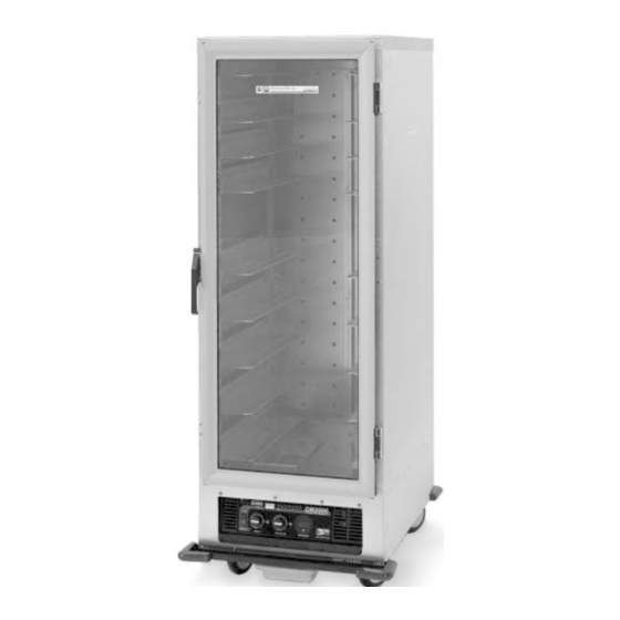
I. INTRODUCTION Your C175 series cabinet has a full-view polycarbonate door which allows unobstructed A. IDENTIFYING YOUR CABINET viewing of the cabinet contents. To prevent shipping Your cabinet assembly has been shipped in damage to the clear panel, the protective paper two cartons. -
Page 4: Features
B. FEATURES — ALL MODELS B. SLIDE RACK ASSEMBLIES In order to utilize your new cabinet to its full potential, All three models of slide racks, C4SC, C8SN, take a minute to identify the following features which CVSN are removable for thorough have been provided for your convenience. -
Page 5: Holding Module
C8SN — Model 8 (1 " Spacing-fixed) HOLDING MODULE The Model 8 Slide Rack can only be installed in the For Recommended Holding Temperatures, inboard hanger position. All pans are to be lip loaded. see HM2000 guidelines on page 7. The following pans may be used: 35 pans —... -
Page 6: Combo Module
It is not necessary at the end of the operating setting 10 and TEMPERATURE thermostat to day to disrupt the TEMPERATURE setting in setting 2. Given a normal room temperature of order to turn the unit OFF. By switching the 72°F, a PREHEAT TIME OF APPROXIMATELY POWER switch to OFF, the unit is no longer 30 MINUTES is required before proofing can... -
Page 7: Proofer Module
average temperature (72°F), this should 4. For products that will proof in 30-45 minutes at provide 150°-170°F. Adjustments to the approximately 95°F and 95% relative humidity, temperature may be made as necessary. turn the HUMIDITY thermostat to setting 10 and TEMPERATURE thermostat to setting 2. THIS IS A HOT FOOD HOLDING CABINET Given a normal room temperature of 72°F, a AND IS NOT INTENDED TO RETHERMALIZE... -
Page 8: Cm2000/Hm2000 Recommended
III. FOOD HOLDING GUIDELINES A. CM2000/HM2000 Recommended Food Holding Guidelines Temperature Setting °F* Food Product Covered/Uncovered Baked Fish Uncovered Baked Potatoes Uncovered Biscuit Uncovered Broccoli Covered 170-175 Chicken Nuggets Uncovered Corn on the Cob Covered 170-175 Croissants Uncovered Egg Patties Covered French Fries** Uncovered... -
Page 9: Cleaning Instructions
IV. CLEANING INSTRUCTIONS a. Isopropyl (rubbing) alcohol, used as a cleaner, will aid in removing grease CAUTION smudges and fingerprints. AT NO TIME SHOULD THE MODULE OR b. A small amount of liquid dish detergent in CABINET BE WASHED OR FLOODED WITH a bucket of water will help remove heavier WATER OR LIQUID SOLUTION. -
Page 10: Maintenance
V. MAINTENANCE A. CABINET MAINTENANCE — ALL MODELS Your C175 series cabinet has been designed to require very little maintenance. With normal use, cleaning is the only form of maintenance that need be done on a regular basis. Keeping the casters free of dirt build- up will go a long way in prolonging their life. -
Page 11: Replacement Parts And Procedures
VI. REPLACEMENT PARTS AND PROCEDURES A. CABINET — ALL MODELS Refer to the Cabinet Replacement Parts Diagram on next page to identify the replacement parts. C175 Series Cabinet Replacement Parts Diagram... - Page 12 VI. REPLACEMENT PARTS LIST height cabinet parts not shown) Item No. Part No. Description RPC175P-1106 Door (full height cabinet) RPC175TP-1106 Door ( height cabinet) RPC06-812 Gasket (full height cabinet) RPC06-813 Gasket ( height cabinet) RPC14-118 Door Latch — Strike Plates Included RPC14-119 Door Hinge —...
-
Page 13: Modules
MODULES — ALL MODULES c. Remove the water pan and drain water from pan. Your module has been designed to be user- serviceable, assuming a basic knowledge of d. Unfasten the electrical cover by removing the the operation of electrical devices. This section three screws along the front of the module has been written to guide the user step by step, and the two screws along each edge of the... - Page 14 Holding Module Replacement Parts Diagram REPLACEMENT PARTS LIST Item No. Part No. Description RPC13-099 Power Cord — 20 AMP RPC13-098 Strain Relief — 20 AMP RPC06-313 Thermostat Knob RPHM20-PAN Water Pan RPC13-127 Power Switch RPC13-129 Temperature Thermostat RPC13-105 Yellow Indicator Light RPHM20-2103 Circulating Blower RPC13-012...
- Page 15 Combo Module Replacement Parts Diagram REPLACEMENT PARTS LIST Item No. Part No. Description RPC13-099 Power Cord — 20 AMP RPC13-098 Strain Relief — 20 AMP RPC06-313 Thermostat Knob RPCM20-PAN Water Pan RPC13-127 Power Switch RPC13-129 Temperature Thermostat RPC13-105 Yellow Indicator Light RPHM20-2103 Circulating Blower RPC13-162...
- Page 16 Proofer Module Replacement Parts Diagram REPLACEMENT PARTS LIST Item No. Part No. Description RPC13-017 Power Cord — 15 AMP RPC13-083 Strain Relief — 15 AMP RPC06-313 Thermostat Knob RPCM20-PAN Water Pan RPC13-127 Power Switch RPC13-129 Temperature Thermostat RPC13-105 Yellow Indicator Light RPHM20-2103 Circulating Blower RPC13-162...
-
Page 17: Holding
VII. WIRING SCHEMATICS REFER TO APPROPRIATE MODULE HOLDING MODULE WIRING DIAGRAM NOTE: Wiring diagrams are shown with module upside down for servicing. -
Page 18: Combo
COMBO MODULE WIRING DIAGRAM NOTE: Wiring diagrams are shown with module upside down for servicing. -
Page 19: Proofer
PROOFER MODULE WIRING DIAGRAM NOTE: Wiring diagrams are shown with module upside down for servicing. - Page 20 Thank you for purchasing a Metro Mobile Heated Cabinet. We are certain you will be more than satisfied with its quality and performance. Please fill in the warranty information space below so we may register your warranty. Also, so that we may learn more about our customers and hopefully be of continued service in the future, please take a moment to fill in the customer information space below.
- Page 21 STAPLE HERE...
- Page 22 Warranty WARRANTY, EXCLUSION OF WARRANTIES AND LIMITATION OF LIABILITY. InterMetro Industries Corporation (hereinafter referred to as “Seller”) warrants to the original purchaser that all products in its catalog, or custom products, delivered hereunder will be free from defects in workmanship and material. THE FOREGOING WARRANTY IS EXCLUSIVE AND IN LIEU OF ALL OTHER WARRANTIES, EXPRESS, IMPLIED OR STATUTORY, INCLUDING ANY WARRANTY OF MERCHANTABILITY OR FITNESS FOR A PARTICULAR PURPOSE.
- Page 23 L01-385 InterMetro Industries Corporation Rev. A 03 ® North Washington Street, Wilkes-Barre, PA 18705 Information and specifications are subject to change without notice. Please confirm at time of order. For Product Information Call: 1-800-433-2232 Visit Our Web Site: www.metro.com...
Need help?
Do you have a question about the C175 Series and is the answer not in the manual?
Questions and answers