Table of Contents
Advertisement
Operator's Manual
Operator's Manual
MercuryiTC
Oxford Instruments Omicron
Oxford Instruments
NanoScience
NanoScience
MercuryiTC
Cryogenic environment controller
Cryogenic environment controller
Issue 05
/
Feb 2015
©2014 Oxford Instruments Omicron NanoScience
/
Original Instructions
Original Instructions
Omicron NanoScience. All rights reserved.
Issue 05
/
Feb 2015 / UMC0071
Feb 2015 / UMC0071
Omicron
Advertisement
Table of Contents
Troubleshooting

Summary of Contents for Oxford Instruments Omicron NanoScience MercuryiTC
- Page 1 Feb 2015 / UMC0071 Feb 2015 / UMC0071 MercuryiTC Oxford Instruments Oxford Instruments Omicron Omicron NanoScience NanoScience MercuryiTC Cryogenic environment controller Cryogenic environment controller Issue 05 Feb 2015 Original Instructions Original Instructions ©2014 Oxford Instruments Omicron NanoScience Omicron NanoScience. All rights reserved.
-
Page 2: Table Of Contents
1.2.3 Acoustic noise caution ......................11 Solid waste ........................12 Mercury iTC BASICS ......................13 MercuryiTC front and rear panels ................. 14 Display and touch-screen ..................... 15 Electrical power supply ....................15 Temperature sensor circuits ..................15 Heater circuits ......................15 Optional cooling circuit control .................. - Page 3 GETTING STARTED ......................23 Checking the electrical supply ..................23 Mounting the equipment ....................23 Connecting electrical power..................24 Powering up the MercuryiTC for the first time ............... 24 The MercuryiTC touch screen ..................25 3.5.1 The home page ........................26 3.5.2...
- Page 4 Calibration for different sensors .................... 62 4.11.7 Available generic calibration files ..................64 4.12 More about thermocouples ..................65 4.12.1 Thermocouple principles ....................... 65 4.12.2 Configuring for thermocouples ....................65 4.12.3 Reference junction compensation ..................67 ©2014 Oxford Instruments Omicron NanoScience. All rights reserved.
- Page 5 5.2.3 Basic check of board operation..................... 74 Connecting the level probe ................... 74 Configuring MercuryiTC for helium level meter ............. 74 Configuring MercuryiTC for nitrogen level meter ............76 Setting up liquid nitrogen auto-fill .................. 78 MANAGING YOUR MERCURY ..................80 General ........................
- Page 6 Configuring USB ......................... 100 7.4.2 USB Cabling requirements ....................100 7.4.3 USB drivers ......................... 100 Switching MercuryiTC control between local and remote ..........100 Testing remote connections..................101 Programming examples ....................101 COMMAND REFERENCE GUIDE ..................102 Nomenclature used in this section ................102 SCPI and legacy command sets ..................102 SCPI commands ......................102...
- Page 7 Configuring an output on the auxiliary I/O board ..............132 PRESSURE BOARD....................134 12.1 Description of the pressure board ................134 12.1.1 Description of the pressure board circuit ................134 12.2 Installing a pressure board ..................137 12.2.1 Fitting the board ........................137 ©2014 Oxford Instruments Omicron NanoScience. All rights reserved.
- Page 8 Automatic control of the gas flow ..................151 14.3.4 Heater target tables ......................152 14.3.5 Siphon algorithm ......................... 152 PREVENTIVE MAINTENANCE ..................153 15.1 Cleaning the touch-screen ..................153 15.2 Calibrating the temperature sensor circuits ..............153 15.3 Lubricating the fan ....................153 ©2014 Oxford Instruments Omicron NanoScience. All rights reserved.
- Page 9 17.3 Sensor inputs ......................161 17.4 Heater outputs ......................162 17.5 PC interfaces ......................162 17.6 Electrical isolation ....................163 17.7 Environmental specifications ...................163 17.8 Level meter board ....................163 17.9 Pressure board ......................164 CUSTOMER SUPPORT ....................165 ©2014 Oxford Instruments Omicron NanoScience. All rights reserved.
-
Page 10: Preface
The MercuryiTC is intended to be installed, used and operated only for the purpose for which the MercuryiTC was designed, and only in accordance with the instructions given in this manual and other accompanying documents. - Page 11 Revision history This is issue 03 of the MercuryiTC Handbook, as shown in the header at the top of each page. The changes made to this document and a summary of previous issues are listed in the table below.
-
Page 12: Customer Support
MercuryiTC Customer support Oxford Instruments Omicron NanoScience has global customer support facilities that provide a coordinated response to customer’s queries. All queries are recorded on our support database and are dealt with as quickly as possible. If we are not able to answer the query immediately, we will contact you promptly. -
Page 13: Health And Safety Information
MercuryiTC Health and safety information The MercuryiTC contains hazardous areas. Before working with the iTC, all personnel must read and become thoroughly familiar with the information given in chapter 1. In particular, users must read, understand and strictly observe all: •... -
Page 14: Disclaimers
Feb 2015 / UMC0071 MercuryiTC Disclaimers Oxford Instruments Omicron NanoScience assumes no liability for use of this document if any unauthorised changes to the content or format have been made. The policy of Oxford Instruments Omicron NanoScience is one of continued improvement. The Company reserves the right to alter without notice the specification, design or conditions of supply of any of its products or services. -
Page 15: Acronyms
Pulse Width Modulation Room Temperature SCPI Standard Commands for Programmable Instruments (a command protocol) Serial Peripheral Interface To be advised Thin film transistor Unique Identifier Universal Serial Bus Variable Temperature Insert Page 6 ©2014 Oxford Instruments Omicron NanoScience. All rights reserved. -
Page 16: Certification Compliance Statements
Operator's Manual Issue 05 Feb 2015 / UMC0071 MercuryiTC Certification compliance statements The MercuryiTC cryogenic environment controller has been tested to the following standards and certifications: • CE • IEC61010-1: 2010 3 edition: Safety requirements for electrical equipment for measurement, control and laboratory use. -
Page 17: About Oxford Instruments
Oxford Instruments Omicron NanoScience Limited Oxford Instruments Omicron NanoScience creates high performance environments for low temperature and high magnetic field applications in physical science research and process development down to the atomic scale. -
Page 18: Health And Safety
Do not connect external electrical circuits to the equipment if its protective ground is disconnected. There is a ground pillar on the rear panel, identified by a symbol. Connect the grounds of any external equipment to this pillar. Page 9 ©2014 Oxford Instruments Omicron NanoScience. All rights reserved. -
Page 19: High Voltage Hazard
The equipment is not suitable for use in explosive, flammable or hazardous environments. The equipment does not provide protection against the ingress of water. The equipment must be positioned so that it will not be exposed to water ingress. Page 10 ©2014 Oxford Instruments Omicron NanoScience. All rights reserved. -
Page 20: Cautions
EQUIPMENT VENTILATION If the MercuryiTC is to be rack mounted, to ensure an adequate airflow around the iTC, it is important that the back of the rack is open and the rack is not placed less than 30 cm from a back wall. -
Page 21: Solid Waste
1.3 Solid waste The lithium battery on the motherboard will become solid waste if it has to be replaced. Dispose of this item according to local and national regulations. Page 12 ©2014 Oxford Instruments Omicron NanoScience. All rights reserved. -
Page 22: Mercury Itc Basics
The iTC can be configured to control the application of heat to a cooling medium, as this method provides better control than adjusting the refrigeration process. The MercuryiTC can also control sample cooling by fitting an auxiliary I/O board, which can control the flow of gas in a continuous-flow cryostat. -
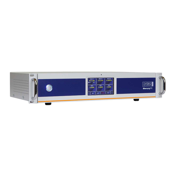
Page 23: Mercuryitc Front And Rear Panels
The On/Off button illuminates blue when the iTC is powered up. Figure 2 shows the rear panel of a MercuryiTC. This photo will not look exactly like your iTC as it depends on the number and type of boards fitted. -
Page 24: Display And Touch-Screen
MercuryiTC 2.2 Display and touch-screen The MercuryiTC contains a 4.3 inch full-colour liquid crystal display (LCD) with a touch-screen. The touch screen is the main input device to the iTC. The front panel is also fitted with an ambient-light sensor. The iTC can be configured to change the display brightness automatically to match ambient light conditions. -
Page 25: Optional Cooling Circuit Control
This results in faster response time, more accuracy, and removes synchronization issues, since the reading is absolute. Now, only mechanical faults will result in losing track of the motor position. Page 16 ©2014 Oxford Instruments Omicron NanoScience. All rights reserved. -
Page 26: Remote Interfaces
The slave connectors draw electrical power from the individual instruments, via the DCD signal. The master connector draws electrical power from either the DTR or RTS signals from the computer. A special command protocol is required to use ISOBUS (see section 8.4.1). Page 17 ©2014 Oxford Instruments Omicron NanoScience. All rights reserved. -
Page 27: Functional Description
Operator's Manual Issue 05 Feb 2015 / UMC0071 MercuryiTC 2.8 Functional Description A block diagram of the MercuryiTC is given below. Page 18 ©2014 Oxford Instruments Omicron NanoScience. All rights reserved. -
Page 28: Main Components
Feb 2015 / UMC0071 MercuryiTC 2.9 Main components This section gives a brief description of the internal components of the MercuryiTC. Figure 3 shows how these components are arranged inside the MercuryiTC enclosure. Figure 3 View of internal layout of MercuryiTC The MercuryiTC consists of: •... -
Page 29: Motherboard
(e.g. a PC). Only one of these boards can be fitted. Chapter 13 gives a full technical description. • Pressure This is a board which measures signals from a pressure transducer. It can be used to control Page 20 ©2014 Oxford Instruments Omicron NanoScience. All rights reserved. - Page 30 A maximum of eight of these boards can be fitted. Chapter 12 gives a full technical description. The iTC automatically identifies every daughter board present. Figure 4 Layout of MercuryiTC expansion slots The location of daughter boards is subject to certain constraints, as given in the following table. Board...
-
Page 31: Alarms And Interlocks
Configuration is described in section.4.5. 2.10 Alarms and interlocks The MercuryiTC is designed to identify common faults, such as wiring errors that produce open-circuit or short-circuit conditions. For errors that require immediate user intervention, the MercuryiTC sounds a 1kHz buzzer. The buzzer sounds intermittently, with the repetition rate increasing for more serious errors. -
Page 32: Getting Started
Exploiter l'équipement avec une tension incorrecte peut l'endommager de manière permanente. The MercuryiTC automatically configures itself to match the supplied electrical power supply. If the voltage and frequency are within the specified ranges (see section 17.2), no user intervention is required. -
Page 33: Connecting Electrical Power
The back panel contains an IEC C14 connector for the main electrical supply to the MercuryiTC. Section 17.2 gives mains electrical requirements. 3.4 Powering up the MercuryiTC for the first time Operate the switch on the rear panel of the Mercury so that the 1 is depressed. -
Page 34: The Mercuryitc Touch Screen
Issue 05 Feb 2015 / UMC0071 MercuryiTC Press the Power button on the left of the front panel. The button illuminates blue. The MercuryiTC initialises, then the Home page appears on the touch screen. widget button • This screenshot shows the default home page. A different home page will appear if Oxford Instruments has pre-configured the iTC for your system. -
Page 35: The Home Page
• Plot button. Tap once to plot information against time (see section 3.6). • Control button. Tap once to display control-loop information. Heater power (section 4.5) and gas flow (section 4.9) can be controlled. Page 26 ©2014 Oxford Instruments Omicron NanoScience. All rights reserved. -
Page 36: Custom Home
• Identifier of the channel heater (if applicable). • Output power of the channel heater (if applicable). • Identifier of the gas-flow controller (if applicable). • Percentage flow for the gas-flow controller (if applicable). Page 27 ©2014 Oxford Instruments Omicron NanoScience. All rights reserved. -
Page 37: Drop-Down Menus
On some pages there is not enough space to display all the keys or information associated with the page. This is indicated by a button with the label Tap the button to scroll to the left. Tap the button to scroll to the right. Page 28 ©2014 Oxford Instruments Omicron NanoScience. All rights reserved. -
Page 38: Soft Keypads
Del or tap the new digits. • Tap OK to save the number entered. • Tap Quit to close the keypad without saving the number that has been entered. CAPS is not used. Page 29 ©2014 Oxford Instruments Omicron NanoScience. All rights reserved. - Page 39 • Tap a key twice to enter the first character displayed on the key. • Tap a key three, four, or five times to enter subsequent characters displayed on the key. Page 30 ©2014 Oxford Instruments Omicron NanoScience. All rights reserved.
-
Page 40: Using Arrows To Adjust Integer Values
Some buttons operate differently to the method just described. The operation of these buttons is described in the text. 3.5.9 Common touch screen features The following buttons appear on several pages of the GUI. • Tap once to return to the Home page. Page 31 ©2014 Oxford Instruments Omicron NanoScience. All rights reserved. -
Page 41: Setting The Date And Time
This process is a simple example showing how the touch screen is used. Tap Settings on the Home page. This displays the first of several Settings pages. Scroll the tabs using until the Clock tab is displayed. Page 32 ©2014 Oxford Instruments Omicron NanoScience. All rights reserved. -
Page 42: Plotting Signals On The Mercuryitc Touch Screen
Tap Home to return to the Home page. 3.6 Plotting signals on the MercuryiTC touch screen The MercuryiTC touch screen allows the user to monitor up to 6 signals as a function of time. 3.6.1 Plot Configuration The Plot Configuration page is used to set up which signals are to be plotted. When the plot page has been configured, the trace updates in real time. - Page 43 Selected Signals. Repeat to add more signals. Use the button to remove a signal. Use the buttons to move a selected signal up or down the list. Tap OK to open the plot. Page 34 ©2014 Oxford Instruments Omicron NanoScience. All rights reserved.
-
Page 44: Scaling A Plot
X-axis and contracts the Y-axis. These instructions are summarised in the following diagram. Double tap on a scale to return to the default scaling for that axis. Page 35 ©2014 Oxford Instruments Omicron NanoScience. All rights reserved. - Page 45 Operator's Manual Issue 05 Feb 2015 / UMC0071 MercuryiTC Page 36 ©2014 Oxford Instruments Omicron NanoScience. All rights reserved.
-
Page 46: How To Measure And Control Temperature
• Cabling requirements • Configuring the temperature sensor • Configuring the heater • Configuring the heater control loop • PID control and PID tables • Configuring the gas control loop (optional) Page 37 ©2014 Oxford Instruments Omicron NanoScience. All rights reserved. -
Page 47: Heater And Sensor Connections
This is achieved by connecting together pins 3, 4 and 5 of the 9 way D connector (see table above). Biasing the thermocouple in this way prevents error currents flowing in the Page 38 ©2014 Oxford Instruments Omicron NanoScience. All rights reserved. -
Page 48: Configuring A Temperature Sensor
Tap once on an unconfigured widget. The Channel Display Configuration page is displayed. Tap the Device parameter box and choose a temperature sensor input from the drop-down list. This will be labelled ***.T1 (DB6.T1 in the example below). Then tap OK. Page 39 ©2014 Oxford Instruments Omicron NanoScience. All rights reserved. -
Page 49: Configuring The Sensor Details
The list of Sensor Readings depends on the type of sensor but will generally include I (µA) - the sensor excitation current in µA. P (µW) - the power dissipated in the sensor in µW. Page 40 ©2014 Oxford Instruments Omicron NanoScience. All rights reserved. - Page 50 Tap once to access the Generic Sensor Adjustment page (see section 4.10.2). This allows the user to adjust the scale and offset of a generic calibration curve to suit a particular sensor. Page 41 ©2014 Oxford Instruments Omicron NanoScience. All rights reserved.
-
Page 51: To Clear A Widget Configuration
Double-tap the widget on the Home page. Tap the Device parameter box and select None from the drop-down menu. Tap Assign. The widget on the Home page should now display the name None. Page 42 ©2014 Oxford Instruments Omicron NanoScience. All rights reserved. -
Page 52: Setting Heater Properties
4.3 Setting heater properties This page displays a set of values for every configured heater, in particular voltage limits for individual heaters. If your MercuryiTC is supplied as part of a system, this page will be set up already. Tap Heater on the Home page to view the heater properties page. -
Page 53: Configuring A Heater
A temperature sensor is normally paired with a heater. The page contains a table with 7 columns. You must scroll to the right to see them all. The appearance of the page with no configured pairings is shown below. Page 44 ©2014 Oxford Instruments Omicron NanoScience. All rights reserved. - Page 54 This is an additional safety feature, normally set to the end of the calibration range. An external input from the auxiliary I/O card (if fitted) cuts off the heater if the sensor reaches the indicated temperature. Tap Home to return to the Home page. Page 45 ©2014 Oxford Instruments Omicron NanoScience. All rights reserved.
-
Page 55: Configuring The Heater Control Loop
4.5.2 Configuring automatic heater control The MercuryiTC uses a PID table to control the heater. For a detailed description of the principles involved, please consult chapter 14. If you selected Auto control, tap PID and select either Manual or Auto PID operation. Auto PID means that the PID values for the control loop are automatically loaded from a PID table. - Page 56 Tap P to enter the width of the proportional band. Tap I and D, respectively, to enter values for the integral and differential parameters. Alternatively, tap Load, select a file from the list, then tap Load again, to load an existing PID table. Page 47 ©2014 Oxford Instruments Omicron NanoScience. All rights reserved.
-
Page 57: Changing A Temperature Set Point In Automatic Control
Tap the Set Point button until it displays Fixed. Tap the set point parameter box to open a numeric window. Enter the new set point. Tap Home to return to the Home page. Page 48 ©2014 Oxford Instruments Omicron NanoScience. All rights reserved. -
Page 58: Using The Sweep Function
Tap Control on the Home page. The Control Loop Configuration page is displayed. Select the required temperature sensor from the list in the Sensor parameter box. Tap Heat(%) to read Auto. Page 49 ©2014 Oxford Instruments Omicron NanoScience. All rights reserved. - Page 59 Enter the time to hold the step temperature (in minutes) in the Hold At Final T(mins) parameter box in row 1. to add another row to the table and repeat steps 6 – 8. Page 50 ©2014 Oxford Instruments Omicron NanoScience. All rights reserved.
-
Page 60: Loading A Sweep
Select the required temperature sensor from the list in the Sensor parameter box. Tap the Set point button until it displays Sweep . The Set point parameter box value will change as the sweep proceeds. Page 51 ©2014 Oxford Instruments Omicron NanoScience. All rights reserved. -
Page 61: Stopping A Sweep
This command sets the ramp rate to 5.25K/min for the control loop controlled by the MB1 temperature sensor input. The system returns STAT:SET:DEV:MB1.T1:TEMP:LOOP:RSET:VALID Send a remote command to read the temperature READ:DEV:MB1.T1:TEMP:SIG:TEMP The system returns STAT:DEV:MB1.T1:TEMP:SIG:TEMP:xxx.xxxxK where xxx.xxxx is the value of the temperature. Page 52 ©2014 Oxford Instruments Omicron NanoScience. All rights reserved. -
Page 62: Starting A Ramp
MB1 temperature sensor input. This will start the loop set point ramping at the ramp rate previously set. STAT:SET:DEV:MB1.T1:TEMP:LOOP:TSET:VALID 4.8.4 To disable ramp mode To disable ramp mode, send a remote command such as: SET:DEV:MB1.T1:TEMP:LOOP:RENA:OFF Page 53 ©2014 Oxford Instruments Omicron NanoScience. All rights reserved. -
Page 63: Configuring A Gas Valve
In the row for the desired sensor, tap the cell in the Flow column. Select the gas controller from the drop-down menu (not shown). Tap OK to save the configuration. The example below shows a gas controller in daughter board number 4. Page 54 ©2014 Oxford Instruments Omicron NanoScience. All rights reserved. - Page 64 Tap the Flow(%) button to select either Manual or Auto Control. Manual configures the gas controller for open-loop control (see section 4.9.1). Auto configures the gas controller and associated temperature sensor in a closed control loop (see section 4.9.2). Page 55 ©2014 Oxford Instruments Omicron NanoScience. All rights reserved.
-
Page 65: Configuring Manual Control Of The Gas Valve
If Auto is selected in the Flow(%) parameter box, tap Gas Cfg. The Gas Flow Configuration page opens, as above. Tap HTT and select a Heater Target Table (file) from the drop-down list to be used for controlling the valve. Page 56 ©2014 Oxford Instruments Omicron NanoScience. All rights reserved. - Page 66 See section 14.3. Tap Type and select either Siphon or VTI depending which type of flow system you are using. See also section 14.3. Tap Home to return to the Home page. Page 57 ©2014 Oxford Instruments Omicron NanoScience. All rights reserved.
-
Page 67: Changing A Gas Flow Set Point
(ideally near the high-resistance end of the range). If a scale adjustment of more than a few percent is required to correct the temperature reading, investigate the measurement set-up to check there is not some other error present. Page 58 ©2014 Oxford Instruments Omicron NanoScience. All rights reserved. -
Page 68: Adjusting A Generic Calibration File
Tap Calibration and from the drop-down list select the generic file corresponding to the sensor. This example selects RP51.dat for a PT100. Tap Cal Adj to open the Generic Sensor Adjustment page. Page 59 ©2014 Oxford Instruments Omicron NanoScience. All rights reserved. -
Page 69: Types Of Temperature Sensor
4.11 Types of temperature sensor The MercuryiTC can use several types of temperature sensor. 4.11.1 Thermocouples A thermocouple comprises two junctions of dissimilar metals held at different temperatures. This acts as a voltage source, based on the Seebeck effect, the output voltage of which increases Page 60... -
Page 70: Metallic Resistance Thermometers (Positive Temperature Coefficient)
Resolution to 1mK is possible at low temperatures. 4.11.5 Excitation current Resistance and diode sensors require an excitation current. A 4-wire connection is used for these sensors. Page 61 ©2014 Oxford Instruments Omicron NanoScience. All rights reserved. -
Page 71: Calibration For Different Sensors
Calibration tables can be saved as files. The MercuryiTC accepts calibration files with .dat or .prn extensions. • A calibration file contains a number of discrete data pairs, each mapping a sensor reading on to a temperature value. - Page 72 • There is no theoretical limit to the number of sets of data points, but a practical limit is about 1000. The iTC calculates set point limits and sensor limits from the chosen calibration file. Page 63 ©2014 Oxford Instruments Omicron NanoScience. All rights reserved.
-
Page 73: Available Generic Calibration Files
470R Speer 0.25 to 9.999K Your MercuryiTC may not have all the above calibration files pre-loaded. The Lin and Null ranges are general purpose ranges that may be configured for any required span and zero. Both ranges provide a linear relationship between input and display. The Lin range is unipolar while the Null range is bipolar. -
Page 74: More About Thermocouples
For these reasons, a resistance thermometer normally provides better performance, especially at low temperature. 4.12.2 Configuring for thermocouples The Home page below shows a MercuryiTC configured for a Au-Fe/chromel thermocouple with a liquid nitrogen reference. The widgets have been configured as follows: Page 65... - Page 75 Where a calibration file with a “Merc” prefix is available, such as MercTG57-2.dat, then this is preferred. Such files have a higher data point density than those used in the previous generation of Oxford Instruments temperature controllers (eg. TG57-2.dat). See also section 4.11.7. Page 66 ©2014 Oxford Instruments Omicron NanoScience. All rights reserved.
-
Page 76: Reference Junction Compensation
MercuryiTC 4.12.3 Reference junction compensation The MercuryiTC configuration options permit an internal or external reference junction to be used. Each iTC temperature sensor circuit has a built-in temperature reference chip (ADT7310) adjacent to the 9 way D-connector. The real-time temperature reported by this chip is used to compensate the thermocouple voltage measurement. -
Page 77: Heater Control Interlock
The MercuryiTC assumes that the temperature of the reference junction is fixed so the voltage reduction is interpreted as a reduction of the temperature of the measurement junction. - Page 78 Feb 2015 / UMC0071 MercuryiTC The MercuryiTC auxiliary I/O daughter board is used to detect if the voltage from the semiconductor device (typically 1.8V) is exceeded, which it will if the device warms above about 85K. This switches the state of the digital signal on input line 2 of the auxiliary I/O board which is then used as an interlock for the heater.
-
Page 79: Cryogen Level-Meter
Do not perform measurements too often, as each Page 70 ©2014 Oxford Instruments Omicron NanoScience. All rights reserved. -
Page 80: Operation Of The Board With A Nitrogen-Level Probe
Turn off electrical power to the iTC. Disconnect all cables from the rear of the iTC and remove the iTC from any instrument rack. Remove the 4 screws holding each rack handle. Page 71 ©2014 Oxford Instruments Omicron NanoScience. All rights reserved. -
Page 81: Fitting The Board
5.2.2 Fitting the board The level-meter board can be fitted in any expansion slot. Only one level meter board can be fitted in a MercuryiTC, because of power consumption limitations. Choose a slot for the level meter board. Remove the two screws that secure the top clamping bracket (Figure 5). Remove the board clamp. - Page 82 Issue 05 Feb 2015 / UMC0071 MercuryiTC Figure 6 MercuryiTC daughter board blanking plate Using appropriate ESSD precautions, including wearing an anti-static wrist strap, fit the board in the allocated expansion slot. Align the board with the appropriate slot. Slide the board faceplate inside the iTC back plane.
-
Page 83: Basic Check Of Board Operation
Replace the top cover on to the iTC, reversing the procedure for removal. 5.2.3 Basic check of board operation Power up the MercuryiTC. If fitted correctly, the iTC will detect the board and may request permission to use it. Put the iTC in Local mode by tapping the local/remote toggle button on the iTC Home page. - Page 84 11 Enter a value in seconds in the Measurement Pulse Duration (s) parameter box. 3s is a suitable value. 12 Tap the Fast/Slow button to display Fast. The example page below shows typical values for all parameters. Page 75 ©2014 Oxford Instruments Omicron NanoScience. All rights reserved.
-
Page 85: Configuring Mercuryitc For Nitrogen Level Meter
16 Tap Assign to save the changes and return to the Home page. The level meter widget now reads the helium level (%). 5.5 Configuring MercuryiTC for nitrogen level meter Tap an unconfigured widget on the Home page to display the Channel Display Configuration page. - Page 86 11 Fit the probe to the system and fill it with liquid nitrogen. Wait for the boiling to subside. Record the pulse count reading and use this for Frequency at 100% value. Page 77 ©2014 Oxford Instruments Omicron NanoScience. All rights reserved.
-
Page 87: Setting Up Liquid Nitrogen Auto-Fill
An example is shown above. Enter a percentage value for the required Low Level (typically 10%). The auto-fill valve opens when the level falls below the Low Level value. Page 78 ©2014 Oxford Instruments Omicron NanoScience. All rights reserved. - Page 88 Enter a percentage value for the required High Level (typically 90%). The auto-fill valve closes when the level rises above the High Level value. Tap Home to return to the Home page. Page 79 ©2014 Oxford Instruments Omicron NanoScience. All rights reserved.
-
Page 89: Managing Your Mercury
6 MANAGING YOUR MERCURY This chapter describes • general operation of the MercuryiTC, and how this can be configured to suit the user. • how to manage software updates • how to Save and Load files, such as PID and calibration files. - Page 90 Tap once to apply (save) changes made on this page. • Home Tap once to return to the Home page. The General page also displays the firmware version in use. Page 81 ©2014 Oxford Instruments Omicron NanoScience. All rights reserved.
-
Page 91: Display
(%) must be less than, or equal to, Brightness (%). • Style There are two choices for the display colours. oi is the name of the default textured blue style. Page 82 ©2014 Oxford Instruments Omicron NanoScience. All rights reserved. - Page 92 Tap once to access the Alarm Logs page (see section 16.1.1). If the text is RED an alarm condition exists. • Apply Tap once to apply (save) changes made on this page. • Home Tap once to return to the Home page. Page 83 ©2014 Oxford Instruments Omicron NanoScience. All rights reserved.
-
Page 93: Devices
The name (or user-defined nickname) of the device associated with the board fitted in this slot. • Serial No The serial number of the board fitted in this slot. • Board Rev. The revision number of the board. Page 84 ©2014 Oxford Instruments Omicron NanoScience. All rights reserved. -
Page 94: Clock
Tap once to return to the Home page. Tap once in any row to switch to the appropriate configuration page for the device. 6.4 Clock Select the Clock tab to reset the MercuryiTC internal clock. The page contains the following parameter boxes and controls: • Time Tap the part of the displayed time that you wish to edit and use the buttons. -
Page 95: File Transfer
Select the type of calibration file to be loaded. The list of file types comprises: Diode, Dummy, NTC, PTC, Thermocouple, HTT, Pressure, sweep_tables, pid_tables. • File Select the file to be loaded from the memory stick. Once selected, the file is loaded automatically. Page 86 ©2014 Oxford Instruments Omicron NanoScience. All rights reserved. -
Page 96: Updates
Users are able to take advantage of software developments without the need to return the MercuryiTC to the factory. The terminology used is as follows. The Mercury application is software that runs on the MercuryiTC and allows the user to interact with the instrument using the touch screen GUI. It translates and communicates user commands to the appropriate device (board). - Page 97 The iTC installs the new firmware and calibrates the heater board(s) and pressure board (if fitted). It then re-boots and starts up in TRIAL mode. Do not power-off the iTC in TRIAL mode! Page 88 ©2014 Oxford Instruments Omicron NanoScience. All rights reserved.
-
Page 98: Access Level
The user can change this password, if desired (see below). Entering engineering mode Tap Settings on the Home page. Scroll right until the Access Level tab is visible. Tap Access Level. The engineering mode page opens. Page 89 ©2014 Oxford Instruments Omicron NanoScience. All rights reserved. - Page 99 Tap Access Level. The engineering mode page opens with the message “Engineering mode is enabled”, as shown above. Tap Exit Mode. The iTC is no longer in engineering mode. The previous page reappears with the prompt for password. Page 90 ©2014 Oxford Instruments Omicron NanoScience. All rights reserved.
-
Page 100: Factory
Feb 2015 / UMC0071 MercuryiTC 6.8 Factory This page allows the user to save the configuration of the MercuryiTC. The user can then restore a previously saved configuration. The page contains the following parameter boxes and controls: • Save configuration To save the present system configuration, enter a filename in the Enter Name parameter box and tap Save Configuration. -
Page 101: Load File
There is a Load button on several pages. All function in the same way, so only one is described in this section. This page (below) appears when editing a PID file. Page 92 ©2014 Oxford Instruments Omicron NanoScience. All rights reserved. - Page 102 Tap once and enter the required filename, without a file extension. • Load Tap once to load the selected file. • Delete Tap once to delete a selected file. • Cancel Tap once to exit without loading the file. Page 93 ©2014 Oxford Instruments Omicron NanoScience. All rights reserved.
-
Page 103: Remote Operation
Dans cette opération ne doit pas se produire au-dessus d'un niveau d'humidité de 91% à 20 ° C. The MercuryiTC can be remotely operated using any of the following interfaces: • RS232 or ISOBUS • GPIB (IEEE-488) •... - Page 104 Select a flow-control scheme for the RS232 interface from the drop-down menu. The page also contains the following buttons: • Alarm Tap once to access the Alarm Logs page (see section 16.1). If the text is RED an alarm condition exists. Page 95 ©2014 Oxford Instruments Omicron NanoScience. All rights reserved.
-
Page 105: Serial Rs232 Cabling Requirements
Voltage levels for the transmitted and received data are as follows. Signal Allowed voltage Tx data high >+5.5 V Tx data low <-5.5 V Rx data high threshold <+2.6 V Rx data low threshold >+1.4 V Page 96 ©2014 Oxford Instruments Omicron NanoScience. All rights reserved. -
Page 106: Remote Operation Using Gpib
SCPI commands via GPIB. If the Legacy command set is being used the “Secondary Address” is not invoked and therefore is not required. The page also contains the following buttons: Page 97 ©2014 Oxford Instruments Omicron NanoScience. All rights reserved. -
Page 107: Gpib Cabling Requirements
Connect the iTC to the bus using a standard GPIB cable. 7.3 Remote operation using Ethernet 7.3.1 Configuring Ethernet The iTC can be configured to use a fixed IP address, or to use dynamic host configuration protocol (DHCP). Page 98 ©2014 Oxford Instruments Omicron NanoScience. All rights reserved. - Page 108 • MAC Address The MAC address of the iTC is displayed. This value is assigned at the factory and cannot be edited. The page also contains the following buttons: Page 99 ©2014 Oxford Instruments Omicron NanoScience. All rights reserved.
-
Page 109: Ethernet Cabling Requirements
Since USB is a one-to-one connection, no addresses are required. 7.4.2 USB Cabling requirements The MercuryiTC rear panel is fitted with a standard USB type B receptacle. Use a standard USB A to B cable between PC and iTC. 7.4.3 USB drivers USB drivers for Windows OS are available to download from the Mercury support website www.mymercurysupport.com. -
Page 110: Testing Remote Connections
• NI LabView VIs. This is a library of Vis for National Instruments LabView version 8.6 and later. • Communication with MagLab over ISOBUS. This document is a guideline on how to establish communication between MagLab software and MercuryiTC over the serial ISOBUS interface. • Teslatron (OxSoft) Installer. This is an installation package including executable installer, source code, MercuryiTC driver and an operation manual. -
Page 111: Command Reference Guide
SCPI (Standard Commands for Programmable Instruments 1990 (IEEE 488.2)) command architecture but does not claim to fully support this architecture. Below are examples of standard SCPI commands which are NOT supported:- Page 102 ©2014 Oxford Instruments Omicron NanoScience. All rights reserved. -
Page 112: Scpi Protocols
The maximum line length is 1024 bytes (characters), including line terminators. All command lines are terminated by the new line character \n (ASCII 0x0Ah). 8.3.2 Reading the instrument identity Send the command: *IDN? (plus termination \n) Page 103 ©2014 Oxford Instruments Omicron NanoScience. All rights reserved. -
Page 113: Basic Scpi Command Structure
If responding to a SET verb, the STAT verb is followed by the value set. Examples: Send: READ:SYS:TIME (meaning ‘read system time’) Response: STAT:SYS:TIME:13:57:23 (meaning ‘status system time is 13:57:23’) Send: SET:DEV:MB1.T1:TEMP:TSET:4.321 (meaning ‘set device motherboard1, temperature1, temperature signal target value to 4.321K’) Page 104 ©2014 Oxford Instruments Omicron NanoScience. All rights reserved. -
Page 114: Nouns
The scale is of the form: n# - nano u# - micro m# - milli # - none k# - kilo M# - mega where # is replaced by the relevant SI unit. For example: Page 105 ©2014 Oxford Instruments Omicron NanoScience. All rights reserved. - Page 115 1 - 2 Sets the number of stop bits RS232 DATA 7 - 8 Sets the number of data bits RS232 none:odd:even:mark:space Sets the parity RS232 FLOW none:hardware:Xon/Xoff Sets the flow control Page 106 ©2014 Oxford Instruments Omicron NanoScience. All rights reserved.
- Page 116 To address a temperature sensor, use the following structure: DEV:<UID>:TEMP where <UID> is a unique identifier that is allocated to each board, based on its SPI location. The configuration settings for a temperature sensor are DEV:<UID>:TEMP followed by: Page 107 ©2014 Oxford Instruments Omicron NanoScience. All rights reserved.
- Page 117 The signals that are available depend on the type of sensor being addressed. If a signal is unavailable, the message INVALID is returned. Example of configuring a temperature sensor The following command configures a temperature sensor: Page 108 ©2014 Oxford Instruments Omicron NanoScience. All rights reserved.
- Page 118 LOOP PIDT OFF:ON table) Sets the file to read from for the LOOP PIDF automatic PID Table Sets the file to read from for the LOOP THTF Target Heater Table Page 109 ©2014 Oxford Instruments Omicron NanoScience. All rights reserved.
- Page 119 Indicates the maximum power of the heater Calibrates the hardware The signals for a heater controller are DEV:<UID>: HTR followed by: COMMAND OPTIONS Read/Write DESCRIPTION VOLT Heater voltage CURR Heater current POWR Heater power dissipation Page 110 ©2014 Oxford Instruments Omicron NanoScience. All rights reserved.
- Page 120 The signals for a level meter sensor are DEV:<UID>:LVL: followed by: COMMAND OPTIONS Read/Write DESCRIPTION Helium level Helium sensor resistance COUN Nitrogen sensor pulse count FREQ Nitrogen sensor measured frequency Nitrogen sensor level Page 111 ©2014 Oxford Instruments Omicron NanoScience. All rights reserved.
- Page 121 Where <UID> is a unique identifier that is allocated to each board, based on its SPI location. The configuration settings for an auxiliary board are DEV:<UID>:PRES: followed by: COMMAND OPTIONS Read/Write DESCRIPTION Reads the hardware version of the daughter HVER card Page 112 ©2014 Oxford Instruments Omicron NanoScience. All rights reserved.
- Page 122 Assign Heater device to Temperature Assign Auxiliary device to LOOP Temperature LOOP Set the P Value LOOP Set the I Value LOOP Set the D Value LOOP PIDT OFF:ON Sets automatic PID values (from Page 113 ©2014 Oxford Instruments Omicron NanoScience. All rights reserved.
-
Page 123: Invalid Responses
The commands are case-sensitive. m and n represent integers or decimal numbers. The number format is specified in the relevant section. The maximum line length is 1024 bytes (characters), including line terminators. Page 114 ©2014 Oxford Instruments Omicron NanoScience. All rights reserved. -
Page 124: Legacy Monitor Commands
Possible values for the command are listed below: Set temperature Sensor 1 temperature Sensor 2 temperature Sensor 3 temperature Temperature error (+ve when setpoint>measured) Heater output (as % of current limit) Heater output (approximate) volt Page 115 ©2014 Oxford Instruments Omicron NanoScience. All rights reserved. - Page 125 Local and locked Remote and locked Local and unlocked Remote and unlocked Sweep Status nn = 0 to 32, as follows: nn=0 Sweep not running nn=2P-1 Sweeping to step P Page 116 ©2014 Oxford Instruments Omicron NanoScience. All rights reserved.
-
Page 126: Legacy Control Commands
The value is a decimal percentage of the maximum flow, with a resolution of 0.1%. 8.4.3.4 Hn command - Set Heater Sensor The HEATER SENSOR command specifies the sensor to be used for automatic control: Page 117 ©2014 Oxford Instruments Omicron NanoScience. All rights reserved. -
Page 127: Legacy System Commands
(which depends on the configuration). So, both T12 and T12.345 are valid. 8.4.4 Legacy system commands ! command - Set ISOBUS Address This is equivalent to setting the ISOBUS address using the RS232 Settings page (section 7.1.1). Page 118 ©2014 Oxford Instruments Omicron NanoScience. All rights reserved. -
Page 128: Temperature Sensor Daughter Board
Each input can be read at a maximum rate of 10 Hz. The iTC can detect short-circuit inputs, open-circuit inputs, and inputs that are shorted to ground. The MercuryiTC contains a temperature sensor that is used to compensate for fluctuations in ambient temperature. -
Page 129: Basic Check Of Board Operation
MercuryiTC 9.2.2 Basic check of board operation Power up the MercuryiTC. If fitted correctly, the iTC will detect the board and may request permission to use it. Put the iTC in Local mode by tapping the local/remote toggle button on the iTC Home page. - Page 130 The temperature of the sensor to heater connection is measured to provide thermocouple correction. For thermocouples, the excitation DACs are set to a middle value to correctly bias the sensor input away from the voltage rails. U10 and U15 are switched ON. Page 121 ©2014 Oxford Instruments Omicron NanoScience. All rights reserved.
-
Page 131: Resistance Measurement In Constant Current Mode
1 V to 2.5 V. This voltage is then passed to the reference voltage inputs of the ADC (U12). This circuit configuration produces a ratiometric measurement technique. The resistance of the sensor is: Page 122 ©2014 Oxford Instruments Omicron NanoScience. All rights reserved. -
Page 132: Resistance Measurement In Constant Voltage Mode
U10 and applied to the upper end of the sensor resistor voltage is buffered by U10 and applied to the upper end of the sensor resistor. The lower Page 123 ©2014 Oxford Instruments Omicron NanoScience Omicron NanoScience. All rights reserved. -
Page 133: Calibrating The Temperature Measurement Circuit
The accuracy primarily depends on the accuracy of the reference resistor plus any errors introduced by operational amplifiers. 9.3.4 Calibrating the temperature measurement circuit A block diagram of the temperature measurement circuit in calibration mode is given below. Page 124 ©2014 Oxford Instruments Omicron NanoScience. All rights reserved. - Page 134 The results are stored in MSP430 flash memory for use during a measurement whenever a range is changed. Calibration is not performed every time a range is changed, as this would cause unacceptable measurement delays. Page 125 ©2014 Oxford Instruments Omicron NanoScience. All rights reserved.
-
Page 135: Heater Daughter Board
The heater is connected to the 9-way D-connector on the associated temperature sensor board. Pin connections are shown in section 4.1. 10.2 Circuit description of the heater board The image below shows a block diagram of the heater circuit. Page 126 ©2014 Oxford Instruments Omicron NanoScience. All rights reserved. -
Page 136: Description Of The Heater Circuit
U24. The output of this converter is filtered and passed to the linear amplifier via a current monitor. This current signal is passed back to U24 and also drives an overcurrent trip circuit. If Page 127 ©2014 Oxford Instruments Omicron NanoScience. All rights reserved. -
Page 137: Calibrating The Heater Circuit
(1, 8, 16, 32, 64, 128) on each input pair, at full-scale only. It is only necessary to perform this calibration using a positive excitation voltage. The ADC is operated in chop mode, which eliminates any offsets in the ADC. Page 128 ©2014 Oxford Instruments Omicron NanoScience. All rights reserved. -
Page 138: Auxiliary I/O Daughter Board
If a temperature switch is fitted, it must be connected so that an over-temperature condition pulls the input above +2.5 VDC. The internal 100 kohm resistor may be shunted by an external resistor, if required to match the input to a sensor characteristic. Page 129 ©2014 Oxford Instruments Omicron NanoScience. All rights reserved. -
Page 139: Gas-Flow Control Using A Motorised Needle-Valve
The procedure for fitting a daughter board has already been described in section 5.2. 11.2.2 Basic check of board operation Power up the MercuryiTC. If fitted correctly, the iTC will detect the board and may request permission to use it. -
Page 140: Connecting To The Auxiliary I/O Board
Configure a page on the Home page for an input on the auxiliary I/O board. Tap the configured page once. The Digital IO Details page is displayed. Tap the configured page once. The Digital IO Details page is displayed. Page 131 ©2014 Oxford Instruments Omicron NanoScience Omicron NanoScience. All rights reserved. -
Page 141: Configuring An Output On The Auxiliary I/O Board
11.2.5 Configuring an output on the auxiliary I/O board Configure a page on the Home page for an output on the auxiliary I/O board. Tap the configured page once. The Digital IO Details page is displayed. Page 132 ©2014 Oxford Instruments Omicron NanoScience. All rights reserved. - Page 142 NORMALLY OPEN - The Home page displays OPEN when the output is on and CLOSED when the output is off. BOOLEAN - The Home page displays TRUE when the output is on and FALSE when the output is off. Page 133 ©2014 Oxford Instruments Omicron NanoScience. All rights reserved.
-
Page 143: Pressure Board
12.1.1 Description of the pressure board circuit A block diagram of the pressure board is given below. Page 134 ©2014 Oxford Instruments Omicron NanoScience. All rights reserved. - Page 144 The circuit is powered from the CPU board 12 Volt supply. This enables the board to be used in both MercuryiTC and iPS systems. The transducer interface is individually isolated on this board. An isolated, low noise DC-DC converter is implemented by a LT3439EFE power supply and transformer.
- Page 145 The card passes a voltage reading to the system, which used the Transducer Calibration Table to determine the pressure reading. The circuit is pre-calibrated to improve accuracy, as explained below. Page 136 ©2014 Oxford Instruments Omicron NanoScience. All rights reserved.
-
Page 146: Installing A Pressure Board
The procedure for fitting a daughter board has already been described in section 5.2. 12.2.2 Basic check of board operation Power up the MercuryiTC. If fitted correctly, the iTC will detect the board and may request permission to use it. - Page 147 Note: If the sensor output can exceed 5V then configure the board to give additional excitation to bias the sensor output between +5V and -5V. Pins 2 and 3 are interchangeable but the wiring shown is recommended Page 138 ©2014 Oxford Instruments Omicron NanoScience. All rights reserved.
-
Page 148: Configuring The Pressure Board
Tap OK to save the changes and to return to the Home page. 12.2.5 Configuring the pressure sensor details Tap a configured widget on the Home page. The Sensor Details page is displayed. Page 139 ©2014 Oxford Instruments Omicron NanoScience. All rights reserved. - Page 149 Tap the Calibration parameter box and select a calibration file (or None) from the drop- down menu. The list of files available depends on which sensor type is selected. An example page is: Page 140 ©2014 Oxford Instruments Omicron NanoScience. All rights reserved.
-
Page 150: Using The Pressure Board To Control A Pressure
The principles of control loops apply to pressure control in the same way as temperature control (chapter 14). To control a pressure using a heater, follow the steps described in chapter 4, substituting pressure (board) for temperature (board). Page 141 ©2014 Oxford Instruments Omicron NanoScience. All rights reserved. -
Page 151: Gpib Daughter Board
GPIB board is as described in section 5.2. 13.2.2 Basic check of board operation Power up the MercuryiTC. If fitted correctly, the iTC will detect the board and may request permission to use it. Put the iTC in Local mode by tapping the local/remote toggle button on the iTC Home page. -
Page 152: Connecting To The Gpib Board
Switch off electrical power to the iTC. Switch off electrical power to all instruments and controllers that are connected to the GPIB. Connect the iTC to the bus using a standard GPIB cable. Page 143 ©2014 Oxford Instruments Omicron NanoScience. All rights reserved. -
Page 153: Theory Of Control Loops
Feb 2015 / UMC0071 MercuryiTC 14 THEORY OF CONTROL LOOPS This chapter describes the general principles of the control loops used in the MercuryiTC. 14.1 General information on control loops The iTC uses control loops to control the heater and optional gas valve. -
Page 154: Open Loop Operation
The magnitude of this oscillation depends on the thermal properties of the system. This control system is an appropriate choice if the temperature oscillation it produces can be tolerated. An example of on-off control is a thermostat controlling the temperature of a room. Page 145 ©2014 Oxford Instruments Omicron NanoScience. All rights reserved. -
Page 155: Proportional Control
Below this proportional band the heater voltage is at its maximum value. However reducing the proportional band too far produces temperature oscillations (in the limit, a proportional band of zero degrees produces on-off control). Page 146 ©2014 Oxford Instruments Omicron NanoScience. All rights reserved. -
Page 156: Proportional Control With Integral Action
The control response of this system may be slow, because of this. The response of the integrator is characterised by the integrator action time. This is referred to as the I parameter in the PID control loop. Page 147 ©2014 Oxford Instruments Omicron NanoScience. All rights reserved. -
Page 157: Proportional Control With Integral And Derivative Action
Adding derivative action to the proportional control loop can improve the control response. Derivative action monitors the rate of change of the measured temperature, and modifies the control output to minimise this rate of change. Page 148 ©2014 Oxford Instruments Omicron NanoScience. All rights reserved. -
Page 158: North American Terminology
• Derivative Action is replaced by Rate. Rate may be specified as a time, or by its reciprocal Repeats Per Minute. 14.2.7 PID tables Two alternative methods can be used to provide PID parameters to a control loop in the MercuryiTC cryogenic environment controller: Page 149 ©2014 Oxford Instruments Omicron NanoScience. All rights reserved. -
Page 159: Theory Of Gas-Flow Control
• Variable Temperature Insert (VTI) This algorithm is used if the coolant is supplied from a local bath. • Siphon This algorithm is used if the coolant is supplied from a dewar. Page 150 ©2014 Oxford Instruments Omicron NanoScience. All rights reserved. -
Page 160: Manual Control Of The Gas Flow
Control of the valve position is thus dominated by the heater voltage error, and the cooling is adjusted until the heater voltage reaches its target value. The system is at equilibrium when Page 151 ©2014 Oxford Instruments Omicron NanoScience. All rights reserved. -
Page 161: Heater Target Tables
4.3), and is multiplied by the gas flow scaling factor (see section 4.9.2), to obtain the final target heater voltage. The user can select which Heater Target Table to use, but can not edit a Heater Target Table. Contact Oxford Instruments Omicron NanoScience to obtain a Heater Target Table to suit your application. -
Page 162: Preventive Maintenance
Feb 2015 / UMC0071 MercuryiTC 15 PREVENTIVE MAINTENANCE The MercuryiTC requires minimal maintenance. It is recommended that the following maintenance tasks are performed every six months, unless stated otherwise. 15.1 Cleaning the touch-screen The touch-screen is a sensitive item that is easily scratched. Only use recommended cleaning products to clean the screen. -
Page 163: Lithium-Ion Coin Cell Replacement
The lithium-ion coin-cell on the motherboard may have to be replaced. Only use a suitably approved lithium coin-cell with built-in protection (e.g. Panasonic 3V BR2032). Only trained personnel must replace this item. Page 154 ©2014 Oxford Instruments Omicron NanoScience. All rights reserved. -
Page 164: Alarms, Interlocks And Troubleshooting
From the Home page, tap Settings, then scroll to the General Settings tab. Tap Alarm. Alternatively, tap Alarm on any page where it appears. This opens the Current Alarms page. Page 155 ©2014 Oxford Instruments Omicron NanoScience. All rights reserved. - Page 165 Tap once to save alarms to a USB memory stick. • Home Tap once to return to the Home page. • History Tap once to access the Historic Alarm Logs page. Page 156 ©2014 Oxford Instruments Omicron NanoScience. All rights reserved.
- Page 166 Feb 2015 / UMC0071 MercuryiTC • Save Tap once to save alarm history to a USB memory stick, as described above. • Back Tap once to go back to the Current Alarms page. Page 157 ©2014 Oxford Instruments Omicron NanoScience. All rights reserved.
-
Page 167: Troubleshooting
16.2 Troubleshooting It is useful to distinguish between internal and external alarms. Some alarms arise because of an event internal to the MercuryiTC; other alarms are triggered by a fault in the system being controlled. The next two sections summarise good practice when attempting to diagnose and correct faults. -
Page 168: Directory Of Alarms
Error in board firmware Update firmware. Board not configured Firmware not loaded correctly. Update firmware. Over current Look for partial short circuits (low impedance) Current leakage Look for short to ground Page 159 ©2014 Oxford Instruments Omicron NanoScience. All rights reserved. - Page 169 A 6 character alphanumeric code located on the iTC rear panel. Your name, the name of your company or institution, and how we Contact information can contact you. Problem A description of the problem, with as much detail as possible. Page 160 ©2014 Oxford Instruments Omicron NanoScience. All rights reserved.
-
Page 170: Technical Specifications
Operator's Manual Issue 05 Feb 2015 / UMC0071 MercuryiTC 17 TECHNICAL SPECIFICATIONS This chapter lists the technical specifications of the MercuryiTC. 17.1 Physical specification Item Specification Width 426 mm Depth 272 mm Height 131 mm Weight 6.5 kg 17.2 Electrical power supply... -
Page 171: Heater Outputs
Output resolution 16 bit The output is filtered with co-wound inductors and decoupling capacitors. The output is protected against short-circuits. The MercuryiTC has a “dead-man’s-handle” timer that disables the heater outputs if the control loop stalls. 17.5 PC interfaces Item... -
Page 172: Electrical Isolation
±5% Excitation voltage 40 V maximum Probe resistance 0 to 300 ohms Probe resistance measurement accuracy ±0.2% Probe resistance measurement stability ±0.1% Probe resistance ADC measurement resolution Better than 0.005% Page 163 ©2014 Oxford Instruments Omicron NanoScience. All rights reserved. -
Page 173: Pressure Board
Sensor Excitation Current 0 - 20 mA Sensor Excitation Current Trip >30mA Short Circuit Protection Duration Indefinite Isolation From Mercury Chassis 50 Volts Over Voltage Protection Diode on each connector pin: 50V/200mA Page 164 ©2014 Oxford Instruments Omicron NanoScience. All rights reserved. -
Page 174: Customer Support
Telephone: +81 (0)3 5245 3871 Email: nanoscience.jp@oxinst.com Web: www.oxford-instruments.com China Oxford Instruments China Room 14F, No. 1 Plaza No. 800, Nanjing East Road, Shanghai 200001 Telephone: +86 21 63608530/1/2/3 E-mail info@oxford-instruments.com.cn www.oxford-instruments.com Web: Page 165 ©2014 Oxford Instruments Omicron NanoScience. All rights reserved.
Need help?
Do you have a question about the MercuryiTC and is the answer not in the manual?
Questions and answers