
Summary of Contents for Nortech NX12
- Page 1 NX12 Micro GSM RTU USER MANUAL Version 1.8 © Nortech Management Ltd, United Kingdom August 2018 www.nortechonline.co.uk Doc ref: D_002333...
- Page 2 Micro GSM RTU Publication Notice Copyright © Nortech Management Limited (NML). All rights reserved. No part of this publication may be reproduced, stored in a retrieval system, or transmitted in any form or by any means, including photocopying, electronic, mechanical, recording or otherwise, without the prior written permission of the copyright holder.
-
Page 3: Table Of Contents
NX12 RTU Description ................6 Applications ..................6 Central iHost User Interface ..............6 Communications ................. 6 NX12 RTU Set-up Requirements ..............7 Auxiliary power supply ................ 7 Battery Operation ................7 USB Port / Field Support Kit ..............7 NX12 RTU Firmware Functions .............. - Page 4 Replacing the Battery ................ 22 Recycling ..................23 Specification Data .................. 24 General ................... 24 AC powered units ................24 DC powered units ................24 EMC ....................25 Environmental .................. 25 © Nortech Management Ltd, United Kingdom Page 4 of 25...
-
Page 5: Safety & Notices
Versions This document describes the current build version and software functionality of the NX12 product. Earlier versions and software releases may differ. Please consult Nortech for earlier versions of this document. © Nortech Management Ltd, United Kingdom... -
Page 6: Nx12 Rtu Description
Micro GSM RTU NX12 RTU Description Applications The NX12 RTU (Remote Terminal Unit) is a telemetry device that is suitable for use in fixed site alarm monitoring and control applications. The NX12 provides monitoring and control of equipment via digital inputs, counter inputs, analogue inputs, control outputs and RS485 (using Modbus RTU). -
Page 7: Nx12 Rtu Set-Up Requirements
DC supply is off. Suitable batteries and replacements are available from Nortech. Battery Operation The NX12 monitors its auxiliary power supply. When the auxiliary supply is lost, provided a battery is connected, the unit will continue to operate as follows: Condition... - Page 8 RTU and the iHost system via a mobile network. This entails configuring the SIM card(s) within the RTU. Once connection has been established, the NX12 RTU may be reconfigured remotely from the iHost system. The NX FSK is described in a separate document.
-
Page 9: Nx12 Rtu Firmware Functions
NX12 Micro GSM RTU NX12 RTU Firmware Functions The features below describe the functionality offered by the latest version of NX12 firmware at the time of writing. Clock The RTU has an internal Real Time Clock (RTC). The clock is synchronised with the iHost system clock on a regular basis. -
Page 10: Counter Inputs
Debounce How long the input must be in a new zone (or dead- band) before a threshold crossing (or dead-band crossing) is confirmed. © Nortech Management Ltd, United Kingdom Page 10 of 25... -
Page 11: Output Channels
50ms increments. RS485 Modbus The NX12 uses the Modbus RTU protocol to poll for data from connected Slave devices. Modbus I/O mappings are loaded into the NX12 using a script file. Please contact Nortech for assistance configuring the Modbus interface. -
Page 12: Reconfiguration Of The Rtu Settings
When an iHost User makes changes to these settings, the new settings will be loaded into the RTU during the next contact between the iHost system and the RTU. © Nortech Management Ltd, United Kingdom Page 12 of 25... -
Page 13: Nx12 Rtu Operation
Driven directly by the modem. RTU connection to the iHost system The NX12 RTU connects to the iHost system when: ▪ An event that is configured to initiate a connection occurs. ▪ The “Next Routine Call” date/time is reached or exceeded. - Page 14 Micro GSM RTU Failed communication attempts are date/time stamped by the RTU, along with the reason for the failure. These logs are reported to the iHost system upon the next successful contact. © Nortech Management Ltd, United Kingdom Page 14 of 25...
-
Page 15: Installation
Procedure The following steps must be completed in the order set out below. Configure the NX12 prior to installation (this may be done at the factory). Connect the external equipment to be monitored to the I/O terminals on the NX12. -
Page 16: Pcb Connections
Where fitted, the battery should be plugged in. Digital Inputs should be volt-free dry contacts. Analogue Inputs should be 4-20mA (factory option for 0-10V). Output channels can switch up to 100mA. NX12 Terminal Blocks, Sockets, Plugs Pin 1 Pin 1 LED 1... - Page 17 Digital Input #9 Common Do not use Analogue Input #8 Analogue Input #7 Analogue Input #6 Analogue Input #5 Analogue Input #4 Analogue Input #3 Analogue Input #2 Analogue Input #1 Common © Nortech Management Ltd, United Kingdom Page 17 of 25...
-
Page 18: Wiring Connection Diagrams
Do not use 1-16 Expansion header Not used Wiring Connection Diagrams 6.7.1 Digital Inputs Connecting the RTU to a volt-free dry contact input Common Input n RTU Digital Equipment Input Terminals Monitored © Nortech Management Ltd, United Kingdom Page 18 of 25... -
Page 19: Analogue Inputs
Transducer / Sensor Input Terminals Connecting the RTU to a 4-wire sensor (4-20mA) Sensor power supply Common Sensor 4-20mA output signal Input n RTU Analogue Transducer / Sensor Input Terminals © Nortech Management Ltd, United Kingdom Page 19 of 25... -
Page 20: Output Channels
Example connecting the RTU to an external relay Connect dotted line when additional back emf protection DC Supply required when switching inductive loads, for example relays. Common Output n RTU Output External Equipment Terminals Relay Controlled © Nortech Management Ltd, United Kingdom Page 20 of 25... -
Page 21: Enclosure And Mounting
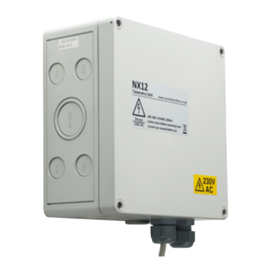
NX12 Micro GSM RTU Enclosure and mounting 6.8.1 DIN Rail option NX12 supplied as a DIN rail mountable unit 6.8.2 Enclosure option NX12 supplied in an IP54 polycarbonate enclosure FRONT OF ENCLOSURE REAR OF ENCLOSURE 90 mm DEPTH SHOWING 4 FIXING HOLES 167.0mm... -
Page 22: Maintenance
Press the button (SW1) at the top left of the PCB. Confirm that the RTU communicates successfully with the iHost system. I/O tests For each input connected to the NX12, confirm that the correct status data and the desired date/time events are being reported to the iHost system. Replacing the Battery When replacement is necessary, contact Nortech for a replacement part. -
Page 23: Recycling
After replacing the internal battery, dispose of the old lithium battery responsibly, in accordance with local rules. NX12 units can be returned to Nortech for recycling at the end of their life. © Nortech Management Ltd, United Kingdom Page 23 of 25... -
Page 24: Specification Data
GSM modem with SMA antenna. NEXUS protocol, supported on the iHost system. AC powered units The NX12 requires a two (2) wire AC supply. Connect with the correct polarity. It is the users’ responsibility to ensure that local wiring regulations are complied with during installation. -
Page 25: Emc
NX12 Micro GSM RTU The NX12 has been designed and manufactured to meet the following standards. Emissions EN61326-1: 2006 Class B Emissions, Industrial locations EN55011 Mains terminal disturbance voltage EN55011 Electromagnetic radiation disturbance EN61000-3-2 Harmonic current emissions EN61000-3-3 Flicker (not applicable)
Need help?
Do you have a question about the NX12 and is the answer not in the manual?
Questions and answers