Advertisement
Quick Links
Advertisement

Summary of Contents for Living 064-3178-8
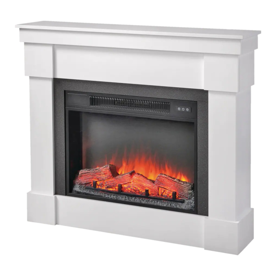
- Page 1 ALTON ELECTRIC FIREPLACE Model No.064-3178-8...
- Page 2 Made in China...
-
Page 3: Replacement Parts List And Exploded View
Operating Instructions Care and Maintenance Troubleshooting Guide Replacement Parts List and Exploded View risk traf c not be hung on it or near it. - Page 4 Model No. 064-3178-8...
- Page 6 Model No. 064-3178-8 Firebox Down Support - 2 Left front panel - 1 Left side panel - 1 Right front panel - 1 Right side panel - 1 Upper front panel - 1 Upper Decorative Panel - 1 Lower front panel - 1...
- Page 7 Wood dowel 7.8 x 30 mm - 54 Firebox L-bracket - 2 Wood dowel 7.8 x 20 mm - 10 Screw 4 x 10 mm - 6 Cam bolt - 18 Fabric strip - 2 Cam - 22 Metal washer - 4 Double-end cam bolt - 2 Wall anchor - 2 Screw 4 x 24 mm - 28...
-
Page 8: Helpful Hints
Model No. 064-3178-8 Read each section carefully before starting. It is very important that each step is performed in the correct order. If these steps are not followed in sequence, assembly dif culties will occur. Make sure all parts are included. Most board parts are labelled or stamped on the raw edge. - Page 9 Step 1 Requires 1, 2, 3, 4, A, C Step 2 Requires 3, A, C, G, H...
- Page 10 Model No. 064-3178-8 Step 3 Requires 7, 8, A Step 4 Requires 7, 8, I...
- Page 11 Step 5 Requires 9, A, C, H, J Step 6 Requires 10, A, C, H, J...
- Page 12 Model No. 064-3178-8 Step 7 Requires 7, 9, 10, D Step 8 Requires 3, 4, 9, 10, D, H...
- Page 13 Step 9 Requires 12, 13, A Step 10 Requires 12, 13...
- Page 14 Model No. 064-3178-8 Step 11 Requires 12, 13, F, I Step 12 Requires 5, 6, B...
- Page 15 Step 13 Requires 5, 6, F Step 14 Requires 5, F Make sure the panels 6 and side panels are aligned. If necessary, adjust screws (F) in step 13 for a good t. Align and attach the top strip panel assembly in place by using screws (F). Make sure the panel 5 and side panels are aligned before tightening the screws (F).
- Page 16 Model No. 064-3178-8 Step 15 Requires 11, D, E, F Step 16 Requires 14, C...
- Page 17 Step 17 Requires 14, D Step 18...
- Page 18 Model No. 064-3178-8 Step 19 Requires F, K, L, M, N WARNING Young children may be injured by tipping furniture.The use of a tipping restraint is highly recommended. This hardware, when properly installed, could provide protection against the unexpected tipping of furniture due...
-
Page 19: Weight Limit
Step 20 Requires I, N, O wall wall Step 21 Enjoy your furniture WEIGHT LIMIT This unit has been designed to support the maximum 64 1/2 lb loads shown. Exceeding this load limit could (29.3 kg) cause sagging, instability, product collapse, and/or serious injury. - Page 20 Model No. 064-3178-8 top right...
- Page 21 Ensure plug ts tightly in the outlet.
- Page 22 Model No. 064-3178-8 type 2025 battery.
- Page 23 7a. Call 1-877-483-6759.
- Page 24 Model No. 064-3178-8 For replacement parts, please call 1-877-483-6759, 7:00 am – 5:00 pm CST, Monday – Friday. Part Part Name Part Part Name Flame Generator Drive Motor Ember bed with Log Flame Effect Circuit Board Heater / Blower Assembly...
Need help?
Do you have a question about the 064-3178-8 and is the answer not in the manual?
Questions and answers