Table of Contents
Advertisement
072-0300
1
2
Product Specification
3
Health And Safety and Regulatory Information
4
How the OPC N2 works
5
PM Measurement
6
Connecting and running the OPC
7
8
Running the OPC N2 using the Alphasense software
•
•
Data Display and taking measurements
•
Other software functions
9
10
Running the OPC N2 using direct API control
11
12
Appendices (order may change!)
A.
B.
C.
Updating Firmware (TBC)
D.
Alphasense Ltd
Sensor Technology House, 300 Avenue West, Skyline 120, Great Notley. Essex.CM77 7AA. UK
Alphasense User Manual
OPC-N2 Optical Particle Counter
Contents
Windows XP
Windows 7
Windows 8, 8.1 and 10
Tel: +44 (0) 1376 556700
Email: sensors@alphasense.com
Page 1 of 34
- Fax: +44 (0) 1376 335899
- Web: www.alphasense.com
Issue 5
December 2015
Advertisement
Table of Contents

Subscribe to Our Youtube Channel
Related Manuals for Alphasense OPC-N2

Summary of Contents for Alphasense OPC-N2
- Page 1 Health and Safety and Regulatory Information How the OPC N2 works PM Measurement Sampling the environment Connecting and running the OPC Connecting Power and Taking Readings Running the OPC N2 using the Alphasense software • Installation • Data Display and taking measurements •...
-
Page 2: Quick Start
072-0300 OPC-N2 Optical Particle Counter Issue 5 Quick Start The purpose of this manual is to explain how to set up, install and use the Alphasense Optical Particle Counter OPC-N2 for measuring PM , PM and PM , as well as measuring particle size distributions in real time. - Page 3 Alphasense User Manual 072-0300 OPC-N2 Optical Particle Counter Issue 5 OPC-N2 Specification All dimensions in millimetres (± 0.15 mm) MEASUREMENT Spherical equivalent size (based on RI of 0.38 to 17 Particle range (μm) 1.5+i0) Size categorisation (standard) Number of software bins...
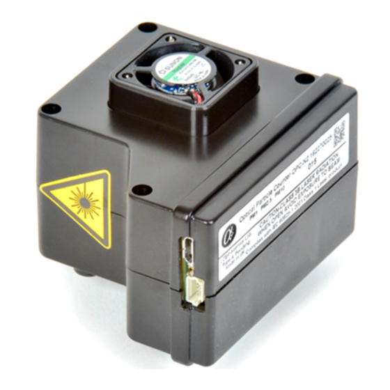
- Page 4 The OPC-N2 uses an embedded diode laser light source that operates at typically 5-8 mW (max. 25 mW) at a wavelength of 658 nm. The OPC-N2 is a Class 1 laser product, since the user does not have access to the laser source. The OPC-N2 is designed for OEM use, normally mounted in a secondary housing.
-
Page 5: Pm Measurement
RI. The OPC-N2 assumes an average RI value of 1.5 + i0. The OPC-N2 allows a different value to be set for each size bin to correct for particle density variation with particle size. The default setting for each size bin is a Particle Density value of 1.65 g/ml, a figure that equates to a typical value found in many... -
Page 6: Sampling The Environment
Alphasense recommends that the OPC-N2 inlet is exposed directly to the target sample volume and that the fan exhaust is left free to exhaust into an unconstrained space. The OPC-N2 can be positioned in any orientation. However, to mitigate the effects of wind direction on sampling it is best for the inlet to be pointing upwards. -
Page 7: Connecting Power And Taking Readings
Alphasense requires a USB A-B lead to connect to the USB port of a computer. The green LED shows that power is supplied to the OPC-N2 and the red LED flashes when the PC and OPC-N2 are communicating. The micro-USB socket can be used for updating the internal firmware and downloading the SD card measured data, it is not possible to download real time data via this socket. -
Page 8: Installation
Connect the USB-SPI interface lead and OPC device to the PC. If you are prompted for device drivers refer to the previous section of the user manual. Double click the OPC-N2.exe icon to start the software application. When the application is first started the main form will be in “start-up mode”... - Page 9 Histogram Counts/s vs Particle Size display mode When the Start sampling button is pressed, the OPC-N2 will first ask if the data are to be saved. Once answered, it will begin to display particle size histogram data and if selected, store data to a file.
- Page 10 Alphasense User Manual 072-0300 OPC-N2 Optical Particle Counter Issue 5 • Data relating to each acquired histogram, including PM values, is given in the right-hand window of the display. The RollMean_PM10, etc., are the current rolling mean values for PM evaluated over the previous 5 minutes or to the beginning of sampling if that is less time.
- Page 11 As the firmware first loads it follows the procedure below: Check for SD memory card. All versions of the OPC-N2 will come with a 16GB micro SD card fitted. This card is internal and is not accessible from outside the case, please note it may not be fitted on early release OPC-N2 units.
- Page 12 OPC-N2 Optical Particle Counter Issue 5 If a SD card is found, the OPC will check for a USB connection. The OPC-N2 comes equipped with a micro USB port. 2. If a USB connection is found the device will switch to “USB mode”. This makes the OPC-N2 behave like an external storage device (pen-drive) until the USB is disconnected.
- Page 13 Sample volume 1 ….. 1 Individual additional bin weighting weighting for bin Annotated CSV produced by an OPC-N2 run by the Alphasense Software top section Alphasense Ltd Page 13 of 34 December 2015 Sensor Technology House, 300 Avenue West, Skyline 120, Great Notley. Essex.CM77 7AA. UK...
- Page 14 Annotated CSV produced by an OPC-N2 run by the Alphasense Software bottom section For CSVs generated in standalone mode the main difference is that the bin count is the total count in the sampling period and is not a count/s...
-
Page 15: Standalone Mode (Recording To Onboard Sd Card
Standalone mode (Recording to onboard SD card) If the OPC-N2 unit is powered but receives no SPI communication for 60s it starts running and logs data to the on board SD card. The default settings are such that it will run with the fan and laser on continuously and record a histogram every ~1.4s. -
Page 16: Revision Control
Running the OPC N2 using direct SPI control Full details of the SPI commands and connections are given for the OPC-N2. This is should be sufficient for the user to be able to design their own SPI system to control the device and gather data. - Page 17 Older Units, other Firmware 15 variants and 14 Substantial improvements have been made since these units have been issued. It is not possible to update these units in the field. Please Contact Alphasense to discuss potential upgrade options. • Can the OPC be connected to a gas flow at 500 SCCM (or similar)? •...
- Page 18 • Raspberry Pi and Arduino • The OPC-N2 is ideally suited to be operated by devices such as Raspberry Pi or Arduino via its SPI interface. While Alphasense does not yet distribute example OPC-N2 control programs to be used on these devices, many of its customers have successfully implemented such control programs following the OPC-N2 SPI commands list.
- Page 19 Alphasense User Manual 072-0300 OPC-N2 Optical Particle Counter Issue 5 Appendix B: Installing the device driver Windows XP Copy the folder “OPC Interface Software” to the PC desktop. Connect the USB interface lead to the PC. If the USB interface lead (USB to SPI...
- Page 20 Alphasense User Manual 072-0300 OPC-N2 Optical Particle Counter Issue 5 Windows 7 Copy the folder “OPC Interface Software” to the PC desktop. Connect the USB interface lead to the PC. If the USB interface lead (USB to SPI converter) is connected to...
- Page 21 Alphasense User Manual 072-0300 OPC-N2 Optical Particle Counter Issue 5 Right click the icon and select “Update Driver Software”. Select the “Browse my computer for driver software” option. Navigate to the folder “OPC Interface Software” copied to your desktop and locate the folder named “USB Driver”,...
- Page 22 Alphasense User Manual 072-0300 OPC-N2 Optical Particle Counter Issue 5 Windows 7 will then issue a security warning. This is due to a licence issue and not a concern to the operating system. Select the “Install this driver software anyway”...
- Page 23 Alphasense User Manual 072-0300 OPC-N2 Optical Particle Counter Issue 5 Windows 8, 8.1 and 10 This procedure will guide you through the process of disabling the digital device driver verification in Windows 8, 8.1 and 10. The method for 8.0 is different than for 8.1 and 10 Background 64-Bit editions of Windows require digitally signed drivers.
- Page 24 Alphasense User Manual 072-0300 OPC-N2 Optical Particle Counter Issue 5 Then click on the Recovery option on the left hand side. Once selected, you will see an advanced startup section appear on the right hand side. You will need to click on the “Restart now”...
- Page 25 Alphasense User Manual 072-0300 OPC-N2 Optical Particle Counter Issue 5 Then Startup Settings. Since we are modifying boot time configuration settings, you will need to restart your Computer one last time. Finally, you will be given a list of startup settings that you can change.
- Page 26 Alphasense User Manual 072-0300 OPC-N2 Optical Particle Counter Issue 5 To disable the signature verification it is necessary to get into Troubleshooting options from the boot manager. Select Restart from the power options menu (for Windows 8 this is under...
- Page 27 Alphasense User Manual 072-0300 OPC-N2 Optical Particle Counter Issue 5 Since we are modifying boot time configuration settings, you will need to restart your Computer one last time. Finally, you will be given a list of startup settings that you can change.
- Page 28 OPC-N2 Optical Particle Counter Issue 5 Appendix C: Updating the Firmware It is possible to update the firmware on the OPC-N2 device using the supplied Bootloader tool when running firmware version 0015d (and above). To upgrade the firmware on your OPC-N2 device requires: •...
- Page 29 Alphasense User Manual 072-0300 OPC-N2 Optical Particle Counter Issue 5 4. The Bootloader tool will automatically initialise if connected via USB and if the software is in Bootloader mode. The text on the Bootloader form will change to confirm that...
- Page 30 Alphasense User Manual 072-0300 OPC-N2 Optical Particle Counter Issue 5 Appendix D: Summary of firmware commands OPC-N2 SPI functions (from point of view of SPI Master system) for firmware version 18. Function Firmware Command Byte(s) out Byte(s) in (0xF3 is set as...
- Page 31 Alphasense User Manual 072-0300 OPC-N2 Optical Particle Counter Issue 5 byte and following byte. 0x00 0x42 FanDAC is a unsigned 8bit integer variable. FanDAC 0x00 Digital pot 0x13 0x13 0xF3 Suggest that 10ms be Read Status used as delay between command byte and following byte.
- Page 32 Alphasense User Manual 072-0300 OPC-N2 Optical Particle Counter Issue 5 0x3F InfoStr ascii char24: “1” (=0x31) “ 0x3F InfoStr ascii char25: “6” (=0x36) “ 0x3F …….. “ See separate Doc for details 0x3F InfoStr ascii char59: “.” (=0x2E) Read serial...
- Page 33 Alphasense User Manual 072-0300 OPC-N2 Optical Particle Counter Issue 5 is unsigned 8bit integer variable (1 or Write 0x3B 0x3B 0xF3 Suggest that 10ms be Configuration used as delay Variables 2 between command byte and following byte. AMSamplingInterv 0x3B AMSamplingIntervalC...
- Page 34 Alphasense User Manual 072-0300 OPC-N2 Optical Particle Counter Issue 5 0x32 PM10 Byte2 0x32 PM10 Byte3 Save 14/15 0x43 0x43 0xF3 Suggest that 10ms be Configuration 16/17 used as delay Variables in between command non-volatile byte and following memory byte.
Need help?
Do you have a question about the OPC-N2 and is the answer not in the manual?
Questions and answers