
Summary of Contents for LOFTNESS 51CCH
- Page 1 Carbide Cutter 51CCH • 61CCH • 71CCH Owner’s Manual and Parts Book (Originating w / Serial Number 42-751) Model Number: Serial Number: Date of Purchase: N28364 09.26.14...
- Page 3 LOFTNESS factory or authorized LOFTNESS dealership or in any way so as in LOFTNESS’ judgment, to affect its stability or reliability, nor which has been subject to misuse, negligence or accident, nor to any machine or attachment which shall not have been operated in accordance with LOFTNESS’...
- Page 5 650 South Main Street Hector, MN 55342 USA loftness.com 320-848-6266 US & Canada 800-828-7624 International: 320-848-6266 Fax: 320-848-6269 Parts Fax: 320-848-6055 E-mail: info@loftness.com Web Address: www.loftness.com WARRANTY REGISTRATION Dealer No.: Dealer Phone: Dealer Name: Shipping Address: Mailing Address: State: Zip: City: Invoice No.:...
- Page 7 650 South Main Street Hector, MN 55342 USA loftness.com 320-848-6266 US & Canada 800-828-7624 International: 320-848-6266 Fax: 320-848-6269 Parts Fax: 320-848-6055 E-mail: info@loftness.com Web Address: www.loftness.com WARRANTY REGISTRATION Dealer No.: Dealer Phone: Dealer Name: Shipping Address: Mailing Address: State: Zip: City: Invoice No.:...
-
Page 9: Table Of Contents
Table of Contents Warranty Table of Contents Ordering Code Ordering Code ............. . .1 Carbide Cutter (Example) . - Page 10 Table of Contents Maintenance (Cont'd) Tooth Removal and Installation ..........23 Double Tooth &...
-
Page 11: Ordering Code
Ordering Code Ordering Code Carbide Cutter (Example) The ordering code will consist of two numbers (machine size), three letters (machine type), one letter (cutter type), three numbers (motor system), one letter (sheaves / belt combo), one number (threshold setting), and two letters (options). An example for a carbide cutter of this type would be as shown below. - Page 12 Carbide Cutter OM...
-
Page 13: Introduction
Continuous improvement and advancement of Loftness products may result in changes to your equipment that may not be reflected in this publication. Loftness reserves the right to make product improvements to the machine at any time. Although great care has been taken to ensure the accuracy of this publication, Loftness does not assume any liability for errors or omissions. -
Page 14: Carbide Cutter Features
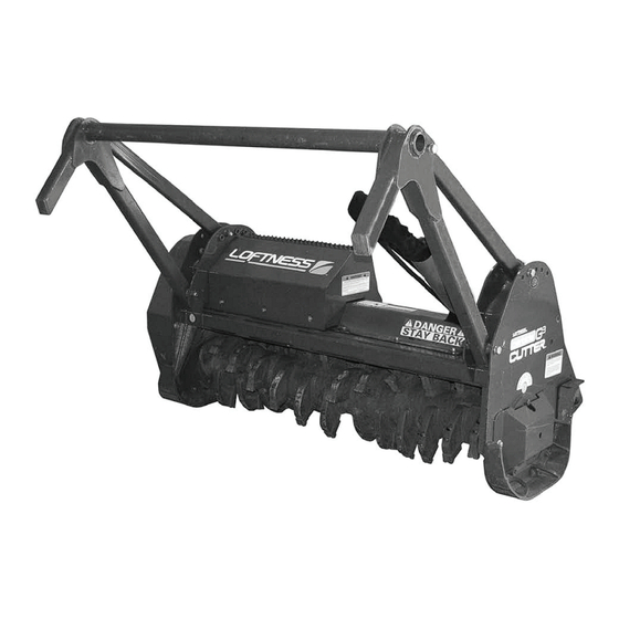
Introduction Carbide Cutter Features Carbide Cutter Options • Downward Rotation Design • Premium Strength Steel Body & Rotor • Carbide Planer Teeth • Front Mounted • Quadco Planer Teeth (Sharpenable) • Hydraulic Driven • Universal Skid-Steer Mount • Adjustable Tree Pusher •... -
Page 15: Safety Instructions
Be certain all machine operators are aware of the dangers indicated by safety decals applied to the machine, and be certain they follow all safety decal Safety Alert Symbol instructions. Contact Loftness for safety decal replacement. This message alert symbol identifies important safety messages on the machine... -
Page 16: Mandatory Shut-Down Procedure
Safety Instructions Mandatory Shut-Down Procedure • Use the handholds and step plates when getting on and off the machine to prevent falls. Keep steps and platform cleared of mud and debris. • Stop the machine and attachment on a level surface and lower the attachment to the ground. -
Page 17: Hydraulic Safety
Safety Instructions • Keep children, bystanders and other workers off • Operators are responsible to know the location and away from the machine and attachment during and function of all guards and shields including but operation. No riders allowed. not limited to belt drives and rotor. Operators are responsible to make certain that all guards are in •... -
Page 18: Carbide Cutter Identification
Safety Instructions Carbide Cutter Identification Pusher Bar Hydraulic Control Valve Hydraulic Motor Rotor Bearing Guard Rotor Cutting Teeth Skid Hydraulic Hoses Pressure Gauge Hydraulic Hose Support Rotor Locking Pin (Storage Location) Drive Belt Mounting Plate Deflector Chain Support Stand Carbide Cutter OM... -
Page 19: Safety Decal Locations
Safety Instructions Safety Decal Locations Check and replace any worn, torn, hard to read or missing safety decals on your machine. WARNING Rotor must be stabilized with the rotor locking pin to prevent accidental rotation any time the rotor is exposed for service work. - Page 20 Safety Instructions Safety Decal Locations (Cont’d) DANGER STAY BACK KEEP HANDS AND FEET WARNING AWAY FROM ROTATING KNIVES UNDER MACHINE Read and understand operator’s manual before DO NOT LEAVE using this machine. OPERATORS POSITION Failure to follow operating instructions could result WHILE POWER UNIT IS in death or serious injury.
- Page 21 MACHINE UNTIL YOU HAVE CAREFULLY READ AND THOROUGHLY UNDERSTAND THE CONTENTS OF THE OPERATOR'S MANUAL. NOTE: IF YOU DO NOT HAVE AN OPERATOR'S MANUAL, CONTACT YOUR DEALER OR LOFTNESS SPECIALIZED EQUIPMENT 650 SOUTH MAIN HECTOR, MN 55342 1-800-828-7624 FAILURE TO FOLLOW SAFETY, OPERATING, AND...
- Page 22 Carbide Cutter OM...
-
Page 23: Set-Up Instructions
Set-up Instructions Installing the Carbide Cutter to the Loader Fully raise the attachment-locking levers on the loader mounting plate. NOTE: The hydraulic hose quick couplers shown above are not supplied with the carbide cutter. Install the carbide cutter quick couplers to the loader. NOTE: The case drain quick coupler (1) of the carbide cutter must be connected to the loader’s auxiliary hydraulic system for proper operation of the... -
Page 24: Checking Rotor Rotation
Set-up Instructions Checking Rotor Rotation Checking Rotor Speed NOTE: To order a Diagnostic Gauge Kit use # N16340. Raise the carbide cutter off the ground and place blocks (1) underneath the skids. Lower the carbide cutter down on the blocks. NOTE: The electronic or mechanical tachometer shown above is not supplied with the carbide cutter. -
Page 25: Pusher Bar Adjustment
Set-up Instructions Pusher Bar Adjustment Adjusting the Support Stands Approved Lifting Device Remove the two bolts (1) and support stand (2). Repeat NOTE: Adjusting the pusher bar requires two people or procedure on opposite side. the use of an approved lifting device to support the push bar as it is being adjusted. -
Page 26: Skid Adjustment
Set-up Instructions Skid Adjustment WARNINg: Do not remove the locking pin for any reason when one or more knives are missing from the rotor assembly. The imbalance could cause the rotor to turn without warning causing serious personal injury. NOTE: The skid(s) can be adjusted to increase or decrease the distance between the ground and the rotor. -
Page 27: Operating Instructions
300 feet of the work area above the rated RPM. Check with your while operating this machine. Loftness dealer to be sure your attachment is set-up with the correct hydraulic motor to Lower the carbide cutter until the skids contact the match the hydraulic flow GPM (Gallons Per ground. -
Page 28: Log Moving
Operating Instructions Log Moving Disengage the loader auxiliary hydraulics. Raise the loader lift arms and tilt the carbide cutter forward until the push bar extensions are over the log or item being moved. Lower the lift arms and position the log between push bar extensions and the carbide cutter. -
Page 29: Maintenance
Maintenance general Maintenance Maintenance Schedule To ensure efficient operation, you should inspect, lubricate, SERVICE REQUIRED and make necessary adjustments and repairs at regular intervals. Parts that are starting to show wear should be ordered ahead of time, before a costly breakdown occurs SERVICE POINTS and you have to wait for replacement parts. -
Page 30: Lubrication
Maintenance Lubrication grease Point Location Rotor Bearing, left Belt Tensioner Rotor Bearing, right Carbide Cutter OM... -
Page 31: Overhung Load Adapter
Maintenance grease Points Location (Cont'd) • Belt Tensioner grease Fitting Location: (3) - Located at the base of the front push bar Use a #2 general purpose lithium based grease unless arm, right side. Lubricate the fitting through noted otherwise. the opening of the frame, (top grease fitting). -
Page 32: Belt Adjustment
Maintenance Belt Adjustment Remove the six bolts (1) and drive belt cover (2). Turn the adjustment bolt clockwise until the distance from the collar (5) to the end of the spring (6) is approximately Loosen jam nut (3). 10 - 1/4". Tighten jam nut (5). Turn adjustment bolt (4) clockwise to increase spring tension. -
Page 33: Tooth Removal And Installation
Maintenance Tooth Removal and Installation Tooth Sharpening (Quadco Option Only) Double Tooth & Double Planer NOTE: The teeth need to be kept sharp to maintain the Install the rotor locking pin. See “Rotor Locking Pin most effective operation of the attachment. Daily Installation”... -
Page 34: Storage
Maintenance Tooth Sharpening (Quadco Option Storage Only) - Cont'd End of Season NOTE: When re-sharpening teeth using a hand grinder, • Clean entire carbide cutter thoroughly. avoid overheating the tooth by lightly grinding each tooth, moving across the entire row of teeth •... -
Page 35: Motor & Sheave Selection Chart
Maintenance Motor & Sheave Selection Chart VARIABLE DISPLACEMENT LOFTNESS ROTOR RPM TOP SHEAVE (LOFTNESS NUMBER) DISPLACEMENT PART BOTTOM SHEAVE ( LOFTNESS NUMBER) MOTOR NUMBER NUMBER BELT LENgTH (LOFTNESS NUMBER) 1762-1321 1819-1364 1875-1406 9.0 Top Sheave (N20806) 60cc - 80cc 9.75 Bottom Sheave (N18974) -
Page 36: Troubleshooting
Maintenance Troubleshooting PROBLEM CAUSE SOLUTION Excessive Vibration Broken or missing teeth. Replace teeth. Mud and/or debris wrapped around Clean the carbide cutter. the rotor. Faulty drive line bearing. Replace bearing(s). Faulty rotor bearing. Replace bearing(s). Damage to rotor (includes bent end Consult factory. -
Page 37: Parts Identification
Parts Identification PARTS IDENTIFICATION Carbide Cutter OM... -
Page 38: Carbide Cutter Drive Assembly
Parts Identification Carbide Cutter Drive Assembly (CODE H) (CODE F) (CODE J) * - Item 10 is not a replacement part. Carbide Cutter OM... - Page 39 Parts Identification Carbide Cutter Drive Assembly QTY. PART # DESCRIPTION 4054 NUT, LOCK 1/2" TOP N28333 HOLDER, HOSE WELDMENT 4154 BOLT, 1/2" X 3 - 1/2" GRADE 5 4005 BOLT, 3/8" x 1 - 1/4" GRADE 5 4065 WASHER, 3/8" LOCK 4064 WASHER, FLAT 3/8"...
-
Page 40: Carbide Cutter Body Assembly
Parts Identification Carbide Cutter Body Assembly * - Item 8 is not a replacement part. Carbide Cutter OM... - Page 41 Parts Identification Carbide Cutter Body Assembly QTY. PART # DESCRIPTION 4244 BOLT, 3/4" x 4 - 1/2" GRADE 5 N21094 PUSHER, 51" CARBIDE N20100 PUSHER, 61" CARBIDE N20167 PUSHER, 71" CARBIDE N19048 ARM, CARBIDE PUSHER MECHANICAL 4029 BOLT, 3/4" x 6" GRADE 5 4287 WASHER, 3/4"...
-
Page 42: Carbide Cutter Body Assembly (Cont'd)
Parts Identification Carbide Cutter Body Assembly (Cont'd) Carbide Cutter OM... - Page 43 Parts Identification Carbide Cutter Body Assembly (Cont'd) QTY. PART # DESCRIPTION N16417 BEARING, 2 - 3/16" PILOT ROLLER N20059 MOUNT, CARBIDE ROTOR BEARING N18929 ANTIWRAP, CARBIDE MACHINED 2 - PIECE N20083 ROTOR, 51" CARBIDE WITH DOUBLE CUTTERS N20077 ROTOR, 61" CARBIDE WITH DOUBLE CUTTERS N20080 ROTOR, 71"...
-
Page 44: Carbide Cutter Body Assembly (Cont'd)
Parts Identification Carbide Cutter Body Assembly (Cont'd) 10 (To belt tensioner) 10 (To bearing) 6 14 Carbide Cutter OM... - Page 45 Parts Identification Carbide Cutter Body Assembly (Cont'd) QTY. PART # DESCRIPTION N19600 HOLDER, MANUAL 4340 BOLT, 1/4" x 3/4’ GRADE 5 4071 WASHER, 3/4" FLAT 4287 WASHER, 3/4" LOCK 4244 BOLT, 3/4" x 4 - 1/2" BOLT GR 5 N17007 GREASE - ZERK, 1/8 NPT 4472 ELBOW, 1/8"...
-
Page 46: Motor Assembly #530 Open (N28409)
Parts Identification Motor Assembly #530 Open (N28409) TO MOTOR COVER PRESSURE GAUGE 11 12 TO CASE DRAIN Valve Open Loop CW (N21669) Schematic * Item 3 (N21669) parts breakdown. 3a** 1000 PSI 6000 PSI 3b*** 3c*** 3d** Oil Flow Direction “Forward”... - Page 47 Parts Identification Motor Assembly #530 Open (N28409) QTY. PART # DESCRIPTION N28893 ADAPTER, - 6FJIC - 6FP N28907 ELBOW, 90DEG - 6MJIC - 4MOR N21669 VALVE, OPEN LOOP CW N28100** RELIEF, LOW PRESSURE 1000PSI N28102*** VALVE, CHECK PILOT OPERATED N28103*** VALVE, COUNTERBALANCE N28099** RELIEF, HIGH PRESSURE 5000PSI...
-
Page 48: Motor Assembly #630 Closed (N28410)
Parts Identification Motor Assembly #630 Closed (N28410) TO MOTOR COVER PRESSURE GAUGE TO CASE DRAIN REAR OF MOTOR Relief Valve Closed Loop CW (N23026) Schematic * Item 2 (N23026) parts breakdown. 2a** PURGE 3-5 GPM LPRV HPRV 1000 PSI 6000 PSI Oil Flow Direction “CW”... - Page 49 Parts Identification Motor Assembly #630 Closed (N28410) QTY. PART # DESCRIPTION N16066 ELBOW, - 6 MOR - 6FP / 90 DEG N23026 VALVE, RELIEF CLOSED LOOP CW N28100** VALVE, RELIEF LOW PRESSURE 1000PSI N28101 VALVE, HOT OIL SHUTTLE N28098 VALVE, PURGE FLOW CONTROL N28099** VALVE, RELIEF HIGH PRESSURE 5000PSI N20976...
-
Page 50: Motor Assembly #933 Open 15 Bar (N28472)
Parts Identification Motor Assembly #933 Open 15 Bar (N28472) TO ACCUMULATOR 7 MOTOR COVER PRESSURE GAUGE TO CASE DRAIN Relief Valve Open Loop CW (N28203) Schematic SAE-10 SAE-10 VT1385-CW ASSEMBLY * Item 3 (N28203) parts breakdown. HPRV SAE-8 SAE-8 3a** LPRV 3d** 3b***... - Page 51 Parts Identification Motor Assembly #933 Open 15 Bar (N28472) QTY. PART # DESCRIPTION N28353 BOLT, SHCS 3/8" x 3 - 1/4" N21916 WASHER, HIGH COLLARLOCK 3/8" N28203 VALVE, RELIEF OPEN LOOP CW N28100** VALVE, RELIEF LOW PRESSURE 1000PSI N28102*** VALVE, CHECK PILOT OPERATED N28103*** VALVE, COUNTERBALANCE N28099**...
-
Page 52: Motor Assembly #1033 Closed 15 Bar (N28500)
Parts Identification Motor Assembly #1033 Closed 15 Bar (N28500) MOTOR COVER PRESSURE GAUGE MOTOR CASE DRAIN TO CASE DRAIN Relief Valve Open Loop CW (N28636) Schematic * Item 3 (N28636) parts breakdown. 3a** 3d** ** Use item 24 in parts list, part number N38181, for seal kit for items 3a and 3d. - Page 53 Parts Identification Motor Assembly #1033 Closed 15 Bar (N28500) QTY. PART # DESCRIPTION N28353 BOLT, SHCS 3/8" X 3-1/4" N21916 WASHER, HIGH COLLARLOCK 3/8" N28636 VALVE, RELIEF CLOSED LOOP CW N28100** VALVE, RELIEF LOW PRESSURE 1000 PSI N28098 VALVE, PURGE FLOW CONTROL N28101 VALVE, HOT OIL SHUTTLE N28099**...
-
Page 54: Motor Assembly, Voac 60 (N20840)
Parts Identification Motor Assembly, VOAC 60 (N20840) QTY. PART # DESCRIPTION N28563 REBUILD SEAL KIT (Items with asterisk are included in seal kit.) N28173 SHAFT SEAL 45 X 65 X 7 Carbide Cutter OM... -
Page 55: Overhung Load Adapter (N20901)
Parts Identification Overhung Load Adapter (N20901) QTY. PART # DESCRIPTION N28566 REBUILD KIT (Includes Items 1, 2, 3, 4, and 6.) N28447 SEAL, FRONT N34130 CUP BEARING N34131 CONE BEARING N28448 SEAL, REAR N34132 RETAINING RING N14159 GASKET Carbide Cutter OM... -
Page 56: Variable Motor Assembly, 15 Bar (N28205)
Parts Identification Variable Motor Assembly, 15 Bar (N28205) QTY. PART # DESCRIPTION N28560 REBUILD SEAL KIT (Items with asterisk are included in seal kit.) N28173 SHAFT SEAL 60 X 80 X 7 Carbide Cutter OM... -
Page 57: Hydraulic Hose Assembly (N28471)
Parts Identification Hydraulic Hose Assembly (N28471) QTY. PART # DESCRIPTION N28273 HOSE, 1" X 126" HYD W/O SLEEVE -16MORB B.E. N28108 ADAPTER, - 12MOR - 16FOR N32001 PLUG, 1.00 X .3125 N15893 CAP, 3/4" ALUMINUM HOSE N15895 CAP, 1/2 ALUMINUM HOSE N32002 PLUG, 3/8 SCH 40 X .25 N28358... -
Page 58: Belt Tensioner (N28018)
Parts Identification Belt Tensioner (N28018) QTY. PART # DESCRIPTION 4459 BOLT, 5/8" x 3" GRADE 8 N16473 WASHER, 5/8" NORDLOCK N10508 PULLEY, IDLER BELT Varies N28269 WASHER, HARDENED 5/8" x 1 - 3/4" N28382 SLIDE, BELT TIGHT SQ ASSY N24211 SPRING, BELT TIGHTENER 4250 NUT, STANDARD 1/2"... -
Page 59: Motor Shield W / Gauge (N15974)
Parts Identification Motor Shield W / gauge (N15974) QTY. PART # DESCRIPTION N20209 SHIELD, CARBIDE MOTOR N16334 NUT, NYLON INSERT #10 N16162 ELBOW, 1/4" NPT 90 DEG STREET N16335 FLANGE, MOUNT #10 N16331 FLANGE, MOUNT GAUGE #8 N16332 FLANGE, MOUNT GAUGE N16067 HOSE, 1/4"... -
Page 60: Rotor (W / Double Carbide Teeth) 51" (N20083), 61" (N20077), 71" (N20080)
Parts Identification Rotor (W / Double Carbide Teeth) 51" (N20083), 61" (N20077), 71" (N20080) * Use copper based anti-seize. Torque to 137 ft.-lbs. Tighten top bolt (Item 4) first. QTY. PART # DESCRIPTION N20084 ROTOR, 51" CARBIDE SPIRAL W / O CUTTERS N20078 ROTOR, 61"... -
Page 61: Rotor (W / Carbide Planer Teeth) (Optional) 51" (N20576), 61" (N20575), 71" (N21906)
Parts Identification Rotor (W / Carbide Planer Teeth) (Optional) 51" (N20576), 61" (N20575), 71" (N21906) * Use copper based anti-seize. Torque to 137 ft.-lbs. Tighten top bolt (Item 4) first. QTY. PART # DESCRIPTION N20084 ROTOR, 51" CARBIDE SPIRAL W / O CUTTERS N20078 ROTOR, 61"... -
Page 62: Rotor (W / Quadco Planer Teeth) (Optional) 51" (N24689), 61" (N28165), 71" (N28168)
Parts Identification Rotor (W / Quadco Planer Teeth) (Optional) 51" (N24689), 61" (N28165), 71" (N28168) * Use copper based anti-seize. Torque to 137 ft.-lbs. Tighten top bolt (Item 5) first. QTY. PART # DESCRIPTION N20084 ROTOR, 51" CARBIDE SPIRAL W / O CUTTERS N20078 ROTOR, 61"... -
Page 63: Tooth Assembly, Quadco Planer (N24281)
Parts Identification Tooth Assembly, Quadco Planer (N24281) QTY. PART # DESCRIPTION N24279 TOOTH, QUADCO PLANER N24139 HOLDER, TOOTH QUADCO PLANER N17041 WASHER, LOCK 5/8" N26490 SCREW, SHCS 5/8"-18UNF X 3-1/4" N17036 SCREW, SHCS 5/8"-18UNF X 2" Carbide Cutter OM... -
Page 64: Rear Cutter Bar 51" (N20282), 61" (N20281), 71" (N21908)
Parts Identification Rear Cutter Bar 51" (N20282), 61" (N20281), 71" (N21908) QTY. PART # DESCRIPTION N20264 PLATE, 51" CARBIDE CUTTER N20238 PLATE, 61" CARBIDE CUTTER N21909 PLATE, 71" CARBIDE CUTTER 4452 NUT, 5/8" - 18UNF STANDARD FINE THREAD (51") 4452 NUT, 5/8"... -
Page 65: Machine Decals And Signs
Parts Identification Machine Decals and Signs Part No. N16759 WARNING NOTE: All safety related decals are also shown in the Safety Instructions Section along with their Rotor must be stabilized with the rotor locking pin location on the machine. See “Safety Decal to prevent accidental rotation any time the rotor is Locations”... - Page 66 MACHINE UNTIL YOU HAVE CAREFULLY READ AND THOROUGHLY UNDERSTAND THE CONTENTS OF THE OPERATOR'S MANUAL. NOTE: IF YOU DO NOT HAVE AN OPERATOR'S MANUAL, CONTACT YOUR DEALER OR LOFTNESS SPECIALIZED EQUIPMENT 650 SOUTH MAIN HECTOR, MN 55342 1-800-828-7624 FAILURE TO FOLLOW SAFETY, OPERATING, AND...
- Page 67 Parts Identification Machine Decals and Signs (Cont’d) Part No. N33105 Part No. N26973 Part No. N28577 Part No. N28504 Part No. N28505 Part No. N13517 Part No. 4138 FEMA Carbide Cutter OM...
- Page 68 Carbide Cutter OM...
-
Page 69: Appendix
Appendix Specifications DESCRIPTION CARBIDE CUTTER Cutting Width 51 in. (129.5 cm) 61 in. (154.9 cm) 71 in. (180.3 cm) Operating Capacity 6 in. (15.2 cm) Continuous 10 in. (25.4 cm) Intermittent Capacity Monitor Pressure Gauge Motor Fixed Piston (#5 & #6 Hyd Systems) Variable Displacement, (#9 &... -
Page 70: Dimensions
Appendix Dimensions CARBIDE CUTTER DESCRIPTION Cutting Width (A) 51.02 in. (129.59 cm) 61.02 in. (154.99 cm) 71.02 in. (180.39 cm) Overall Width (B) 68.56 in. (174.14 cm) 78.56 in. (199.54 cm) 88.56 in. (224.94 cm) Operating Height (C) 35.81 in. (90.96 cm) 35.81 in. -
Page 71: Torque Specifications
Appendix Torque Specifications Inches Hardware and Lock Nuts TORQUE CHARTS Minimum Hardware Tightening Torques Normal Assembly Applications (Standard Hardware and Lock Nuts) Nominal Unplated Plated Unplated Plated Unplated Plated Grade Grade Size W / ZnCr W / ZnCr W / ZnCr W / Gr. -
Page 72: Metric Hardware And Lock Nuts
Appendix Torque Specifications (Cont’d) Metric Hardware and Lock Nuts TORQUE CHARTS Minimum Hardware Tightening Torques Normal Assembly Applications (Metric Hardware and Lock Nuts) Class 5,8 Class 8,8 Class 10,9 Lock nuts Nominal Unplated Plated Unplated Plated Unplated Plated Class 8 Size W / ZnCr W / ZnCr... - Page 74 Loftness Specialized Equipment, Inc. 650 So. Main Street • PO Box 337 • Hector, MN 55342 Tel: 320.848.6266 • Fax: 320.848.6269 • Toll Free: 1.800.828.7624 Printed in USA © Loftness 2014...
Need help?
Do you have a question about the 51CCH and is the answer not in the manual?
Questions and answers