Table of Contents
Advertisement
CLEVER CONTROL
Version: V3
INSTALLATION AND FUNCTIONING MANUAL
USER AND BASIC VERSION
Please, read these instructions carefully before attempting installation
SECURITY ADVISE SIMBOLS
Attention, Danger, Safety Advice!
Danger from electric current of high voltage!
Injuries risk!
Important Information!
AIRDOM07100-R2 (03-02-16)
Advertisement
Table of Contents

Subscribe to Our Youtube Channel
Summary of Contents for Airtecnics CLEVER CONTROL V3
- Page 1 CLEVER CONTROL Version: V3 INSTALLATION AND FUNCTIONING MANUAL USER AND BASIC VERSION Please, read these instructions carefully before attempting installation SECURITY ADVISE SIMBOLS Attention, Danger, Safety Advice! Danger from electric current of high voltage! Injuries risk! Important Information! AIRDOM07100-R2 (03-02-16)
-
Page 2: Table Of Contents
INDEX CLEVER CONTROL CHARACTERISTICS ......................... 3 CLEVER KIT INCLUDES ..............................5 INTELLIGENT PCB ................................5 CONNECTION DIAGRAM - TEMPERATURE SENSOR SHIELDED CABLE ..............6 CONNECTION DIAGRAM - AIR CURTAIN - 1 Clever Control managing 1 unit (1 PCB) ........... 6 CONNECTION DIAGRAM –... -
Page 3: Clever Control Characteristics
CLEVER CONTROL CHARACTERISTICS CLEVER, the new advanced total control, leads the new generation in air curtains management: Maximum control + maximum energy saving. Clever automatically adapts the functioning of the air curtain to the entrance climatic conditions in order to keep the comfort and energy saving. - Page 4 CLEVER CONTROL CHARACTERISTICS TIMER / CALENDAR Once programmed, the air curtain starts and turns off according to the client needs. Calendar function to turn ON/OFF automatically the unit depending on each different day of the week or predefined groups of days. User can select between Day or Night modes with 2 different Set temperatures in order to save energy.
-
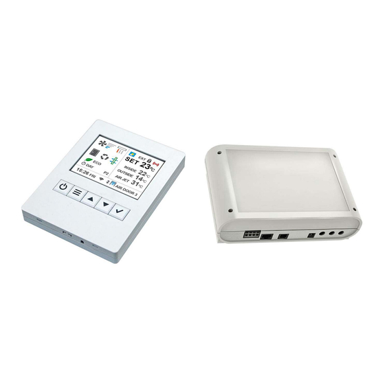
Page 5: Clever Kit Includes
CLEVER KIT INCLUDES Clever Control RJ11 Cable • Easy Plug & Play installation • Colour TFT screen 2.8 inch • RJ11 (4 Pins), 7m length • 114 (h) x 85 (w) x 14 (d) mm (RJ45 (8 Pins) 7/10 m length cable is •... -
Page 6: Connection Diagram - Temperature Sensor Shielded Cable
CONNECTION DIAGRAM - TEMPERATURE SENSOR SHIELDED CABLE CONNECTION DIAGRAM - AIR CURTAIN - 1 Clever Control managing 1 unit (1 PCB) -
Page 7: Connection Diagram - Air Curtain - 1 Clever Control Managing Multiple Units (+1 Pcb)
CONNECTION DIAGRAM – AIR CURTAIN - 1 Clever Control managing multiple units (+1 PCB) Please consult the operating manual of the air curtain for multiple units connection Connection Diagram – FAN HEATER - 1 Clever Control managing 1 unit (1 PCB) -
Page 8: Connection Diagram - Basic Fan Heater - 1 Clever Control Managing Multiple Units (+1 Pcb)
Connection Diagram – BASIC FAN HEATER - 1 Clever Control managing multiple units (+1 PCB) Connection Diagram – HORIZONTAL FAN HEATER - 1 Clever Control managing multiple units (+1 PCB) Please consult the instruction manual of the fan heater for multiple units connection. -
Page 9: Wiring Diagram - 1 Clever Control With 1 Intelligent Pcb
Wiring Diagram – 1 Clever Control with 1 Intelligent PCB... -
Page 10: Wiring Diagram - 1 Clever Control With 2 Intelligent Pcb
Wiring Diagram - 1 Clever Control with 2 Intelligent PCB... -
Page 11: Modify Modbus Address
MODIFY MODBUS ADDRESS By default the Modbus address of Clever PCB is 1. If more than one PCB is connected in serial using Modbus protocol, you should give different Modbus addresses to each PCB board (you can choose from 1 to 255). The Modbus addresses should be introduced using a binary code to the switch SW1 as examples shown in this table: PCB number (decimal) Binary code... -
Page 12: Clever Tft Control
CLEVER TFT CONTROL MAIN STATE SCREEN Main state screen indicates of the most important settings including: Ventilation speed, heating, temperatures, door state, working mode and program, filter state, day/hour, timer, etc…... -
Page 13: Main State Screen Functions
MAIN STATE SCREEN FUNCTIONS FAN SPEED Indicates the fan speed (stages or proportional) Indicates the heating type (electrical, water, heat pump) and state (heating stage, ON/OFF or proportional, heating/cooling) HEATING TYPE / STAGES The last sign on the right is the anti-freezing protection at water heated units (safety program to protect the water coil) DOOR STATE Indicates if the door is open or closed... -
Page 14: Buttons Navigation
BUTTONS NAVIGATION When you are managing Control Clever, text in blue color or flashing sign indicates where you currently are. Turn ON /OFF the equipment When multi equipment (more than 1 unit) it will ask if you want to turn ON/OFF the current unit or all State Go to User Menu... -
Page 15: User Menu
USER MENU Exit Menu (if you are in first level) MENU Go back to previous menu screen (if you are in level 2 or higher) BACK When editing the name, time, hour, etc… it goes back to the previous value SCROLL UP/DOWN Scroll through option (left) or editing value (between arrows) GO NEXT/BACK... -
Page 16: User Menu / Time Programmer
User Menu / TIME PROGRAMMER By default it’s OFF, showed as "Disable" To activate to turn it into "Enable" and press “✓” button to activate it and show all the options TIME PROGRAMMER MENU - SCREENS 1 y 2 Enable / Disable Time Programmer. ... - Page 17 User Menu / TIME PROGRAMMER Day Type: - Custom (default): To make the choice of groups easier you can choose among predefined groups of days that will have the same program. Groups are: Custom (by default): Customize each day with a different schedule, it must be programmed daily with desired schedule.
-
Page 18: User Menu / Time Programmer / Actions
User Menu / Time Programmer / ACTIONS New Action / Edit Action : TIMER ACTIONS - SCREEN 1 Action: (by default “NO”) - Day: Turn ON the unit using “Day Temperature” (set in Day/Night Temperature Menu) - Night: Turn ON the unit using “Night Temperature” (set in Day/Night Temperature Menu) - OFF: Turn OFF the unit Time:... -
Page 19: User Menu / Day - Night Temperature
User Menu / DAY - NIGHT TEMPERATURE This function adjusts the Day/Night Set Temperatures. User can select between Day or Night modes with 2 different Set temperatures in order to save energy. 1. Use Scroll Up/Down buttons to select Day or Night, value. -
Page 20: User Menu / Basic Configuration / Working Program - Air Curtains
When entering Basic Configuration Menu, a security code must be introduced to access. Consult section "Codes: Access and change". 1. Use Scroll Up/Down buttons to enter first digit's value. 2. Press “✓” button to move to next digit. 3. Repeat the same process until the code is fully entered. 4. -
Page 21: User Menu / Basic Configuration / Working Program - Air Curtains
User Menu / Basic Configuration / WORKING PROGRAM – AIR CURTAINS Automatic: Depending on door state, Clever will regulate itself the ventilation and heating thanks to its temperature sensors and energy saving mode, to achieve the maximum efficiency according to selected parameters. P1: Functioning according to: o Set and inside temperature o Door state... -
Page 22: User Menu / Basic Configuration / Working Program - Fan Heaters
User Menu / Basic Configuration / WORKING PROGRAM – FAN HEATERS Clever has different operating programs depending on: Type of functioning: Manual or Automatic Type of heating: electrical heated, water heated or heat pump Energy saving mode: Eco, Medium or Comfort Manual: P1: Manually you can select ventilation speed and heating stage P2: Manually you can select ventilation speed and heating stage depending on door state:... -
Page 23: User Menu / Basic Configuration / Configuration (Initial)
User Menu / Basic Configuration / CONFIGURATION (INITIAL) CONFIGURATION MENU – FIRST SCREEN Select the language Select Port Baud speed (this one must not be changed) Select Port Baud 2 speed CONFIGURATION MENU – MIDDLE SCREEN/S It will appear 1 screen for each different device ... -
Page 24: User Menu / Basic Configuration / Configuration / Name
User Menu / Basic Configuration / Configuration / NAME In this option, you can edit or rename the unit denomination, to identify it easily. There is a maximum length of 12 digits available, including letters (either in lowercase or uppercase), numbers, space and other common alphanumerical symbols. -
Page 25: User Menu / Basic Configuration / General Alarm
User Menu / Basic Configuration / GENERAL ALARM Clever control has a General Alarm (digital OUT) that will be activated depending on the selected alarms. The technician can indicate “Yes” or “No” to all alarms that will activate the General Alarm. If only 1 of those alarms is activated, the general alarm will be also activated. - Page 26 User Menu / Basic Configuration / GENERAL ALARM Overheating Indicates that inside the unit there is an overheating. Security program to protect the unit will automatically activate. Autocooling Alarm If we turn the unit off and it has been working with heating (electrial heating), the self-cooling safety program activates automatically to protect the internal components of the equipment.
-
Page 27: User Menu / Basic Configuration / Parameters
User Menu / Basic Configuration / PARAMETERS BASIC PARAMETERS MENU Unit's Ventilation Speed (when Door Open/Closed) Unit's Heating (when Door Open/Closed) Temperature (Set Point Limits, calibration, Discharge Temperature, Antifreeze) Disable (Manual/Auto Heating /Cooling due to Ext Temperature) Door (Temporized, Delay Type, Delay Stages) -
Page 28: User Menu / Basic Configuration / Parameters / Heating
User Menu / Basic Configuration / Parameters / HEATING Min / Max Heating when Door Open Min / Max Heating when Door Closed % Min / Max Heating when Door Open % Min / Max Heating when Door Closed ... -
Page 29: User Menu / Basic Configuration / Parameters / Temperature / Set Point Limits
User Menu / Basic Configuration / Parameters / Temperature / SET POINT LIMITS Min / Max Setpoint Day Limit the minimum and maximum Day temperature that the user can set Min / Max Setpoint Night Limit the minimum and maximum Night temperature that the user can set User Menu / Basic Configuration / Parameters / Temperature / CALIBRATION ... -
Page 30: User Menu / Basic Configuration / Parameters / Disable
User Menu / Basic Configuration / Parameters / DISABLE Heating Due Ext Temp Man In Manual operating, stops heating if external temperature is over to selected degrees. Heating Due Ext Temp Auto In Auto operating, stops heating if external temperature is over to selected degrees. - Page 31 Flexible = Proactive It adapts the delay functioning according to the traffic of people that crosses the door. It detects how many times the door is open for the last minutes and adapts the door delay times and strengths to those conditions in order to save energy. Fixed: You can set how many seconds will stay at step 1 and then how many seconds will last with step 2.
-
Page 32: User Menu / Basic Configuration / Filter Hours To Next Revision
User Menu / Basic Configuration / FILTER HOURS TO NEXT REVISION Filter: Hours To Next Revision By default, the filter alarm by hours is activated. It will give us a message that the filter is dirty and ask if we have cleaned it. If so, it will restart the filter counter. -
Page 33: Codes - Access And Change
CODES – ACCESS AND CHANGE Clever control has different access levels protected by different codes. Access levels: • User menu: Access without code. • Basic configuration: Code 1234 (by default). • Advanced configuration: Only for professionals, please consult If you want to protect the control from end users, you can lock the control or the unit. User protections: •... -
Page 34: User Menu / Advanced Configuration
User Menu / ADVANCED CONFIGURATION Lock Device Lock the unit with code. The unit will be OFF while locked. Parameters Configure Advanced parameters IN/OUT Configure the functions at: • Digital IN • Digital OUT • Analog IN •... -
Page 35: User Menu / Advanced Configuration / In-Out
User Menu / Advanced Configuration / IN-OUT Digital Inputs Modify the functions of Digital Inputs Digital Outputs Modify the functions of Digital Outputs Analog Inputs Modify the functions of Analog Inputs Analog Outputs Modify the functions of Analog Outputs ... - Page 36 User Menu / Advanced Configuration / IN-OUT All Analog OUT are 0-10V You can select a function to each Analog OUT By default: Sensor 1 = Outdoor Sensor 2 = Air Discharge Sensor 3 = Inside Controller Enabled = Yes Inside sensor has priority to the controller’s one.
-
Page 37: Connections And Functions: In/Out Of Digital/Analogic And Temperature Sensors
Connections and Functions: IN/OUT of Digital/Analogic and Temperature sensors... - Page 39 There is an ADVANCED MANUAL that explains deeply the functioning and configuration of all functions of: • Digital IN • Digital OUT • Analog IN • Analog OUT...
-
Page 40: Bms Control
BMS CONTROL Clever can be managed externally using: • Digital/Analogic entrances • or by via Modbus RTU Although you send wrong orders to the equipment, the unit will not allow combinations that can damage the internal components. The internal PCB has instructions to run the unit safety. For example, if you order to electrical heated air curtain go to 3 heating stage and 1 ventilation speed, it will allow go to air speed 1 but... - Page 41 Modbus RTU: Modbus system only allows 1 manager. So we should only send orders to the unit by BMS or TFT Clever (if both together there will be problems). To avoid communication troubles, you should use two different ports: TFT trough Modbus RTU1 and BMS at Modbus RTU2.
- Page 42 At the following page there are all the needed Modbus orders to manage the units. All changes will not be saved if the power supply stops. To avoid it, after any order you have to save the configuration.
-
Page 43: Clever Control - Wall Mounting Instructions
CLEVER CONTROL - WALL MOUNTING INSTRUCTIONS Disassemble the casing using a flathead screwdriver Separate the casing in 2 halves (Press the 2 bottom fixation tabs) Identify wall connection. In case of not having a wall switch box, Mount the back cover inside the wall switch use Clever's wall support accessory.
Need help?
Do you have a question about the CLEVER CONTROL V3 and is the answer not in the manual?
Questions and answers