Table of Contents
Advertisement
Quick Links
Advertisement
Table of Contents

Related Manuals for AMP TSM23S series


Summary of Contents for AMP TSM23S series
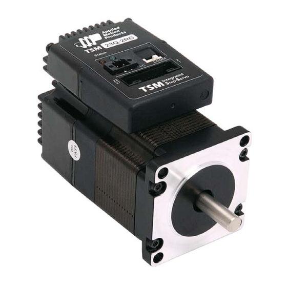
- Page 1 TSM23S/Q Integrated Step-Servo Motor Hardware Manual Rev. A...
-
Page 2: Table Of Contents
3.2.1 Connecting to the PC using RS-232 ............14 3.2.2 Connecting to a Host using RS-485 .............15 3.3 Inputs and Outputs ................17 3.3.1 Connector Pin Diagram ................17 3.3.2 STEP & DIR Digital Inputs ..............18 3.3.3 X3/X4/X5/X6 Digital Input ..............19 3.3.4 X7/X8 Digital Input ................20 3.3.5 AIN Input ....................20 3.3.6 Programmable Output Y1/Y2/Y3 ............21... - Page 3 TSM23S/Q Hardware Manual Communications Model RS-232 RS-485 Modbus/RTU TSM23S-2AG TSM23S-2RG TSM23S-3AG TSM23S-3RG TSM23S-4AG TSM23S-4RG TSM23Q-2AG TSM23Q-2RG TSM23Q-3AG TSM23Q-3RG TSM23Q-4AG TSM23Q-4RG Rev. A 920-0081...
-
Page 4: Introduction
* Digital input Control Velocity * Analog velocity * SCL Commanded Velocity (Jogging) Position Control * Digital Signal type Step & Direction CW & CCW pulse A/B Quadrature * Analog Position * Serial Commanded Position Q Programming(Q Verision only) * Stand alone operation •... -
Page 5: Block Diagram
TSM23S/Q Hardware Manual 1.2 Block Diagram TSM23S/Q Block Diagram 12 - 70 VDC External 5 Volt DC Power Supply Power Supply RS-232 RXD,+5V,TXD,GND,GND RS-232 or RS-485 RS-485 3.3VDC RX+,RX-,TX+,TX-,GND Internal Voltage Logic Temp Supply Detect +5VDC (100mA max) MOSFET motor Power Amplifier Driver... -
Page 6: Safety Instructions
TSM23S/Q Hardware Manual 1.3 Safety Instructions Only qualified personnel should transport, assemble, install, operate, or maintain this equipment. Properly qualified personnel are persons who are familiar with the transport, assembly, installation, operation, and maintenance of motors, and who meet the appropriate qualifications for their jobs. To minimize the risk of potential safety problems, all applicable local and national codes regulating the installation and operation of equipment should be followed. -
Page 7: Getting Started
TSM23S/Q Hardware Manual 2 Getting Started The following items are needed: • a 12 - 70 Volt DC power supply, see the section below entitled “Choosing a Power Supply” for help in choosing the right one • a small flat blade screwdriver for tightening the connectors (included) •... -
Page 8: Choosing A Power Supply
TSM23S/Q Hardware Manual 2.3 Choosing a Power Supply The main considerations when choosing a power supply are the voltage and current requirements for the application. 2.3.1 Voltage The TSM23S/Q is designed to give optimum performance between 24 and 48 Volts DC. Choosing the voltage depends on the performance needed and motor/drive heating that is acceptable and/ or does not cause a drive over-temperature. -
Page 9: Current
TSM23S/Q Hardware Manual 2.3.3 Current The maximum supply currents required by the TSM23S/Q are shown in the charts below at different power supply voltage inputs. The TSM23S/Q power supply current is lower than the winding currents because it uses switching amplifiers to convert a high voltage and low current into lower voltage and higher current. - Page 10 TSM23S/Q Hardware Manual □ □ TSM23 G 70V Power Torque Continuous Boost Supply Current Full Load No Load Speed(RPS) □ □ TSM23 G 24V Power Torque Continuous Boost Supply Current Full Load No Load Speed(RPS) □ □ TSM23 G 48V Power Torque Continuous Boost...
- Page 11 TSM23S/Q Hardware Manual □ □ TSM23 G 70V Power Torque Continuous Boost Supply Current Full Load No Load Speed(RPS) □ □ TSM23 G 24V Power Torque Continuous Boost Supply Current Full Load No Load Speed(RPS) □ □ TSM23 G 48V Power Torque Continuous Boost...
- Page 12 TSM23S/Q Hardware Manual □ □ TSM23 G 70V Power Torque Continuous Boost Supply Current Full Load No Load Speed(RPS) Rev. A 920-0081...
-
Page 13: Installation/Connections
“+” terminal that is not user replaceable. If a user serviceable fuse is desired, install a 6.3 amp fast acting fuse in line with the “+” power supply lead. Be careful not to reverse the wires. Reversing the connection may open the internal fuse on the drive and void the warranty. -
Page 14: Connecting The Tsm23S/Q Communications
TSM23S/Q Hardware Manual 3.2 Connecting the TSM23S/Q Communications □ The TSM23S/Q is available with two types of serial communications, RS-232 (TSM23S/Q - □ or RS-485 (TSM23S/Q - RG). Each type requires a different hardware connection for interface to a PC or other Host system. The RS-232 version comes with a cable that will provide the interface to an RS-232 port through a DB9 style connector. -
Page 15: Connecting To A Host Using Rs-485
TSM23S/Q Hardware Manual 3.2.2 Connecting to a Host using RS-485 RS-485 communication allows connection of more than one drive to a single host PC, PLC, HMI or other computer. It also allows the communication cable to be long (more than 300 meters or 1000 feet). - Page 16 The numerals 0..9 or the special characters ! “ # $ % & ‘ ( ) * + , - . / : ; < = > ? @ may be used as addresses. Make sure each drive on the network has a unique address.
-
Page 17: Inputs And Outputs
3.3 Inputs and Outputs The TSM23S/Q has three types of inputs: • High speed digital inputs for step & direction commands or encoder following, 5 to 24 volt logic • Low speed digital input for other signals, 5 to 24 volt logic •... -
Page 18: Step & Dir Digital Inputs
“following” applications. Or you can use these inputs with Wait Input(WI), Feed to Sensor(FS), Seek Home(SH) and other SCL or Q commands. The diagrams below show how to connect the STEP & DIR Inputs to various commonly used devices. -
Page 19: X3/X4/X5/X6 Digital Input
TSM23S/Q Hardware Manual 3.3.3 X3/X4/X5/X6 Digital Input While the STEP and DIR inputs are designed for high-speed digital input operation, the X3/X4/ X5/X6 input are designed for low speed digital input operation between 5 and 24 volts optically Isolated Single-ended input. They can be used with sourcing or sinking signals, 5 to 24 volts. This allows connection to PLCs, sensors, relays and mechanical switches. -
Page 20: X7/X8 Digital Input
TSM23S/Q Hardware Manual 3.3.4 X7/X8 Digital Input The X7/X8 input are designed for low speed digital input operation between 5 and 24 volts optically Isolated differential input. They are normally used for end of travel limit switches. The diagrams below show how to connect the X7/X8 Inputs to various commonly used devices X7/X8+ 5 - 24 volt DC... -
Page 21: Programmable Output Y1/Y2/Y3
TSM23S/Q Hardware Manual 3.3.6 Programmable Output Y1/Y2/Y3 The TSM23S/Q drives feature three optically isolated digital outputs (Y1 to Y3). Y1, Y2 and Y3 share a common terminal YCOM. • Y1 can be set to signal a fault condition. • Y2 can be set to indicate whether the motor is in position(dynamic). •... -
Page 22: Programmable Output Y4
TSM23S/Q Hardware Manual 3.3.7 Programmable Output Y4 TSM23S/Q drives feature one optically isolated digital output Y4. The Y4+(collector) and Y4- (emitter) terminals of the transistor are available at the connector. This allow the output to be configured for current sourcing or sinking. Y4 can be set to provide an output frequency proportional to motor speed (tach signal) or to provide a timing output (50 pulses/rev) or to indicate whether the motor is in position(static) Diagrams of various connection types follow. -
Page 23: Troubleshooting
TSM23S/Q Hardware Manual 4 Troubleshooting 4.1 LED Error Codes The TSM23S/Q uses red and green LEDs to indicate status. When the motor is enabled, the green LED flashes slowly. When the green LED is solid, the motor is disabled. Errors are indicated by combinations of red and green flashes as shown below. -
Page 24: Reference Materials
TSM23S/Q Hardware Manual 5 Reference Materials 5.1 Torque-Speed Curves Note: all torque curves were measured at 20,000 steps/rev. Note: 5 amp rating is continuous, 7.5 amp rating is boost □ □ Continuous TSM23 Boost Speed(rps) □ □ Continuous TSM23 Boost Speed(rps) □... -
Page 25: Mechanical Outlines
TSM23S/Q Hardware Manual 5.2 Mechanical Outlines L±1 56.4 Max. 47.14 4-Ø5.1 50.9 Unit:mm Model Length (L) Length (M) TSM23S/Q-2□G 95.6 24.6 TSM23S/Q-3□G 117.6 46.6 TSM23S/Q-4□G 120.6 49.9 Rev. A 920-0081... -
Page 26: Technical Specifications
Filters Configurations are saved in FLASH memory on-board the DSP Non-Volatile Storage TSM23S: Step & direction, CW/CCW pulse, A/B quadrature pulse, velocity (oscillator, Modes of Operation joystick), streaming commands(SCL) TSM23Q: All TSM23S modes of operation plus stored Q program execution... -
Page 27: Scl Command Reference
TSM23S/Q Hardware Manual 5.4 SCL Command Reference The Serial Command Language (SCL) was developed to give users a simple way to control a motor drive via a serial port. This eliminates the need for separate motion controllers or indexers to supply Pulse and Direction signals to the drive. It also provides an easy way to interface to a variety of other industrial devices such as PLCs and HMIs, which often have standard or optional serial ports for communicating to other devices. - Page 28 TSM23S/Q Hardware Manual Some SCL commands transfer data to the drive for immediate or later use. These data values are stored in data registers and remain there until new commands change the values or power is removed from the drive. Some data registers in a drive are Read-Only and contain predefined information about the drive which can also be read through SCL commands.
-
Page 29: Contacting Applied Motion Products
TSM23S/Q Hardware Manual 6 Contacting Applied Motion Products 404 Westridge Dr. Watsonville, CA 95076, USA 1-800-525-1609 Tel (831) 761-6555 Fax (831) 761-6544 www.applied-motion.com Rev. A 920-0081...
Need help?
Do you have a question about the TSM23S series and is the answer not in the manual?
Questions and answers