
Subscribe to Our Youtube Channel
Related Manuals for Clearfield FieldSmart FAC 5400

Summary of Contents for Clearfield FieldSmart FAC 5400
- Page 1 FieldSmart Fiber Active Cabinet (FAC) 5400 ® Installation Manual ______________________________________________________ Manual 020422 REV A - Jan 2019...
-
Page 2: Table Of Contents
Chapter 4: Installing the Cabinet Unpacking the Cabinet Operating Cabinet Doors Preparing the Cabinet for Installation Installing the Cabinet on a Concrete Pad Replacing the Lifting Eye Bolts Proprietary Information: Not for use or disclosure except by written agreement with Clearfield. - Page 3 FieldSmart Fiber Active Cabinet (FAC) 5400 ® Installation Manual __________________________________________________________ Chapter 5: Installing Power Installing the Cabinet Ground Connection Installing AC Power (220-240 VAC) Installing AC Power (110-120 VAC) Chapter 6: Installing and Splicing Outside Plant Cables Installing Metallic Cables Installing Metallic Outside Plant Cables Splicing Metallic Cables Installing 5-Pin Protection Modules...
- Page 4 Rack Space for Additional Equipment Valere Rectifier Alarm Matrix Valere Rectifier Setpoints Programming the Valere Shelf Controller Rectifier Module Usage Guidelines Wiring Diagrams Standard Warranty Proprietary Notice Technical Support Proprietary Information: Not for use or disclosure except by written agreement with Clearfield.
-
Page 5: About This Guide
About This Guide Purpose This document provides a general installation practice for the Clearfield FAC 5400 outdoor cabinet. This document also provides a general description of the cabinet and its subsystems, and guidance for planning, site preparation, power instal- lation, splicing to the outside plant, component installation and expansion, and cabinet maintenance. -
Page 6: Chapter 1: Fiber Active Cabinet 5400 Product Overview
® Installation Manual _________________________________________________________ Chapter 1: Fiber Active Cabinet 5400 Product Overview This chapter provides a general description of the Clearfield FAC 5400 outdoor cabinet, including its standard features and options. Topics Covered This chapter covers the following topics: •... -
Page 7: Cabinet Description
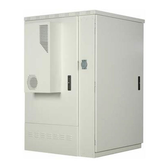
__________________________________________________________ Cabinet Description The Clearfield FAC 5400 cabinet is an environmentally-controlled outdoor enclosure designed to house and protect network electronics equipment. Use the FAC 5400 to provide network services from a remote location, extending the service area beyond the reach of the carrier Central Office. -
Page 8: Cabinet Features
Optional Valere compact DC power system (with distribution) • Redundant DC supplies to equipment (A and B) • Low voltage DC disconnect (-42V) • Up to 340Ah battery reserve capacity (NSB 170FT) Proprietary Information: Not for use or disclosure except by written agreement with Clearfield. -
Page 9: Cabinet Options
Installation Manual __________________________________________________________ Cabinet Options Common options for the FAC 5400 cabinet include: Enclosure Mounting • Site-cast concrete pad using Clearfield template • Pre-cast concrete pad Power • 220/240 VAC input, reconfigurable for 110/120 VAC (requires 20A rectifier modules) •... -
Page 10: Cabinet Dimensions And Weights
The approximate shipping weights of the FAC 5400 cabinet are shown below. Configuration Weight (SAE) Weight (Metric) 960 lines (standard) 1271 lb 577 kg 960 lines (cross-connect) 1435 lb 651 kg Proprietary Information: Not for use or disclosure except by written agreement with Clearfield. -
Page 11: Cabinet Compartments
FieldSmart Fiber Active Cabinet (FAC) 5400 ® Installation Manual __________________________________________________________ Cabinet Compartments Views of the FAC 5400 cabinet compartments follow. Front Compartment The front compartment provides 47 inches of vertical rack space (27 RU). The front compartment typically houses an op- tional Valere power system, leaving 21 RU of rack space for additional equipment. - Page 12 The swing frame rack design allows for easy access to the backside of mounted equipment. FAC 5400 Rear FAC 5400 Rear (cross-connect) Proprietary Information: Not for use or disclosure except by written agreement with Clearfield.
- Page 13 FieldSmart Fiber Active Cabinet (FAC) 5400 ® Installation Manual __________________________________________________________ Splice Compartment The splice compartment provides 67 inches of vertical rack space (38 RU). The splice compartment houses the AC load center and main ground bar and provides the cable entry locations. The splice compartment also typically houses the cop- per line protection, which consists of up to four rack-mounted protection frames, each holding up to six modular 50-pair protection blocks.
-
Page 14: Chapter 2: Installation Considerations
This chapter covers the following topics: • Installation process overview • Installation guidelines • Space requirements • General safety recommendations • Installation kit contents • User-supplied items • Cabling requirements Proprietary Information: Not for use or disclosure except by written agreement with Clearfield. -
Page 15: Installation Process Overview
FieldSmart Fiber Active Cabinet (FAC) 5400 ® Installation Manual __________________________________________________________ Installation Process Overview The cabinet installation process involves the following high-level steps: Direct: 763.476.6866 • National: 800.422.2537 • www.SeeClearfield.com • techsupport@clfd.net Manual 020422 REV A - Jan 2019... -
Page 16: Installation Guidelines
Conversely, wind exposure improves thermal conditions in a cabinet, so locations that do not block wind are desirable. Proprietary Information: Not for use or disclosure except by written agreement with Clearfield. -
Page 17: Space Requirements
FieldSmart Fiber Active Cabinet (FAC) 5400 ® Installation Manual __________________________________________________________ 2. Accessibility requirements: • Electrical access. Cabinets must have access to commercial AC power. Verify the availability of AC service at potential cabinet locations. • Easement size. Select a location with an easement that provides enough space to walk around the perimeter of the cabinet with its doors open. -
Page 18: General Safety Recommendations
CAUTION! Batteries contain a stored charge. Handle batteries with care. ESD ALERT! Beware of electrostatic discharge. Follow standard ESD precautions. Always wear a grounded ESD wristband to avoid damaging the electronic equipment. Proprietary Information: Not for use or disclosure except by written agreement with Clearfield. -
Page 19: Installation Kit
Installation Manual __________________________________________________________ Installation Kit Clearfield supplies an installation kit with the cabinet that includes materials required for installation. The installation kit contents are listed below. Check to verify that your kit contains all of the listed items. Item Description Telco hex key, 5/16”... -
Page 20: User-Supplied Items
Four (4) wire rope slings, minimum 6 foot length each • Five (5) connecting links or lifting hooks • Four (4) shims • Digital multi-meter • Optical power meter • Digital multi-function test set Proprietary Information: Not for use or disclosure except by written agreement with Clearfield. -
Page 21: Cabling Requirements
FieldSmart Fiber Active Cabinet (FAC) 5400 ® Installation Manual __________________________________________________________ Cabling Requirements Cables supplied to the cabinet must meet the following minimum requirements. Function Facility Requirements Power 2 AWG solid bare copper wire (to earth ground circuit); Ground Copper terminates to ground bar with 2-hole compression lug Copper 6 to 8 AWG;... -
Page 22: Chapter 3: Preparing The Installation Site
For pad-mounted configurations, you can construct a concrete pad using the Clearfield cast-in-place template, or you can purchase a pre-cast concrete pad from a third-party supplier. For all mounting configurations, Clearfield requires installation of an earth ground circuit at the installation site to provide lightning protection. -
Page 23: Installing A Ground Circuit
Installing a Ground Circuit Clearfield requires installing an earth ground circuit (earth electrode) at the installation site to provide protection from electric shock for equipment and personnel. The ground circuit may consist of a simple copper rod driven into the earth or a com- plex system of buried rods and wires. - Page 24 The ground wire should enter the cabinet separated from power or copper transmission cables. Never bundle the ground wire together with other copper cables. • Connect the ground wire to the main ground bar. Follow local code to satisfy additional requirements, if applicable. Proprietary Information: Not for use or disclosure except by written agreement with Clearfield.
-
Page 25: Constructing A Concrete Pad
Construct a concrete foundation pad for the cabinet at the installation site. Pad construction requires excavating the site, trenching cable conduit, constructing a form, and casting concrete. Use the Clearfield-supplied cast-in-place template to provide exact locations for the mounting studs that anchor the cabinet to the pad and to provide the cable conduit locations. - Page 26 FieldSmart Fiber Active Cabinet (FAC) 5400 ® Installation Manual _________________________________________________________ Pad Drawings Use the following drawings for reference during pad construction. Pad Size Proprietary Information: Not for use or disclosure except by written agreement with Clearfield.
- Page 27 Conduit for outside plant cable. b. Earth ground wire (preferred location for direct connection to cabinet ground bar). c. Conduit for AC cable. Use the Clearfield cast-in-place template to provide precise conduit orientation. Conduit Locations Direct: 763.476.6866 • National: 800.422.2537 • www.SeeClearfield.com • techsupport@clfd.net...
-
Page 28: Assembling The Cast-In-Place Template
Align the Left bracket screw holes with the counterpart holes on the Front and Rear brackets. Step 4: Align the Splice bracket screw holes with the counterpart holes on the Front and Rear brackets. Proprietary Information: Not for use or disclosure except by written agreement with Clearfield. - Page 29 FieldSmart Fiber Active Cabinet (FAC) 5400 ® Installation Manual __________________________________________________________ Step 5: Install the eight supplied screws (with washers) into the threaded screw holes to connect the brackets together. Use two screws at each junction point as shown. Step 6: Tighten all screws to complete the template assembly.
-
Page 30: Preparing The Site
Step 3: Place and tie rebar inside the form elevated above the gravel. Step 4: Place the Clearfield cast-in-place template into the form, guiding the cable conduits through the conduit entry ducts in the template. Step 5: Align the template mounting brackets flush with the top of the form, then nail the template to the form to secure it in place. -
Page 31: Casting The Pad
FieldSmart Fiber Active Cabinet (FAC) 5400 ® Installation Manual __________________________________________________________ Casting the Pad Cast the concrete foundation pad as described below. Adapt the instructions as needed for local requirements, practices, or conditions. To cast the concrete pad Step 1: Prepare the concrete mix. Be sure to mix enough concrete to cast the entire pad in a single pour. Note: To avoid structural weakening, do not cast a pad from multiple concrete pours. -
Page 32: Installing A Pre-Cast Concrete Pad
Use 2-inch maximum conduit for AC cable. See drawing below for entry location. • Include pull cords in all cable conduits. Refer to the pad manufacturer's instructions for additional guidelines. Proprietary Information: Not for use or disclosure except by written agreement with Clearfield. - Page 33 FieldSmart Fiber Active Cabinet (FAC) 5400 ® Installation Manual __________________________________________________________ Pad Drawings Use the following drawings for reference during site preparation. Actual pad dimensions may vary by manufacturer. Refer to the manufacturer's documentation for more information. Typical Pad Size Direct: 763.476.6866 • National: 800.422.2537 • www.SeeClearfield.com • techsupport@clfd.net Manual 020422 REV A - Jan 2019...
- Page 34 Conduit for outside plant cable. b. Earth ground wire (preferred location for direct connec- tion to cabinet ground bar). c. Conduit for AC cable. Conduit Locations Proprietary Information: Not for use or disclosure except by written agreement with Clearfield.
-
Page 35: Preparing The Site
FieldSmart Fiber Active Cabinet (FAC) 5400 ® Installation Manual __________________________________________________________ Preparing the Site Prepare the site for installation of a pre-cast pad. Some pads may require custom preparations. Refer to the manufacturer's instructions for more information. A general practice is described below for reference. Adapt the instructions as needed for local requirements, practices, or conditions. -
Page 36: Installing A Pre-Cast Pad
Step 6: Backfill and grade around the pad perimeter with soil to secure the pad in place. Step 7: Verify that the pad remains level. Adjust as required. Proprietary Information: Not for use or disclosure except by written agreement with Clearfield. -
Page 37: Chapter 4: Installing The Cabinet
® Installation Manual __________________________________________________________ Chapter 4: Installing the Cabinet This chapter describes how to install the Clearfield FAC 5400 cabinet onto its permanent mounting location. Topics Covered This chapter covers the following topics: • Unpacking the cabinet from its shipping crate. -
Page 38: Unpacking The Cabinet
Do not remove the cabinet from the pallet until after it has been delivered to the installation site. However, you can remove the cardboard crating to inspect the cabinet at the staging area, if required. Clearfield recommends keeping the protective packaging in place for transportation. -
Page 39: Operating Cabinet Doors
Open and close the compartment doors using the Clearfield-supplied telco hex key. Each cabinet door is also equipped with an alarm switch that monitors the position of the door. When a door opens on a powered cabinet, an intrusion alarm reports through the equipment. - Page 40 Some force may be required. Step 3: Insert the bolts (removed previously) through the matching holes in the door and cabinet and tighten using a 7/16-inch nut driver. Proprietary Information: Not for use or disclosure except by written agreement with Clearfield.
-
Page 41: Preparing The Cabinet For Installation
Complete the following pre-installation preparations before installing the cabinet. ALERT! Isolation mat usage is mandatory for pad installations. Failure to use the isolation mat can accelerate cabinet corrosion and may void the Clearfield cabinet warranty. To prepare the cabinet for installation Step 1: Open the front, rear, and splice compartment doors. -
Page 42: Installing The Cabinet On A Concrete Pad
Use appropriately rated connecting links or lifting hooks. Clearfield recommends using at least three people to install the cabinet: one to operate the crane or derrick, one to guide the cabinet laterally as it lowers, and one to spot-check alignment of the mounting anchors/holes and the conduits/entry boxes as the cabinet lowers. - Page 43 FieldSmart Fiber Active Cabinet (FAC) 5400 ® Installation Manual __________________________________________________________ Step 5: Lift the cabinet approximately 12 inches above the ground and position it directly above the foundation pad. Step 6: Slowly lower the cabinet onto the pad, keeping the mounting holes in the cabinet base aligned with the anchor studs (or anchor holes) in the pad.
- Page 44 Verify that all cabinet doors open and close freely. If necessary, use shims to level the cabinet. Step 11: Apply silicone caulking to the bottom perimeter of the cabinet. Proprietary Information: Not for use or disclosure except by written agreement with Clearfield.
-
Page 45: Replacing The Lifting Eye Bolts
Using a screwdriver, unscrew and remove a lifting eyebolt from the top of the cabinet. Step 2: Using the Clearfield-supplied telco hex key, install a button-head Allen bolt into the vacant bolt hole. Step 3: Repeat Steps 1 and 2 to replace each additional lifting eyebolt on the cabinet roof, one at a time. -
Page 46: Chapter 5: Installing Power
This chapter covers the following topics: • Installing the cabinet ground connection. • Installing the AC power supply (220–240 VAC standard). • Installing the AC power supply (110–120 VAC option). Proprietary Information: Not for use or disclosure except by written agreement with Clearfield. -
Page 47: Installing The Cabinet Ground Connection
FieldSmart Fiber Active Cabinet (FAC) 5400 ® Installation Manual __________________________________________________________ Installing the Cabinet Ground Connection The cabinet's connection to the earth ground circuit must be in place before you install power to the cabinet. To install the cabinet ground connection Step 1: Open the splice compartment door. -
Page 48: Installing Ac Power (220-240 Vac)
Step 7: Remove the Main Service Disconnect breaker from the load center housing to ease wire termination. Pull the breaker straight out to disengage it from the assembly. Proprietary Information: Not for use or disclosure except by written agreement with Clearfield. -
Page 49: Installing Ac Power (110-120 Vac)
FieldSmart Fiber Active Cabinet (FAC) 5400 ® Installation Manual __________________________________________________________ Step 8: Connect the AC wiring as follows: • Connect the green (ground) lead to the ground bus bar. • Connect the white (neutral) lead to the neutral bar. • Connect the black L1 lead to the left side of the Main Service Disconnect breaker. - Page 50 Dress and secure the AC cable, providing adequate strain relief. Step 9: Replace the AC duct cover (two panels) and the left cover panel on the AC load center. Proprietary Information: Not for use or disclosure except by written agreement with Clearfield.
-
Page 51: Chapter 6: Installing And Splicing Outside Plant Cables
FieldSmart Fiber Active Cabinet (FAC) 5400 ® Installation Manual __________________________________________________________ Chapter 6: Installing and Splicing Outside Plant Cables This chapter describes how to install and splice outside plant cables into the cabinet, including metallic plant (copper twisted pairs for subscriber drops and/or transport) and fiber plant (fiber-optic cables for transport and/or PON subscriber drops). Topics Covered This chapter covers the following topics: •... -
Page 52: Installing Metallic Cables
Install a B-bond clamp onto the cut end of the OSP cable's outer sheath. Wrap the connection with electrical tape. b. Attach a #6 AWG bond strap to the B-bond clamp. Proprietary Information: Not for use or disclosure except by written agreement with Clearfield. - Page 53 FieldSmart Fiber Active Cabinet (FAC) 5400 ® Installation Manual __________________________________________________________ c. Terminate the other end of the bond strap to the main ground bar at the bottom of the splice compartment. Step 4: Secure the OSP cable to the rack or tie bars with cable ties. Step 5: Remove the core wrap from around the bundled copper pairs, down to 18 inches above the cut end of the outer sheath, then install binder group identification labels on each 25-pair group.
-
Page 54: Splicing Metallic Cables
Repeat Steps 2 through 5 for each remaining OSP cable. Step 7: Dress and secure the spliced cables to the rack or tie bars with cable ties. Proprietary Information: Not for use or disclosure except by written agreement with Clearfield. -
Page 55: Installing 5-Pin Protection Modules
FieldSmart Fiber Active Cabinet (FAC) 5400 ® Installation Manual __________________________________________________________ Installing 5-Pin Protection Modules To complete the wiring connection between the metallic outside plant cables and cabinet equipment cables, you must install 5-pin protection modules into the protection blocks to protect the copper lines from electrical surges. Each protection block protects 48 pairs with each 5-pin position on the block protecting one wire pair (one 2-wire circuit or half of a 4-wire circuit). -
Page 56: Installing Fiber Cables
If splicing shall be performed at a later date, make sure the OSP cables fit inside the splice compartment with the door closed. Take care to not violate the cable bend radius requirements. Proprietary Information: Not for use or disclosure except by written agreement with Clearfield. - Page 57 FieldSmart Fiber Active Cabinet (FAC) 5400 ® Installation Manual __________________________________________________________ The following steps are general guidelines only. Follow local practice where applicable. To prepare outside plant cables for splicing Step 1: Untie the ropes or cut the cable ties temporarily securing the OSP cables inside the splice compartment. Step 2: Strip off approximately six feet of the cable's outer sheath to expose the core tubing.
-
Page 58: Splicing Fiber Cables
Both the pigtail and jumper splicing methods typically use fiber splice trays to hold the individual fiber splices. Clearfield offers field-installed splice trays with fusion, mechanical, and heat shrink splicing options. Each fiber splice tray can hold up to 12 fiber splices. -
Page 59: Routing And Terminating Fibers
No intermediate patch panel is typically used. Route and terminate fibers per your application requirements and local practice. Clearfield offers field-installed fiber distri- bution systems that mount in an available 23-inch rack space. Options include a 1 RU fiber distribution panel with 12 or 24 positions, or a 6 RU fiber distribution cassette holder that holds up to six cassettes, each with 12 positions. -
Page 60: Sealing Cable Entry Locations
Follow the manufacturer's instructions to apply the sealant. CAUTION! Check to ensure that all gaps are completely sealed. Gaps allow penetration of moisture, insects, rodents, and other contaminants that could damage equipment. Proprietary Information: Not for use or disclosure except by written agreement with Clearfield. -
Page 61: Chapter 7: Turning Up The Cabinet Power System
FieldSmart Fiber Active Cabinet (FAC) 5400 ® Installation Manual __________________________________________________________ Chapter 7: Turning Up the Cabinet Power System This chapter describes how to turn up and test the cabinet power system, including checking the AC power supply voltage, installing rectifier modules into the optional Valere power shelf, installing batteries for reserve power, and turning up and testing the DC power system. -
Page 62: Checking The Ground Connection
Remove the left and right cover panels from the AC load center. b. Switch the 60A Main Service Disconnect breaker to ON. c. Switch the 60A Main breaker to ON. Proprietary Information: Not for use or disclosure except by written agreement with Clearfield. - Page 63 FieldSmart Fiber Active Cabinet (FAC) 5400 ® Installation Manual __________________________________________________________ Step 3: Using a volt meter, test between the L1 and neutral busses: a. Place one lead on the L1 buss. b. Place the other lead on the neutral buss. c.
- Page 64 Note: Do not switch on the Rectifier A and Rectifier B breakers at this time. Step 6: Re-attach the left and right cover panels on the AC load center. Proprietary Information: Not for use or disclosure except by written agreement with Clearfield.
-
Page 65: Installing Rectifier Modules Into The Optional Valere Power Shelf
FieldSmart Fiber Active Cabinet (FAC) 5400 ® Installation Manual __________________________________________________________ Installing Rectifier Modules into the optional Valere Power Shelf The FAC 5400 cabinet can be outfitted with an optional Valere compact power system to generate and distribute -48 VDC bulk power. The Valere power system consists of a 19-inch G-series power shelf and a 23-inch DC distribution shelf. The Valere power shelf supports up to four rectifier modules (30A or 20A options). - Page 66 Push the ejector lever closed to secure the module in place. Step 6: Repeat Steps 1–5 to install additional rectifier modules. Note: Refer to the Valere Compact DC Power System Installation and Maintenance manual for more information. Proprietary Information: Not for use or disclosure except by written agreement with Clearfield.
-
Page 67: Installing Batteries
FieldSmart Fiber Active Cabinet (FAC) 5400 ® Installation Manual __________________________________________________________ Installing Batteries The FAC 5400 cabinet can house up to two strings of front terminal batteries (four batteries per string). See Supported Batteries for a list of supported battery types. WARNING! Electrical hazard. - Page 68 Step 6: If you are using three battery strings, install the #10 AWG white jumper cable between the two middle batteries of String 3 as shown below. Proprietary Information: Not for use or disclosure except by written agreement with Clearfield.
- Page 69 FieldSmart Fiber Active Cabinet (FAC) 5400 ® Installation Manual __________________________________________________________ Step 7: For each battery string, connect the battery power cables as follows: a. Remove the protective rubber caps from the cable ring lugs. b. Attach the black cable to the positive (+) terminal post at the positive end of the string. c.
-
Page 70: Turning Up And Testing The Dc Power System
(if internal temperature is high enough). Step 6: At the DC distribution panel, switch the 40A battery breakers ON to charge the batteries. Proprietary Information: Not for use or disclosure except by written agreement with Clearfield. - Page 71 FieldSmart Fiber Active Cabinet (FAC) 5400 ® Installation Manual __________________________________________________________ Testing Batteries If the batteries are not fully charged, perform this procedure after charging the batteries. WARNING! Electrical hazard. Only a qualified technician should perform these procedures. To test the batteries Step 1: At the DC distribution panel, verify that the battery breakers are ON.
-
Page 72: Chapter 8: Installing Equipment And Adding Capacity
Note: Before installing any powered equipment on the rear equipment rack, you must first remove the air plenum cover to enable proper air circulation and cooling to the rear rack. See Removing the Air Plenum Cover for instruc- tions. Proprietary Information: Not for use or disclosure except by written agreement with Clearfield. -
Page 73: Installing A Protection Mounting Frame
FieldSmart Fiber Active Cabinet (FAC) 5400 ® Installation Manual __________________________________________________________ Installing a Protection Mounting Frame The modular design of the cabinet's copper line protection system allows you to incrementally expand line capacity. Pro- tection blocks are housed in a mounting frame that installs on a 23-inch rack. Each mounting frame holds up to six 50-pair protection blocks. -
Page 74: Installing A Protection Block
Pull down the spring-loaded plunger latch at the top of the protection block. While holding the plunger down, rotate the block into the mounting frame. Release the plunger latch to secure it in the frame. Proprietary Information: Not for use or disclosure except by written agreement with Clearfield. - Page 75 FieldSmart Fiber Active Cabinet (FAC) 5400 ® Installation Manual __________________________________________________________ c. Fasten the protection block to the mounting frame using two supplied screws. Note: The screws provide a critical ground path through the mounting frame to the cabinet's main ground bar. Step 6: On the mounting frame, turn the two knobs counter-clockwise (to the open position), then pull the frame for- ward to access the area behind the protection blocks.
-
Page 76: Installing A Battery Heater
Installing a Battery Heater For colder climates, Clearfield recommends using an optional battery heater to prevent batteries from freezing and to prolong battery life. One battery heater supports the maximum of three battery strings. The battery heater is controlled by a thermostat set for the following operation: •... -
Page 77: Installing An Ac Meter
FieldSmart Fiber Active Cabinet (FAC) 5400 ® Installation Manual __________________________________________________________ Installing an AC Meter You can mount a commercial AC power meter directly to the exterior of the cabinet if required. The suggested meter mount- ing location is on the front of the cabinet above the generator connector housing. To install a meter in this location, you must cut a hole in the cabinet wall. -
Page 78: Installing A Generator Connector
Note: Do not discard the four mounting nuts. The nuts will be reused to install the generator connector. b. At the exterior front of the cabinet, pull the blank plate away from the cabinet wall to expose the connector mounting fixture. Proprietary Information: Not for use or disclosure except by written agreement with Clearfield. - Page 79 FieldSmart Fiber Active Cabinet (FAC) 5400 ® Installation Manual __________________________________________________________ To install a generator connector Step 1: Unpack the generator connector from the shipping packaging. Step 2: For 30 Amp generator connectors, install an adapter plate onto the wall mounting fixture as follows: a.
- Page 80 Replace the AC duct cover (two panels) and the AC load center cover panel. Step 6: At the AC load center, switch all breakers to ON. Step 7: At the local power transfer switch, restore AC power to the cabinet. Proprietary Information: Not for use or disclosure except by written agreement with Clearfield.
-
Page 81: Chapter 9: Cabinet Maintenance
FieldSmart Fiber Active Cabinet (FAC) 5400 ® Installation Manual __________________________________________________________ Chapter 9: Cabinet Maintenance This chapter describes how to perform cabinet maintenance, including routine maintenance and corrective maintenance to replace worn or failed parts and equipment. Topics Covered This chapter covers the following topics: •... -
Page 82: Routine Maintenance
Battery maintenance does not impact cabinet service, provided that an AC power failure does not occur during the main- tenance process. Clearfield recommends connecting an external generator to the cabinet while performing battery mainte- nance to ensure service continuity in the event of an AC outage. -
Page 83: Checking Electrical Components
FieldSmart Fiber Active Cabinet (FAC) 5400 ® Installation Manual __________________________________________________________ Step 4: Visually inspect each battery for defects such as: • Fractured housing or other physical damage • Leakage • Bulging Note: Replace any battery that displays a defect. See Replacing Batteries for instructions. Step 5: Perform the following maintenance tasks: a. -
Page 84: Checking Cabinet Surfaces
Clearfield support for assistance with a resolution. • Repair damage to the paint using touch-up paint available from Clearfield after cleaning the surface and removing rust. • Inspect all gaskets around the doors and the roof to ensure a tight secure fit. -
Page 85: Replacing Parts And Equipment
A heat exchanger fails or becomes damaged. You can replace cabinet doors in the field without impacting service. Order replacement doors from Clearfield. CAUTION! Cabinet doors are heavy. Handle with care to avoid personal injury or damage to the door. Two people are required to perform this task. -
Page 86: Replacing Ac Breakers
At the AC load center, switch the Main Service Disconnect and Main main circuit breakers to OFF. Step 3: Remove the cover panel from the AC load center. Step 4: Remove any wires from the defective circuit breaker. Proprietary Information: Not for use or disclosure except by written agreement with Clearfield. -
Page 87: Replacing Dc Breakers And Fuses
FieldSmart Fiber Active Cabinet (FAC) 5400 ® Installation Manual __________________________________________________________ Step 5: Remove the defective breaker from the load center and replace it with a new breaker of the same type and rating. Step 6: Reconnect all wiring to the new circuit breaker. Step 7: Replace the AC load center cover panel. - Page 88 Replace the fuse with a fuse of the same rating and type. Step 4: If the fuse fails again do not replace it. Troubleshoot to find the cause of the failure. Proprietary Information: Not for use or disclosure except by written agreement with Clearfield.
-
Page 89: Replacing Rectifier Modules (For Optional Valere Rectifier)
Valere shelf. Note: If the Valere shelf is not equipped with a redundant rectifier module, and the load is heavy, Clearfield recommends temporarily installing an additional module into the shelf to carry the load while you replace the failed module. - Page 90 Basic Menu level. Note: For detailed instructions on controller functionality, including how to program the controller module, see the Valere Compact DC Power System Installation and Maintenance manual. Proprietary Information: Not for use or disclosure except by written agreement with Clearfield.
-
Page 91: Replacing Batteries
Replacing batteries does not impact cabinet service, provided that an AC power failure does not occur during the replacement process. Clearfield recommends connecting an external generator to the cabinet while performing battery maintenance to ensure service continuity in the event of an AC outage. -
Page 92: Replacing A Battery Heater
Install the new battery heater into the battery compartment and connect it power cord to the AC outlet. See Installing a Battery Heater for instructions. Step 6: Reload and reconnect batteries. See Installing Batteries for instructions. Proprietary Information: Not for use or disclosure except by written agreement with Clearfield. -
Page 93: Appendix A: Reference Information
FieldSmart Fiber Active Cabinet (FAC) 5400 ® Installation Manual __________________________________________________________ Appendix A: Reference Information This appendix provides general reference information about the FAC 5400 cabinet. Topics Covered This appendix covers the following topics: • Cabinet specifications • Supported batteries • Rack space available for additional equipment •... -
Page 94: Specifications
(1) 10.5 x 6 inch entry box Compliance UL 60950 Safety CAN/CSA-C22.2 No. 60950 FCC Part 15, Class A ICES-003, Class A GR-487-CORE, Issue 2 Telcordia GR-63-CORE, Issue 1 (NEBS) Proprietary Information: Not for use or disclosure except by written agreement with Clearfield. -
Page 95: Supported Batteries
FieldSmart Fiber Active Cabinet (FAC) 5400 ® Installation Manual __________________________________________________________ Supported Batteries The FAC 5400 supports the following batteries. For a list of battery distributors, contact your sales representative. Capacity (Ah) Manufacturer Model Max # of Strings per String Northstar NSB 170FT 170 Ah Fiamm... -
Page 96: Valere Rectifier Alarm Matrix
Any LVD Open Distribution Open Redundant Capacity Current Share Single Rectifier Failure Multiple Rectifier Failure System Communication High Temperature Thermal Runaway (if T Comp is enabled) Battery Test Failure Proprietary Information: Not for use or disclosure except by written agreement with Clearfield. -
Page 97: Valere Rectifier Setpoints
FieldSmart Fiber Active Cabinet (FAC) 5400 ® Installation Manual __________________________________________________________ Valere Rectifier Setpoints The following table lists the setpoints used by Valere power shelf controllers in FAC cabinets. Use the applicable profile based on battery type: Valve-Regulated Lead Acid (VRLA), Nickel Cadmium (NiCad), or Lithium Metal Polymer (LMP). Battery Type BC500 Parameter... - Page 98 Alarm will clear when temperature drops to less web only) than 2 deg C below threshold. High Temperature Alarm The temperature (deg C) below which the High Temperature Alarm clears. Release Proprietary Information: Not for use or disclosure except by written agreement with Clearfield.
-
Page 99: Programming The Valere Shelf Controller
FieldSmart Fiber Active Cabinet (FAC) 5400 ® Installation Manual __________________________________________________________ Programming the Valere Shelf Controller The Valere shelf controller is factory programmed with appropriate settings for FAC cabinets. You can change the factory defaults for the battery profile, temperature compensation, float voltage, and other settings. This section provides basic in- structions for accessing and programming the Valere shelf controller. - Page 100 MENU, then adjusting the value with the UP/DOWN buttons. Step 3: Modify the settings per your application requirements. Step 4: Press the UP button until >EXIT SETPOINT displays. Press the MENU button to exit. Proprietary Information: Not for use or disclosure except by written agreement with Clearfield.
-
Page 101: Rectifier Module Usage Guidelines
1782W 2364W to 3564W Clearfield recommends using an N+1 rectifier module scheme for redundancy. The value shown represents N only, without a redundant module. Note: When using 20A rectifier modules, loads greater than 3564W per power shelf require 4 modules, prohibiting N+1 module redundancy. -
Page 102: Standard Warranty
Clearfield shall repair or replace the defective Product at its sole option and discretion, and return the repaired or replacement Product to Cus- tomer’s site, freight prepaid Note: If the Product is not found to be defective by Clearfield, the product will be returned to the Customer and the customer billed for freight in both directions. -
Page 103: Proprietary Notice
__________________________________________________________ Proprietary Notice Information contained in this document is copyrighted by Clearfield, Inc. and may not be duplicated in full or part by any person without prior written approval of Clearfield, Inc. Its purpose is to provide the user with adequately detailed documentation to efficiently install the equipment supplied. Every effort has been made to keep the information contained in this document current and accurate as of the date of publication or revision.
Need help?
Do you have a question about the FieldSmart FAC 5400 and is the answer not in the manual?
Questions and answers