
Subscribe to Our Youtube Channel
Summary of Contents for gatso RT2
- Page 1 USER MANUAL DD-44-05 USER MANUAL RT2 VERSION: V1.0 Gatsometer BV Claes Tillyweg 2 Tel.: +31 (0) 23 525 50 50 2031 CW, Haarlem Fax: +31 (0) 23 527 69 61 P.O. Box 4959 Mail: info@gatsometer.com 2003 EZ, Haarlem Internet: www.gatsometer.com...
- Page 2 DISCLAIMER Copyright © 2013 - Gatsometer BV - The Netherlands None of the materials provided on this technical manual may be used, reproduced or transmitted in any form or by any means, electronic or mechanical, including recording or the use of any information storage and retrieval system, without written permission from Gatsometer BV.
- Page 3 Avis d’Industrie Canada sur l’exposition aux Rayonnements: Cet équipement doit être installé et utilisé à une distance minimale de 20 cm entre le radiateur et votre corps. Le produit final final doit être étiqueté dans un endroit visible par le texte suivant: "Contains IC: 6271A-RT2". Warning (part 15.21) Changes or modifications not expressly approved by the party responsible for compliance could void the user’s authority to operate the equipment.
- Page 4 Latest version is checked on 09 October 2013 REVISION REMARKS V0.9 First release, V1.0 FCC disclaimer update TABLE OF CONTENTS CHAPTER TITLE PAGE INTRODUCTION General description of RT2 radar COMMAND SET Set RF ON/OFF Set Channel 1/2/3/4 POWER SUPPLY Specifications 4/11...
- Page 5 INTRODUCTION 5/11...
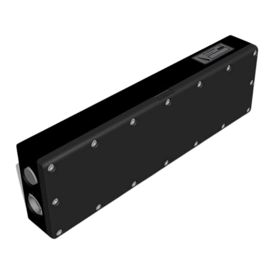
- Page 6 This tracking radar operates in the K-band and uses modulation to detect range and speed to the target in the radar beam. As part of a system, the RT2 is connected by one cable only. It provides both power and control from the system to the RT2. The control interface is designed on CANopen communication.
- Page 7 COMMAND SET 7/11...
- Page 8 Operational commands to control the RF section of the radar can be summarized into 2 functions: 1. Switch RF section ON / OFF 2. Set the frequency channel of the RF section Command ‘Switch RF section ON / OFF’ controls the RF transmitter output. When the system is operational, the RF is switched ON.
-
Page 9: Power Supply
POWER SUPPLY 9/11... - Page 10 All boards inside the RT2 have a dedicated voltage regulator for individual accurate supply voltages. Power supply specification for the RT2: RF OFF, 190 mA typ. @ 12 VDC RF ON, 230 mA typ. @ 12 VDC 10/11...
- Page 11 USER MANUAL RT2 VERSION: V1.0 11/11...
Need help?
Do you have a question about the RT2 and is the answer not in the manual?
Questions and answers