Table of Contents
Advertisement
Quick Links
Advertisement
Chapters
Table of Contents

Subscribe to Our Youtube Channel
Summary of Contents for ROBBE-Futaba FX-40
- Page 1 F X - 4 0 Version 1.1 Part 1, General Description, System and Base Menu 35 MHz No. F 8039 40 MHz No. F 8040 41 MHz No. F 8041...
-
Page 2: Table Of Contents
12.3 Model menu (helicopter) ..... .25 • FX-40 transmitter ......5 Basic information on using the system •... -
Page 3: Safety Notes
Please use only the com- ducts, or which are connected with such operation in any way. ponents and accessories which we expressly recommend, and always use genuine robbe-Futaba connectors. It is not permissible to make modifications of any kind to the system components. -
Page 4: General Description
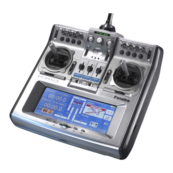
F X - 4 0 Introduction The FX-40 is a premium-class radio control system which sets The data can also be stored and backed-up on a PC which new standards in many areas. has a Compact Flash Card reader; it can also be sent by email. -
Page 5: Recommended Accessories
Specification Transmitter controls 3. SET CONTENTS 4. SPECIFICATION: 1 FX-40 FM transmitter with FX-FM RF amplifier FX-40 TRANSMITTER 1 LT4F 5000 Lithium transmitter battery, 7.4 Volts / 5000 mAh Control channels: . .8…12 FM / 10 PCM-1024 / 14 PCM-G3 1 12 Volt automatic Lithium battery charger, 7.4 V / 2 A... -
Page 6: General
Transmitter controls 5.1 GENERAL INFORMATION vel the ball mounting to the angle required, then tighten the The FX-40 transmitter is supplied with all transmitter controls locking screw again. The set is supplied with a 2.5 mm A/F installed as standard: allen key which fits the locking screw. -
Page 7: Linear Sliders
F X - 4 0 Transmitter controls In the Linkage menu “Dial Monitor” the current and stored positions of the rotary knobs are displayed in bar graph form. The centre rotary knob CD is a digital control with no end- stops, and it also features an integral push-button function (CD-SW). - Page 8 F X - 4 0 Transmitter controls the graphic LCD screen, with the result that the screen acts as an input method as well as just a display medium. It can be operated using a finger-tip or the stylus (supplied in the set). 2.
-
Page 9: Length Adjustment
F X - 4 0 Stick adjustment 5.2 STICK ADJUSTMENTS Stick ratchet / brake The stick units feature both a ratchet function (fixed-wing models) and a brake function (helicopters) for the throttle func- tion, which does not have a self-neutralising action. It is possi- ble to activate this function and adjust the ratchet / brake force. -
Page 10: Transferring Data To A Pc
F X - 4 0 Back panel sockets 5.4 DATA PACK CFDP32M DATA SECURITY The Data Pack (Compact The lifetime of a Data Pack card is more than 100,000 write Flash) card supplied can be cycles. If you experience read / write problems after a very used to store pictures, long period of frequent use, the card should be replaced. -
Page 11: Headphone Socket (Phone)
• The Pupil transmitter must be set to PPM (FM) modulation, (INA) Trainer mode in the “Trainer” set-up menu of the “System unless the Pupil unit is also an FX-40 or T14MZ transmitter. menu”. • If the transmitters are not set up with the same stick mode •... -
Page 12: Lithium Transmitter Battery
For this reason the battery is only suitable for use in the FX-40 transmitter. CURRENT DRAIN / OPERATING TIMES The LT4F5000 Lithium transmitter battery has a capacity of 5000 mAh. -
Page 13: Charging The Transmitter Battery
F X - 4 0 RF module Stick mode / Reset CHARGING THE TRANSMITTER BATTERY 5.10 INSTALLING AND REMOVING THE RF MODULE • Always switch off the transmitter before inserting the RF module. • Position the RF module squarely before pushing it into place. •... -
Page 14: Connecting The Servos And Receiver
F X - 4 0 Receiver sockets 6. CONNECTING SERVOS AND RECEIVER Connect the servos and the receiver as shown in the diagram. Socket: B/C = Receiver battery or DSC lead. Output 1 … 12 = 1 … 12 proportional channels for servos. As an option two of these outputs can be expanded to eight channels each by connecting Multi-Decoders. -
Page 15: Servo Assignment Tables
F X - 4 0 Servo socket sequence SERVO ASSIGNMENT TABLES FOR FIXED-WING MODEL AIRCRAFT WITH NORMAL TAIL (POWER MODELS, ELECTRIC GLIDERS, GLIDERS WITH T-TAIL, CROSS-TAIL OR V-TAIL) 1 Aileron - 1 Querruder 2 Aileron - 2 Querruder 2 Aileron+1 Flap - 2 Quer+1 Wölbklappe Airplane EP-Glider Glider... - Page 16 F X - 4 0 Servo socket sequence 4 Aileron+4 Flap - 4 Quer+2 Wölb+2 Bremsklappen NOTE! All model types are available Airplane EP-Glider Glider Kanal when twelve-channel PCM-G3 Motor E-Segler Segler mode is selected. If you select Elevator-Höhe Elevator-Höhe Elevator-Höhe FM 8-channel or PCM 1024, the Rudder-Seite...
- Page 17 F X - 4 0 Servo socket sequence 2 Aileron+2 Flap - 2 Quer+2 Wölbklappen 2 Aileron+4 Flap - 2 Quer+2 Wölb+2 Bremsklappen 4 Aileron+2 Flap - 4 Quer+ 2 Wölbklappen Airplane EP-Glider Glider Airplane EP-Glider Glider Airplane EP-Glider Glider Kanal Motor E-Segler...
-
Page 18: For Flying Wing Models
F X - 4 0 Servo socket sequence FOR FLYING WING MODELS (POWER MODELS, ELECTRIC GLIDERS AND GLIDERS WITH CENTRAL RUDDER OR WINGLET RUDDERS 2 Aileron - 2 Aileron-Quer 2 Aileron+1 Flap - 2 Quer+1 Wölbklappe 2 Aileron+2 Flap - 2 Quer+2 Wölbklappen Airplane EP-Glider Glider... - Page 19 F X - 4 0 NOTE! All model types are available when twelve-channel PCM-G3 mode is selected. If you select FM 8-channel or PCM 1024, the num- ber of available model types is reduced. In this case only the model types shown with a grey background are available. VC 1 …...
-
Page 20: Switching The Transmitter On / Off
F X - 4 0 Switching the transmitter on Changing the frequency channel 7. SWITCHING THE TRANSMITTER ON / OFF 8. CHANGING THE SPOT FREQUENCY • Locate the switch on the transmitter marked “Power”, and slide it to the right. The system incorporates a DD Synthesizer system which •... -
Page 21: Changing The Frequency Band
35 MHz band, and if this channel should already be in use by vel is more than 135%, the receiver may switch to hold-mode! another transmitter, it is possible that the FX-40 will not trans- It is absolutely essential that you check for system compatibi-... -
Page 22: Receiver Number
F X - 4 0 Changing the frequency band • Press the Modulation button • Select the modulation you wish to use, and press “Enter”. • The screen confirms your choice with the message “Modulation type is changed. sure ?” •... - Page 23 F X - 4 0 Start display 10. DESCRIPTION OF THE START DISPLAY The most important information relating to the transmitter pro- gramming is displayed on the Start screen. At the same time most of the display fields also constitute operating buttons, and you can move to the Set-up menu for the appropriate function simply by pressing the corresponding area of the Flight...
- Page 24 F X - 4 0 Menu structure Navigation 11. MENU STRUCTURE, METHOD OF NAVIGATING sub-level; in this case you can move to the next page or level by pressing the button field (1) at the top right-hand corner of The menu structure is divided up into three distinct Select the screen.
-
Page 25: System Menu
F X - 4 0 Select menus 12. SUMMARY OF SELECT MENUS 12.3 MODEL MENU (FIXED-WING AIRCRAFT) 12.1 SYSTEM MENU This menu contains the settings specific to each model type for each model memory, especially mixer functions. The Select menu varies This menu is used to adjust transmitter settings which apply to according to the model type you have selected: all models, i.e. -
Page 26: Transmitter Control Selection
This is the basis for the new operating The display for selecting transmitter controls for particular functions philosophy introduced in the FX-40 system. always looks the same; this again is to avoid possible confusion. The... - Page 27 F X - 4 0 Curve set-up • SETTING CONTROL CURVES / MIXER CURVES This section deals with the method of setting the characteristics of a The method of setting transmitter control travels and curves has also transmitter control, using the transmitter control travel (AFR) menu as been standardised in the interests of ease of operation.
- Page 28 F X - 4 0 Curve set-up EXP1 = 3-POINT CURVE (EXPONENTIAL) The “EXP1” function is used to alter the characteristic curve of the transmitter control into a non-linear (exponential) curve, symmetrical around the centre point. The exponential curve can be applied in either direction. •...
- Page 29 F X - 4 0 Curve set-up LINE = 17-POINT CURVE AND SPLINE = 17-POINT CURVE, ROUNDED The methods of setting and adjusting the Line and Spline curves are identical; the only difference with the Curve variant is that the transitions at the points on the Spline are mathematically rounded, producing a more harmonious shape.
-
Page 30: Player, For Playing Music Files
Media Audio Format (wma). The player does not support the mp3 file format; such files have to be converted to wma format before they can be played. If you visit the T14MZ / FX-40 sup- port page of the robbe website you will find information on... -
Page 31: System Menus
F X - 4 0 System menu 15. SYSTEM MENU This menu is used to adjust the basic transmitter settings, i.e. the settings which are not specific to individual model memo- ries. Settings entered here apply to all model memories. Trainer Trainer mode settings Display... -
Page 32: Trainer (Teacher / Pupil Function)
Rate. This determines the maximum extent of control which the Pupil has over the model. IMPORTANT: If the FX-40 transmitter is used as the Teacher unit, then it is absolutely essential to set the modulation on the Pupil trans- mitter to PPM. -
Page 33: Screen (Contrast, Backlight, Power-Off Time)
F X - 4 0 System menu 15.2 SCREEN (CONTRAST, BACKLIGHT, POWER-OFF TIME) In the “Display” Set-up menu you can adjust, select and cali- brate various aspects of the LCD screen. • Screen contrast setting • Screen backlight brightness setting •... -
Page 34: Date, Time, Calendar, System Time
F X - 4 0 System menu 15.3 DATE, TIME, CALENDAR, SYSTEM TIME 15.4 USER NAME, USER NUMBER, SECURITY MODE This Set-up menu allows you to set the time of day and the date. The menu also includes a calendar function covering the years 2000 …... -
Page 35: Switch Type Assignment
F X - 4 0 System Menü 15.5 SWITCH - SWITCH TYPE ASSIGNMENT 15.6 TRANSMITTER CONTROL SETTINGS / REVERSE STICK RESPONSE TIME ADJUSTMENT It is possible to alter the physical position of the switches A … H; the procedure is described on page 7 of these instructions. Set-up menu for hardware reversing of transmitter controls, for If you make changes to the physical location of the switches setting the response time of the sticks J1 …... -
Page 36: Information
F X - 4 0 Linkage Menu 15.7 INFORMATION 16. LINKAGE MENUS This menu provides information about the currently installed The table below shows a summary of the Linkage menu func- version of the operating system and the application software. tions, which are described individually in the next section. -
Page 37: Servo Monitor
F X - 4 0 Linkage Menu 16.1 SERVO MONITOR The Servo Monitor menu displays all servo travels in a clear form using a bar graph and percentage values. The travels are those which are generated by all the set adjustments and mixer functions. -
Page 38: Model Select / Model Memory Select
F X - 4 0 Linkage Menu New model memory 16.2 MODEL SELECT - MODEL MEMORY SELECT • Press the NEW button, and confirm the model change; at In this menu you can select the actual model memory file you this point the radio link is switched off wish to use, but it is also designed for model data handling •... -
Page 39: Model Type / Model Type Select
F X - 4 0 Linkage Menu 16.3 MODEL TYPE - MODEL TYPE SELECT MODEL TYPE HELI This is the menu where you select the model type, wing type and tail type for fixed-wing model aircraft, and the type of swashplate mixing for model helicopters. -
Page 40: Picture - Linking Pictures / Photos
F X - 4 0 Linkage Menu 16.4 PICTURE - LINKING PICTURES / PHOTOS IMPORTANT: In this menu point you can assign a picture of the model to the Pictures must be located on the D/P card. The transmitter only appropriate model memory;... -
Page 41: Sound (Music & Sound Files)
F X - 4 0 Linkage Menu 16.5 SOUND (MUSIC / SOUND FILES) IMPORTANT: In this menu point you can assign sound files to the various Sounds must be stored in the WAV folder on the D/P card. The switched functions. Each switch position can be allotted its transmitter only searches for sounds in that location, and if own sound, regardless of whether it is a physical switched they are stored anywhere else, they will not appear in the pre-... -
Page 42: Frequency (Selecting The Channel & Modulation)
35 MHz band, and if this channel is already in use by another does not work, switch the receiver off and on again. transmitter, the power of the FX-40 transmitter may not be suf- • When the receiver has picked up the signal and changed ficient for changing the spot frequency. -
Page 43: Function
F X - 4 0 Linkage Menu 16.7 FUNCTION NEW FUNCTION SEQUENCE The transmitter employs a new, graphical method of selecting the model type as basis for the mixer functions and transmitter For the PCM-G3 system the second aileron output has been control arrangement (stick mode), and this automatically gene- shifted to output 5, in order to maintain compatibility with rates the optimum configuration for the selected model type. - Page 44 ‘doubling up’ as elevators. Selecting the trims Each of the FX-40’s virtual functions features its own con- It is possible to select any trims you wish to use; simply press trol curve (AFR) with 2 … 17 points, providing an extre-...
-
Page 45: Servo Reverse
F X - 4 0 Linkage Menu 16.8 SERVO CENTRE 16.9 SERVO REVERSE SERVO CENTRE OFFSET This function is used to reverse the direction of servo rotation When you install the servos in a model, it is always best to electronically;... -
Page 46: Fail-Safe Settings
F X - 4 0 Linkage Menu 16.10 FAIL-SAFE The warning position for the selected servo is entered using FAIL-SAFE SETTINGS the method already described; the value is displayed on- This function is only available in PCM-G3 or PCM-1024 mode. screen in the form of a percentage. - Page 47 F X - 4 0 Linkage Menu 16.11 END-POINT (ATV) It is usually only necessarily to set the servo end-points SERVO TRAVEL SETTINGS (ATV) once for the maximum possible or desired travel, i.e. subse- quent corrections are not generally necessary. Individual This function provides a means of travel adjustments for particular flight modes can be adjusting servo travel separately for...
-
Page 48: Motor Cut-Off Function
F X - 4 0 Linkage Menu 16.12 MOTOR OFF - MOTOR CUT-OFF FUNCTION 16.13 IDLE 2 SELECTABLE 2nd THROTTLE SETTING This function enables you to cut the motor using a switch, without The ‘Idle 2’ function enables the pilot to use a physical switch changing the idle trim. -
Page 49: Swashplate Basic Swashplate Settings
• Linkage compensation Any unwanted interactions between the various pushrods can be corrected in the right frame on the second screen The software of the FX-40 provides a very convenient method page. of optimising the swashplate settings. • Speed compensation •... - Page 50 The Stopwatch menu is used to set up and adjust the electro- nic timers provided by the FX-40 transmitter. The timers are When you define a switch for recording individual times (lap displayed in two on-screen windows, which means that you times), an additional ‘List’...
- Page 51 F X - 4 0 Linkage Menu 16.16 TRIM / ADJUSTOR POSITION DISPLAY 16.17 RESETTING DATA The ‘Trim display’ function shows the current and stored posi- When you wish to enter the essential data for a new model, tions of the digital trims in graphic form, as also the positions you will often need to start by erasing the contents of a model of the linear sliders L1, L2 and L3 and the auxiliary transmitter memory which you no longer need, or just certain areas of that...
-
Page 52: Flight Mode Hold
F X - 4 0 Linkage Menu 16.18 FLIGHT MODE HOLD The purpose of this function is to enable you to change the settings in a different flight mode. The motor is held at the ‘idle’ setting, to prevent it being switched on accidentally. CND HOLD can only be activated when the “Normal”... - Page 53 F X - 4 0 Part 2, model menus for fixed-wing model aircraft and helicopters, additional information, guarantee, Service Centre addresses, regulations Version 1.1 35 MHz No. F 8039 40 MHz No. F 8040 41 MHz No. F 8041...
- Page 54 Mixture adjustment .....63 A General Description of the FX-40 and an explanation of the Model menus (fixed-wing model aircraft) . . .64 System menu and Base menu are included in Part 1 of these 18.1...
-
Page 55: Model Menus
F X - 4 0 Model menu 17. MODEL MENUS • MODEL MENU - OVERVIEW OF MODEL HELICOPTERS This menu is used for programming the model type-specific settings for individual model memories - especially the mixer functions. This data is stored under the programmed model name in the appropriate memory. -
Page 56: Selecting Flight Modes
17.1 SELECTING FLIGHT MODES Mark the field for selecting the flight mode switch (currently NONE). The software of the FX-40 provides up to eight flight modes for each individual model memory. This feature ensures that you can always store the optimum settings for the various phases of a typical flight, and call them up as and when required sim- ply by operating a switch. - Page 57 F X - 4 0 Model menu Flight modes delay time as standard. Now move to the ‘Delay’ column and mark the field for the channel which is to be assigned a delay time. You will now see an additional set of three button fields in the bottom right corner of the screen.
-
Page 58: Transmitter Control Travel / Dual Rate Curve
F X - 4 0 Model menu Transmitter control travel / Dual Rates 17.2 TRANSMITTER CONTROL TRAVEL / DUAL RATE Please note: the higher the number, the more slowly the CURVE servo moves. The maximum value (27 increments) corres- ponds to a duration of nine seconds. The default setting is The purpose of the AFR function is to adjust the basic settings always ‘0’. - Page 59 F X - 4 0 Model menu Transmitter control travel / Dual Rates As an additional feature, the fields ‘Rate A and B’ can be mar- ked to adjust the transmitter control travel separately for each side of centre. If you select a VTR curve, addi- tional set-up...
-
Page 60: Programmable Mixers
You move to the actual programming masks by marking the appropriate field in the ‘Mixer’ column on the left. The display The FX-40 features ten freely programmable mixers which are changes, and the first mixer programming menu appears. available for every model memory, in addition to the fixed pre- programmed mixer functions. - Page 61 F X - 4 0 Model menu Programmable mixers It is also possible to select a mode for the programmable The link mode can be set from ‘Off’ mixer, i.e. linear (LIN) or symmetrical (SYM) mode; you can (default; no display in the field) to ‘+’ or toggle between the two simply by touching the appropriate ‘-’.
- Page 62 F X - 4 0 Model menu Programmable mixers appropriate field, and select your preferred transmitter con- Linear: linear curve trol in the menu which then appears. Any of the auxiliary EXP1: exponential curve (curve 1) transmitter controls can be used. Your selected control is EXP2: exponential curve (curve 2) displayed in the field, as shown in the screen shot.
- Page 63 When you mark one of the fields ‘there’ or ‘back’, the but- ton fields for the arrows appear at the right margin. It is pos- The comprehensive nature of the FX-40’s programmable sible to make adjustments in steps of one increment or ten mixers makes them suitable for a very wide range of special increments.
-
Page 64: Mixture Adjustment
F X - 4 0 Model menu Mixture adjustment 17.4 MIXTURE ADJUSTMENT (power model and helicopter model types only) This function is designed for fine-tuning the fuel mixture at the carburettor using a separate servo. A special advantage of this system is the ability to set up an inter-action with the normal throttle function. -
Page 65: Model Menus (Fixed-Wing Model Aircraft)
This screen shot shows a typical example of programming for this sub-menu. • Settings for particular throttle states The software of the FX-40 provides two fixed throttle states which you can adjust and call up at any time; these have already been described in the Base menu. -
Page 66: Aileron Differential
Rate settings. Dual Rate values can be set at this point, in servo must be parallel with the programming facilities which are described used for each in Section 17.2 on page 57. control surface. The FX-40 soft- ware allows Aileron 1 Aileron 2 you to assign... -
Page 67: Wing Flap Settings
F X - 4 0 Model menu Wing flap settings This screen shot shows aileron differential programmed to 18.2 WING FLAP SETTINGS 50%. This menu is used for ente- ring the set- tings for all the inboard wing flaps. If your Brake Brake model features... -
Page 68: Aileron ? Flap Mixer
F X - 4 0 Model menu Aileron -> flap mixer 18.3 AILERON -> FLAP MIXER 18.4 AILERON -> BRAKE FLAP MIXER This menu is This menu is used to set the used for setting values mixer mixer which which causes causes the brake flaps spoiler... -
Page 69: Aileron ? Rudder Mixer
F X - 4 0 Model menu Aileron -> rudder mixer 18.5 AILERON -> RUDDER MIXER • Selecting the fine-tuning settings It is possible to assign a switch or other transmitter control This menu is to the task of fine-tuning aileron differential; this is carried Winglet Winglet used for setting... -
Page 70: Airbrake ? Elevator Mixer
(Fine). The mode is selected in the usual way. applying down-elevator manually. The FX-40 includes a mixer which carries out this correction automatically. Once you have selected a transmitter control for fine-... -
Page 71: Rudder ? Aileron Mixer
F X - 4 0 Model menu Rudder -> aileron mixer 18.7 RUDDER -> AILERON MIXER • Selecting the fine-tuning settings It is possible to assign a switch or other transmitter control This menu is to the task of fine-tuning this mixer. You can select this Winglet Winglet used for setting... -
Page 72: Spoiler (Flap) Mixer
F X - 4 0 Model menu Spoilers 18.8 SPOILER (FLAP) MIXER In the second frame the AFR settings are entered for the cam- ber-changing flap mixer. This sub-menu is accessed by mar- This menu is king the ‘Spoiler AFR’ field; the screen display now looks like aileron used for setting this:... -
Page 73: Elevator ? Flap Mixer
F X - 4 0 Model menu Elevator -> flap mixer 18.9 ELEVATOR -> SPOILER (FLAP) MIXER Once you have selected a transmitter control for fine- tuning, and programmed your preferred mode, you should This menu is used for setting up a mixer which causes all the determine the effect range for the fine-tuning procedure. -
Page 74: Flap ? Elevator Mixer
F X - 4 0 Model menu Flap -> elevator mixer 18.10 FLAP -> ELEVATOR MIXER • Selecting the fine-tuning settings It is possible to program a switch or transmitter control This menu is which is used to carry out fine adjustments (fine-tuning) of used for setting the mixer settings. -
Page 75: Butterfly (Crow) Mixer
F X - 4 0 Model menu Butterfly (Crow) mixer 18.11 BUTTERFLY (CROW) MIXER If you wish to program a delay time to provide a smooth tran- sition when you switch flight modes, you must first mark the This menu is ‘Delay’... -
Page 76: Trim Mix 1 And 2
(AIL) (AIL2) phases. Brake flaps software of the (BRFL & BRFL2) FX-40 provides two flight phase mixers (Trim Mix ELE2 ELE2 1 and 2), but V-tail Ailvator both mixers are programmed in exactly the same way, so this Section only describes the set- up procedure for the first mixer. - Page 77 F X - 4 0 Model menu Trim Mix 1 and 2 The Trim Mix function first has to be activated in the Status An Offset value can be entered separately for each control sur- line. Mark the field, and the same field then displays ‘ON’ or face, by marking the appropriate field and then entering the ‘OFF’...
-
Page 78: Gyro Settings
F X - 4 0 Model menu Gyro settings 18.13 GYRO SETTINGS This screen shot shows a sensible programming set-up for the Gyro function. If you wish to use a gyro in a fixed-wing model aircraft in order to stabilise one flight axis, this is the menu you use for entering You should program a gain value for each gyro installed in your the settings for the gyro. -
Page 79: V-Tail Settings
F X - 4 0 Model menu V-tail / Ailvator 18.14 V-TAIL SETTINGS 18.15 AILVATOR ELEVATOR WITH AILERON FUNCTION This menu presents all the mixer functions required for controlling This menu presents all the mixer a V-tail, which involves superim- functions required for controlling a posing the signals from the rud- pair of elevators which are also... -
Page 80: Winglet Rudder Settings
F X - 4 0 Model menu Ailvator / Winglet 18.16 WINGLET RUDDER SETTINGS This menu pre- sents mixer functions required for con- Rudder trolling rudder panels in the win- glets of a fixed- Rudder2 wing model air- This programming set-up allows two elevator servos to be craft. -
Page 81: Motor Settings
F X - 4 0 Model menu Motor 18.17 MOTOR SETTINGS ‘Speed 1’ and ‘Speed 2’. This facility includes the option of setting different delay times for each direction of switching This menu is used for entering the settings for switching an (‘there’... -
Page 82: Rudder ? Elevator Mixer
F X - 4 0 Model menu Rudder -> elevator Snap roll 18.18 RUDDER -> ELEVATOR MIXER 18.19 SNAP ROLL FUNCTION (flying wing models only) The snap roll function enables you to define transmitter control Many flying wings exhibit a tendency to dive slightly when a positions which cause the aeroplane to carry out a particular rudder command is given, and the purpose of this mixer is to flight manoeuvre. -
Page 83: Multi-Motor Settings For Multi-Motor Models
F X - 4 0 Model menu Snap roll Multi-motor 18.20 MULTI-MOTOR SETTINGS FOR MULTI-MOTOR MODELS This function enables you to define the most important set- tings for controlling the motors in a model aircraft with up to four power plants. These settings are as follows: •... -
Page 84: Model Menus (Model Helicopters)
F X - 4 0 Model menu Model helicopters 19. MODEL MENUS (MODEL HELICOPTERS) This Section analyses the settings which are specific to model helicopters, i.e. it only covers those options which have not already been described in Section 17 (see page 54). Activate the Model menu by touching the field showing the picture of the model aircraft in the main picture screen. -
Page 85: Collective Pitch Curve Settings
Idle-up 3: for aerobatics be allocated a maximum of seventeen variable points. The FX-40 Auto-rotation: for auto-rotation landings also offers switchable flight modes which enable the pilot to set... - Page 86 F X - 4 0 Model menu Collective pitch curve A typical curve for It is also possible to adjust the trim rate (Rate), or trim travel. the ‘Auto-rotation’ The adjustment range is infinitely variable between 0 and flight mode; the 30% of transmitter control travel;...
-
Page 87: Throttle Curve Settings
The FX-40 also offers swit- chable flight modes which enable the pilot to set up the opti- mum throttle curve for each individual flight mode. - Page 88 F X - 4 0 Model menu Throttle curve motor speed • Trimming the throttle setting remains as nearly The throttle trim can be optimised using the ‘Trim’ switch constant as possi- field, which is located at the left of the bottom line. Mark the ble over the full field, and the display changes to look like this, e.g.
-
Page 89: Acceleration Function
F X - 4 0 Model menu Throttle curve / Acceleration The ‘Display’ switch field is used to define which of the pro- 19.3 ACCELERATION FUNCTION grammed throttle curves is to be shown in the graphic display, or which combination of curves. The options are as follows: The purpose of this function is to prevent abrupt changes affecting the throttle and collective pitch functions when you Separate:... -
Page 90: Auto-Rotation Settings
F X - 4 0 Model menu Auto-rotation 19.4 AUTO-ROTATION SETTINGS The next step is to set the carburettor position for auto-rota- tion, in the form of a percentage figure in the ‘Off Pos.’ or ‘Idle This option is used for entering the settings for auto-rotation, Offs.’... -
Page 91: Swashplate Mixer
F X - 4 0 Model menu Swashplate mixer 19.5 SWASHPLATE MIXER SET-UP EXAMPLE: SWASHPLATE MIXER (virtual swashplate rotation) Programming the swashplate mixer can be a complex proce- dure, so the next section describes a complete example in This function is used to set up the swashplate accurately over order to clarify the process. - Page 92 F X - 4 0 Model menu Swashplate mixer tive pitch stick to max. collective, and set a value for the ‘Roll The correct settings can then be set while you are still in the mixer’ to eliminate any change in the pitch-axis travel at full ‘Swashplate AFR’...
-
Page 93: Throttle / Motor Mixer
F X - 4 0 Model menu Throttle mixer 19.6 THROTTLE MIXER vels of the transmitter stick (left and right): mark the field and SWASHPLATE -> THROTTLE MIXER enter the values required using the arrow buttons. The setting is displayed in the field as a percentage value. You can also This function is used to program a mixer which affects the enter a percentage value in the ‘Damping’... - Page 94 F X - 4 0 Model menu Collective pitch -> needle valve Collective pitch -> tail rotor 19.7 COLLECTIVE PITCH -> NEEDLE VALVE MIXER 19.8 COLLECTIVE PITCH -> TAIL ROTOR MIXER (REVOLUTION MIXER) This function is used to program an automatic needle valve adjustment which follows the movement of the collective pitch The purpose of this function is to detect torque fluctuations at stick.
- Page 95 F X - 4 0 Model menu Collective pitch -> tail rotor Mixture adjustment ting - regardless of the speed with which you change the set- 19.9 MIXTURE ADJUSTMENT ting. The same applies at the opposite extreme: when you reduce motor torque or the collective pitch setting, the heli- This function is used to set up a separate servo for adjusting copter must not rotate around its vertical axis.
-
Page 96: Gyro Settings
F X - 4 0 Model menu Gyro settings 19.10 GYRO SETTINGS If you need to reverse the direction of effect, mark the field containing the prefix, and it will change from ‘+’ to ‘-’; the fine- This function is used for adjusting gyro gain (sensitivity) from tuning now works in the opposite direction to the previous set- the transmitter. -
Page 97: Speed Governor (Regulator) Settings
F X - 4 0 Model menu Speed governor settings 19.11 SPEED GOVERNOR SETTINGS the transmitter to those of the GV-1 speed governor. Activate the speed pre-set (Rate 1, 2 or 3) for which you wish to carry This function enables you to adjust the settings of a speed out the calibration, then select the rotational speed display governor (regulator) from the transmitter. -
Page 98: Flight Mode Hold
F X - 4 0 Model menu Flight mode hold Notes on the stopwatch 19.12 FLIGHT MODE HOLD 19.13 NOTES REGARDING THE STOPWATCH WHEN USED WITH THE ‘HELICOPTER’ MODEL TYPE The purpose of this function is to enable you to carry out adjustments in another flight mode. -
Page 99: Tips On Installing The Receiving System
F X - 4 0 Tips and notes TIPS ON INSTALLING THE RECEIVING SYSTEM ground tend to cancel each other out or amplify each other 20.1 INSTALLING AND USING RECEIVERS (timing differences of the two waves). Indoor flying - in sports halls, for example - often takes place in buildings of steel or In the last few years the technical equipment carried in our steel-reinforced concrete construction, where multiple reflec-... -
Page 100: Installing The Receiver
F X - 4 0 Tips and notes The following solution has proved highly effective in practice: • Turbines: Mount the aerial on a hardwood former inside the fuselage, • Connect the turbine shield plate using an earth strap to and run it through a hole of around 10 mm Ø... -
Page 101: Range Checking
• To avoid ‘hold-mode moments’, the effective range of the FX-40 under these conditions should be around 60 metres A range of servo output arms is available for robbe servos, and with the transmitter aerial removed. - Page 102 Be sure to select a receiver battery with ample capacity, bearing in mind the likely current drain and the number of All robbe-Futaba receivers continue to work with full range at servos in the model. reduced voltage, down to the point where the supply voltage falls to 3 V.
- Page 103 F X - 4 0 22. GUARANTEE 24. POST OFFICE REGULATIONS We guarantee this radio control system for a period of 24 The R&TTE (Radio Equipment & Telecommunications Terminal months. Please keep the purchase receipt given to you by Equipment) directive is the new European regulation which your model shop, as you will need it as proof of the guarantee applies to radio systems and telecommunications equipment, period.
- Page 104 Trainer lead No. F 1591 No. 8448 to a flight simulator Skysport T4YF, T4EX, FF9, No. 8239 T12Z, T14MZ, FX-40 Skysport T4YF, T4EX, FF9, T12Z, T14MZ, FX-40 Y-lead No. F 1423 Switch harness with charge For connecting two servos in socket No.
- Page 105 This symbol means that you must dispose of electrical and electro- nic equipment separately from the general household waste when it reaches the end of its useful life. Take your unwanted equipment to your local specialist waste collection point or recycling centre. This applies to all countries of the European Union, and to other Euro- pean countries with a separate waste collection system.
Need help?
Do you have a question about the FX-40 and is the answer not in the manual?
Questions and answers