Table of Contents
Advertisement
Advertisement
Table of Contents

Summary of Contents for Honda Power Products EG5000CX
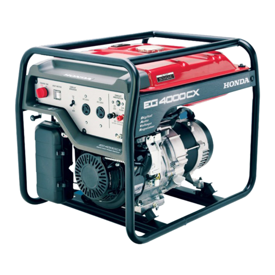
- Page 1 GENERATOR EG4000CX EG5000CX • EG6500CX EG6500CXS • OWNER'S MANUAL...
- Page 2 EG4000CX · EG5000CX Honda EU20i EG6500CX · EG6500CXS OWNER’S MANUAL Original instructions...
-
Page 4: Table Of Contents
CONTENTS GENERATOR SAFETY ................2 SAFETY ....................... PRE-OPERATION CHECK IMPORTANT SAFETY INFORMATION ..........2 ................ENGINE OIL LEVEL Operator Responsibility ..............2 ................. FUEL LEVEL Carbon Monoxide Hazards ............... 2 ..................... AIR CLEANER ..................Electric Shock Hazards ..............3 BATTERY SERVICE (electric starter type only) Fire and Burn Hazards ............... -
Page 5: Generator Safety
GENERATOR SAFETY IMPORTANT SAFETY INFORMATION Honda generators are designed for use with electrical equipment that has suitable power requirements. Other uses can result in injury to the operator or damage to the generator and other property. Most injuries or property damage can be prevented if you follow all instructions in this manual and on the generator. -
Page 6: Electric Shock Hazards
GENERATOR SAFETY Electric Shock Hazards • The generator produces enough electric power to cause a serious shock or electrocution if misused. • Do not use in wet conditions. Keep the generator dry. – Do not use in the rain or snow. –... -
Page 7: Pre-Operation Check
PRE-OPERATION CHECK ENGINE OIL LEVEL Before each use, look around and underneath the engine for signs of oil or gasoline leaks. Check the engine oil level with the generator on a level surface and the engine stopped. ENGINE OIL LEVEL Recommended oil: Check the engine oil level with the generator on a level surface and the 4-STROKE MOTOR OIL SAE 10W-30... -
Page 8: Fuel Level
PRE-OPERATION CHECK FUEL LEVEL Never use an oil/gasoline mixture or dirty gasoline. Fuel tank capacity: 24.0 L Check the fuel level. If the fuel level is low, fill the fuel to the upper level. FUEL TANK CAP UPPER LEVEL MARK (RED) FUEL GAUGE FUEL TANK CAP UPPER LEVEL... -
Page 9: Air Cleaner
PRE-OPERATION CHECK AIR CLEANER Remove the air cleaner cover taking care not to damage it. Unsnap the air cleaner cover clips and pull the air cleaner cover. Free the hooks from the setting pins. Remove to the right side of the frame pipe. HOOK SETTING PIN CLIP... - Page 10 PRE-OPERATION CHECK Reinstall the air cleaner cover. Place the air cleaner cover over the air cleaner case. Set the hooks to the setting pins securely. Push the air cleaner cover to lock the clips. HOOK AIR CLEANER CASE SETTING PIN CLIP AIR CLEANER COVER Be sure that the air cleaner cover is set securely.
-
Page 11: Battery Service (Electric Starter Type Only)
PRE-OPERATION CHECK BATTERY SERVICE (electric starter type only) Your generator’s engine charging system charges the battery while the engine is running. However, if the generator is only used periodically, the battery must be charged monthly to maintain the battery service life. The battery contains sulfuric acid (battery fluid), which is highly corrosive and poisonous. - Page 12 PRE-OPERATION CHECK The battery fluid level must be kept between the UPPER and LOWER level marks. If the battery fluid level is below the LOWER level, sulfation and battery plate damage will occur. If rapid loss of battery fl uid is experienced, or if your battery seems to If rapid loss of battery fluid is experienced, or if your battery seems to be weak causing slow operation of the starter motor, see your be weak causing slow operation of the starter motor, see your...
-
Page 13: Starting The Engine
STARTING THE ENGINE Make sure that the AC circuit breaker is in the OFF position. SH, MH, RH, KH types LDH type S1H, MH, RH, REH, KH types LD1H type AC CIRCUIT BREAKER Turn the fuel valve lever to the FUEL VALVE LEVER ON position. - Page 14 STARTING THE ENGINE Start the engine. Using the electric starter: Turn the engine switch to the START START position, and hold it there until the engine starts. When the engine starts, release the key, allowing the switch to return to the ON position.
-
Page 15: Oil Alert System
STARTING THE ENGINE If the choke knob was moved to the CLOSED position, move to the OPEN position as the engine warms up. OPEN CHOKE KNOB Oil Alert System The Oil Alert system is designed to prevent engine damage caused by an insufficient amount of oil in the crankcase. - Page 16 Rated capacity: EG4000CX 3.2 kVA (MH, RH, KH types) (MH, RH, REH, KH types) 3.6 kVA (LDH type) (LD1H type) EG5000CX 4.0 kVA (MH, RH, KH types) (MH, RH, REH, KH types) 4.5 kVA (SH, LDH types) (S1H, LD1H types) EG6500CX·EG6500CXS 5.0 kVA...
-
Page 17: Generator Use
GENERATOR USE Turn the AC circuit breaker to the ON position. Confirm that the appliance to be used is switched off, and plug in the appliance. SH, RH, KH types S1H, RH, REH, KH types MH type AC CIRCUIT BREAKER AC CIRCUIT BREAKER PLUG PLUG... - Page 18 GENERATOR USE Turn on the equipment to be used. An overloaded AC circuit will switch off the AC circuit breaker. If this happens, reduce the load on the circuit, and wait a few minutes before switching on. SH, MH, RH, KH types S1H, MH, RH, REH, KH types LDH type LD1H type...
- Page 19 Total Current Available: S1H type: SH type: 20.5 A 20.5 A (EG5000CX) (EG5000CX) 25.0 A 25.0 A (EG6500CX·EG6500CXS) (EG6500CX·EG6500CXS) RH, KH types: 14.5 A...
- Page 20 RECEPTACLE No.5 shown below and the total load does not exceed the total current available. Total Current Available: 30.0 A (EG4000CX) 37.5 A (EG5000CX) 45.8 A (EG6500CX·EG6500CXS) Receptacles Available power Available power Receptacles EG4000CX EG5000CX EG6500CX·EG6500CXS...
- Page 21 GENERATOR USE DC Application The DC terminals may be used for charging 12 volt automotive-type batteries only. Connect the charging cable to the DC terminals and battery terminals in numerical order as shown. to positive ( ) battery terminal + +...
- Page 22 STOPPING THE ENGINE In emergency, turn the engine switch to the OFF position. In normal use: Switch off the connected appliance and pull off the plug. Turn the AC circuit breaker to the OFF position. SH, MH, RH, KH types LDH type S1H, MH, RH, REH, KH types LD1H type...
-
Page 23: Maintenance Schedule
MAINTENANCE Maintenance Schedule REGULAR SERVICE PERIOD First Every Every Every Perform at every indicated month Each 3 months 6 months years Page month or operating hour interval, whichever comes first. 20 hrs. 50 hrs. 100 hrs. 300 hrs. ITEM Engine oil Check level Change Air cleaner... - Page 24 MAINTENANCE ENGINE OIL CHANGE Remove the oil filler cap/dipstick and oil drain plug to drain the oil. SEALING WASHER (Replace) OIL DRAIN PLUG OIL FILLER CAP/DIPSTICK Install the oil drain plug, and tighten it securely. Fill to the upper level with the recommended oil (see page ). Engine oil capacity: 1.1 L UPPER LEVEL...
- Page 25 MAINTENANCE AIR CLEANER SERVICE Remove the air cleaner cover taking care not to damage it. Unsnap the air cleaner cover clips and pull the air cleaner cover. Free the hooks from the setting pins. Remove to the right side of the frame pipe. Remove the air cleaner element from the air cleaner case and clean it.
- Page 26 MAINTENANCE Install the air cleaner element to the air cleaner case. Reinstall the air cleaner cover. Place the air cleaner cover over the air cleaner case. Set the hooks to the setting pins securely. Push the air cleaner cover to lock the clips. HOOK AIR CLEANER CASE SETTING PIN...
- Page 27 MAINTENANCE SPARK PLUG SERVICE Recommended spark plug: BPR5ES (NGK) Never use a spark plug with an improper heat range. SPARK PLUG WRENCH Remove the spark plug cap and then remove the spark plug using a spark plug wrench. Clean the spark plug with a wire brush.
-
Page 28: Sediment Cup Cleaning
MAINTENANCE SEDIMENT CUP CLEANING Gasoline is extremely flammable and is explosive under certain conditions. Do not smoke or allow flames or sparks in the area. Type with electric starter: Turn the engine switch to the OFF position and remove the key. Type without electric starter: Turn the engine switch to the OFF position. -
Page 29: Fuse (Electric Starter Type Only)
MAINTENANCE FUSE (electric starter type only) If the fuse is blown, the starter motor will not operate. If the fuse is blown, the starter motor won’t operate. In the event of fuse failure, locate the cause of failure and repair it In the event of fuse failure, locate the cause of failure and repair it before you continue operation. - Page 30 STORAGE Gasoline is extremely flammable and is explosive under certain conditions. Do not smoke or allow flames or sparks in the area. DRAIN SCREW Drain the fuel from the fuel tank. Loosen the drain screw and drain the carburetor. Change the engine oil (see page Slowly pull the starter grip until resistance is felt.
- Page 31 TROUBLESHOOTING When the engine will not start: Is there fuel in Refill the fuel the tank? tank. Is the fuel valve Turn the fuel lever ON? valve lever ON. Is the engine Turn the engine switch ON? switch ON. Is the enough oil Is there enough Add the in the engine?
- Page 32 TROUBLESHOOTING No electricity at the AC receptacles: Is the AC circuit Turn the AC circuit breaker ON? breaker ON. Check the Replace the electrical electrical appliance DEFECT appliance or or equipment. equipment for Take the electrical any defects. appliance or equipment to an electrical shop for NO DEFECT...
- Page 33 TROUBLESHOOTING When the engine is stopped: Is there fuel in Refill the fuel the tank? tank. Is the enough oil Is there enough Add the in the engine? recommended oil. oil in the engine? Turn engine switch to OFF and restart the engine.
- Page 34 Maximum output 12 V Rated voltage 12 V Rated voltage output output 8.3 A Rated current 8.3 A Rated current Model EG5000CX Model EG5000CX Type Type LD1H Rated voltage 220 V 220 V 120 V/240 V 120 V/240 V 220 V...
-
Page 35: Battery Tray Kit
INSTALLATION OF KIT PARTS STANDARD KIT PARTS EG6500CXS Electric starter type: Battery Tray Kit Install the battery guard pipe on the frame. Set the battery tray on the battery guard pipe and tighten the bolts. Route the starter cable under the tank and connect it to the starter solenoid. - Page 36 INSTALLATION OF KIT PARTS STARTER CABLE (Positive) BATTERY GROUND CABLE CABLE TIE STARTER SOLENOID (16) (17) (14) (13) (11) (12) (15) (10) BATTERY SET BOLT BATTERY TRAY BATTERY SET PLATE (10) BATTERY GUARD PLATE 6 mm FLANGE NUT (11) BATTERY BOX BATTERY GROUND CABLE (12) 6 30 mm FLANGE BOLT...
-
Page 37: Four Wheel Kit Installation
INSTALLATION OF KIT PARTS OPTIONAL KIT PARTS Four Wheel Kit Installation Install the lock plate and four wheels on the wheel shaft using the plain washers and split pins. Install the front wheel shaft on the front side nearest the engine. ×... - Page 38 Honda Motor Co., Ltd. 2014 4MZ30602 英 西 アラ 00X4M-Z30-6020 Printed in China...
Need help?
Do you have a question about the EG5000CX and is the answer not in the manual?
Questions and answers