Table of Contents
Advertisement
Quick Links
Advertisement
Table of Contents

Summary of Contents for Morbark 20
- Page 1 Operator’s Manual Morbark Integrated Control System Model 20 Chipper...
-
Page 3: Table Of Contents
Contents Introduction Parts Identification Display Module Display Pages Main Page Engine Information Page Feed Control Page Control Devices Page Performance Adjustment Pages AutoFeed Settings Page Control Select Page Menu System Accessing the Menu Sub-Menus Adjust Menu Measure Preferences Info Troubleshooting... -
Page 4: Introduction
Also, every page has a section describing what each button on the Display Module does and the corresponding page number for that specific function. Operator’s Manual, Morbark Integrated Control System—Model 20 Chipper... - Page 5 Point-of-operation guarding devices must be installed and maintained to meet OSHA and ANSI Machine safety stan- dards. The manufacturer shall not accept responsibility for installation, application, or safety of systems Operator’s Manual, Morbark Integrated Control System—Model 20 Chipper...
-
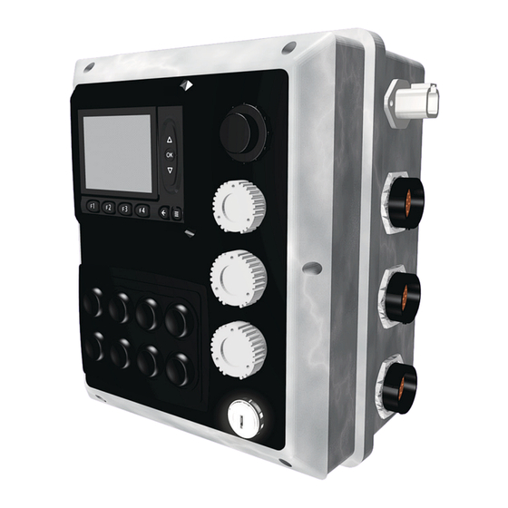
Page 6: Parts Identification
This section describes all connectors and switches located on the exterior of the control panel, valve driver and the Display Module. Control Panel Front View Control Panel Left View Control Panel Right View Operator’s Manual, Morbark Integrated Control System—Model 20 Chipper... - Page 7 Right Track Reverse • Left Track Forward • Left Track Reverse • Spout Left • Spout Right • Winch In • Winch Out • Track Drive High • Track Drive Enable • Fan Reverse Operator’s Manual, Morbark Integrated Control System—Model 20 Chipper...
- Page 8 “Function” buttons — These buttons can be used from within any page in the system. Their functionality is dependant on the page that is currently displayed. A more in-depth descrip- tion will be given on a per-page basis. Display Screen Operator’s Manual, Morbark Integrated Control System—Model 20 Chipper...
-
Page 9: Display Module Display Pages
Display Module Display Pages Display Module Display Pages Main Page Engine Information Page Feed Control Page Control Devices Page Operator’s Manual, Morbark Integrated Control System—Model 20 Chipper... - Page 10 When the green light is on next to Channel of the Machine’s Control Devices (Panel, Radio Transmitter and Tether) the desired control device press the “OK” button Press the “F4” button to return to the previous page Operator’s Manual, Morbark Integrated Control System—Model 20 Chipper...
-
Page 11: Main Page
F4 Button — Press to navigate to the “Control Select” Page* F3 Button — Not used on the current screen F2 Button — Not used on the current screen F1 Button — Not used on the current screen Operator’s Manual, Morbark Integrated Control System—Model 20 Chipper... -
Page 12: Engine Information Page
F4 Button — Press to navigate to the “Control Select” Page F3 Button — Not used on the current screen F2 Button — Not used on the current screen F1 Button — Not used on the current screen Operator’s Manual, Morbark Integrated Control System—Model 20 Chipper... -
Page 13: Feed Control Page
F4 Button — Press to navigate to the “Control Select” Page F3 Button — Not used on the current screen F2 Button — Press to navigate to the “Autofeed Setup“ option F1 Button — Not used on the current screen Operator’s Manual, Morbark Integrated Control System—Model 20 Chipper... -
Page 14: Control Devices Page
F4 Button — Press to navigate to the “Control Select” Page F3 Button — Not used on the current screen F2 Button — Not used on the current screen F1 Button — Not used on the current screen Operator’s Manual, Morbark Integrated Control System—Model 20 Chipper... -
Page 15: Performance Adjustment Pages
Performance Adjustment Pages Performance Adjustment Pages AutoFeed Settings Page Control Select Page Operator’s Manual, Morbark Integrated Control System—Model 20 Chipper... - Page 16 “OK” button two(2) times, this will open the desired adjustment option. Note: All modifications discussed in this section can be reset to “Factory Defaults” by pressing the “F2” button from within the option’s adjustment page. Operator’s Manual, Morbark Integrated Control System—Model 20 Chipper...
-
Page 17: Autofeed Settings Page
F4 Button — Not used on the current screen F3 Button — Not used on the current screen F2 Button — Press to reset all values to “Factory Default” F1 Button — Press to return to the “Main” menu screen Operator’s Manual, Morbark Integrated Control System—Model 20 Chipper... -
Page 18: Control Select Page
F4 Button — Not used on the current screen F3 Button — Not used on the current screen F2 Button — Press to reset all values to “Factory Default” F1 Button — Press to return to the “Main” menu screen Operator’s Manual, Morbark Integrated Control System—Model 20 Chipper... -
Page 19: Menu System
Performance Adjustment Pages Menu System Accessing the Menu Operator’s Manual, Morbark Integrated Control System—Model 20 Chipper... - Page 20 Machine. Contained within this section: • Accessing the Menu System — Access the Menu System to make performance adjustments to the Machine or adjust settings specific to the Display Module Operator’s Manual, Morbark Integrated Control System—Model 20 Chipper...
-
Page 21: Accessing The Menu
F4 Button — Press to navigate to the “Info” sub-menu F3 Button — Press to navigate to the “Preferences” sub-menu F2 Button — Press to navigate to the “Measure” sub-menu F1 Button — Press to navigate to the “Adjust” sub-menu Operator’s Manual, Morbark Integrated Control System—Model 20 Chipper... -
Page 23: Sub-Menus
Performance Adjustment Pages Sub-Menus Adjust Menu Measure Preferences Info Operator’s Manual, Morbark Integrated Control System—Model 20 Chipper... - Page 24 OEM only. • Preferences Menu — Allows modification of settings specific to the Display Module • Info Menu — Provides quick access to information about the Machine Operator’s Manual, Morbark Integrated Control System—Model 20 Chipper...
-
Page 25: Adjust Menu
F4 Button — Not used on the current screen F3 Button — Not used on the current screen F2 Button — Not used on the current screen F1 Button — Press to return to the “Main” menu page Operator’s Manual, Morbark Integrated Control System—Model 20 Chipper... -
Page 26: Measure
F4 Button — Not used on the current screen F3 Button — Not used on the current screen F2 Button — Not used on the current screen F1 Button — Press to navigate to the “Main” menu page Operator’s Manual, Morbark Integrated Control System—Model 20 Chipper... -
Page 27: Preferences
F3 Button — Press to set the “Language” for the Display Module system F2 Button — Press to set the “Date/Time” for the Display Module system F1 Button — Press to adjust the “Display” settings for the Display Module system Operator’s Manual, Morbark Integrated Control System—Model 20 Chipper... -
Page 28: Info
F4 Button — Not used on the current screen F3 Button — Press to view the “Logs” for the Machine F2 Button — Not used on the current screen F1 Button — Press to display the “Module Info” page Operator’s Manual, Morbark Integrated Control System—Model 20 Chipper... - Page 29 Press the “F3” button to toggle the display of the date and time Press the “F4” button to toggle between showing individual lines or pages. Contained within this page: Log File System Log Engine Log Operator’s Manual, Morbark Integrated Control System—Model 20 Chipper...
-
Page 31: Troubleshooting
To that end, anytime an issue occurs a detailed message will be displayed on the Display Module’s screen. WRITE THESE MESSAGES AND THE SYSTEM PART NUMBER(S)/SERIAL NUMBER(S) DOWN BEFORE CONTACTING A SERVICE REPRESENTATIVE. This information will be vital in helping diagnose issues on the Machine. Operator’s Manual, Morbark Integrated Control System—Model 20 Chipper... - Page 32 For service for your Machine contact your Morbark Representative. Information in this manual is subject to change without notice Publication — LMIP_MAN_M20C_100303_US Version 1.0 March 2010 Ph: 800.233.6065 www.morbark.com...
Need help?
Do you have a question about the 20 and is the answer not in the manual?
Questions and answers