Advertisement
Quick Links
HSC04-0
1. Introduction
The HSC04 Gateway is a member of the U-Net series and is fully compatible
with any U-Net enabled devices. It can remotely control and monitor your
U-Net enabled devices. Whether onsite or logged in through the internet, you
will always have access to control and monitor your control system. With this
system you can achieve a better control of your home security to make your
life safer and easier than ever.
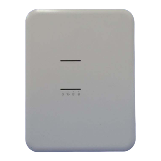
2. Appearance
Figure 1 HSC04 Appearance
2.1 Sockets
DC Jack: DC power voltage
9V, current 2A.
RJ-45 socket: HSC04 has
an Ethernet hub function
and is equipped with two
linked RJ-45 sockets.
2.2 Buttons
HSC04 has two buttons:
One reset button and a
connection button (next to
the RJ-45 socket).
■ Reset Button:
This button will reboot the system. The user can press this button when the
U-Net Gateway
User Manual
system is halting.
Note: HSC04 is equipped with internal battery power, which will be
automatically switched to when DC power is cut off. The device will still
be halting.
■ Connection Button:
M anually enable the bind function:
‧
Press the connection button once after the system is powered on.
M anually cancel the bind function:
‧
Press the connection button once when the system is in bind mode.
2.3. LED
- 1 -
LED1
LED2
LED3
Figure 2 HSC04Front View
LED4
Advertisement

Subscribe to Our Youtube Channel
Related Manuals for EVERSPRING HSC04-0

Summary of Contents for EVERSPRING HSC04-0
-
Page 1: User Manual
HSC04-0 U-Net Gateway User Manual system is halting. 1. Introduction Note: HSC04 is equipped with internal battery power, which will be automatically switched to when DC power is cut off. The device will still The HSC04 Gateway is a member of the U-Net series and is fully compatible be halting. - Page 2 3. Installation Definition of LED: LED1 Power LED2 Connection LED3 Network 1 LED4 Network 2 2.3.1 Power LED Green light: The power is on. R ed light: The Flash is writing data. R ed light flashes every 5 seconds: The system time is not synchronized ...
- Page 3 The connection LED on the HSC04 will stop flashing and turn on and off with ‧ S tick the double-sided tape to where you wish to place the batteries. A ttach batteries and insert power cables to complete installation. an interval of 2 seconds if binding was successful. ‧...
- Page 4 This device complies with Part 15 of the FCC Rules. Operation is subject to the interference to radio or television reception, which can be determined by turning the equipment following two conditions: (1) this device may not cause harmful interference, and (2) off and on, the user is encouraged to try to correct the interference by one of the following this device must accept any interference received, including interference that may cause undesired operation.
Need help?
Do you have a question about the HSC04-0 and is the answer not in the manual?
Questions and answers