Table of Contents
Advertisement
Advertisement
Table of Contents

Summary of Contents for Locus Energy LGate 120
- Page 1 LGate 120 Installation Guide Version 2.1...
-
Page 2: Table Of Contents
Table of Contents Important Product Information The LGate 120 Datalogger Revenue-Grade Monitoring Verifying Installation Accessing Data on the Device Inverter Direct Monitoring SMA Sunny Boy Power-One Aurora Kaco Blueplanet 02xi Fronius IG Plus Emerson SPV Eaton ISG PV Additional Device Monitoring... -
Page 3: Important Product Information
Disconnect the LGate 120 from the power source (both the breaker to the LGate and the AC disconnect) when servicing the product. The LGate is not intended for use in life-support applications. -
Page 4: The Lgate 120 Datalogger
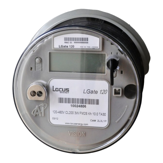
The LGate 120 Datalogger MAC ID Screen RS485 / Modbus Wires Ethernet Port RS485 / Modbus Wires (as shipped) -
Page 5: Revenue-Grade Monitoring
This type of monitoring works with single-phase inverters and power sources up to 200A. IMPORTANT: The LGate 120 does not ship with a meter socket included. For proper installation, the LGate 120 meter must be mounted in an installer-supplied meter socket that meets the following specifications: ... - Page 6 2. Connecting to the Internet The LGate 120 requires a network connection to communicate. The cell modem is the primary method of communication; if there is no cellular reception or using the cell modem is not an option, then use the secondary method, installing an Ethernet cable.
-
Page 7: Verifying Installation
2. Blinking slowly: The last data packet was not sent successfully and the cellular signal strength (if applicable) is weak. No phone icon: The LGate 120 is not connected to the network. For an Ethernet cable connection, double-check the pin-out on the Ethernet cable (see the FAQ section on page 31 for more information). - Page 8 5. Reading Verification Check that the energy (kWh), power (kW), and current (A) readings that cycle on the LED screen match the inverter output. If power readings are negative, the meter socket was installed backward. Verify that the inverter wires running through the meter socket go from line side to load side (top to bottom).
-
Page 9: Accessing Data On The Device
The ability to log into the LGate with a laptop to view configuration settings. Logging into the LGate 1. Reset the LGate 120 by turning off the AC disconnect and breaker to the LGate for 30 seconds, then back on again. - Page 10 (see below) Enabling the Ethernet Connection The LGate 120 comes preconfigured for a cellular connection. If the cellular option is not possible, enable the Ethernet Connection by selecting false in the Cell Mode drop-down menu and the Save Configuration button.
- Page 11 The LGate can be configured for either a dynamic (DHCP) or static IP address (on a LAN connection only). A dynamic IP address allows the router to assign the LGate 120 an IP address automatically. If using the cell modem, the LGate can only use a dynamic IP address. ...
-
Page 12: Inverter Direct Monitoring
Inverter Direct Monitoring Inverter direct monitoring is a monitoring feature that some companies purchase in addition to the core monitoring package. This feature should only be installed if it has been ordered for this particular project. If you are unsure if inverter direct monitoring has been purchased for this project, contact your company, lease provider, or program administrator. -
Page 13: Sma Sunny Boy
Extend the RS485 / Modbus wires as shown below. Crimp blue, brown, & inverter port 2 together Crimp blue-white, brown To first -white, & inverter port 7 LGate 120 inverter together Crimp green, shield & Shield signal inverter port 5... - Page 14 (Last/Only Inverter) Termination Termination Termination Jumper: not Jumper: not Jumper: Port A installed installed only LGate 120 Junction Last/Only Junction box for Inverter joining wires RS485 ‘Piggyback’ Shield wire twisted but Shield wire secured but card installed not terminated inside...
-
Page 15: Power-One Aurora
Extend the RS485 / Modbus wires as shown below. Crimp blue, brown, & inverter port +T/R together To first Crimp blue-white, brown LGate 120 inverter -white, & inverter port -T/R together Shield Crimp green, shield & signal inverter port RTN... - Page 16 Termination Termination Termination Switch: Turned Switch: Turned Switch: Turned to OFF to OFF to ON LGate 120 +T/R -T/R RTN +T/R -T/R RTN +T/R -T/R RTN Junction Junction box for joining wires Shield wire twisted but Shield wire secured but...
- Page 17 3. Terminating the Daisy Chain For the last or only inverter in the chain, turn the termination switch to ON. For all other inverters, turn the termination switch to OFF. Termination switch Last/Only Inverter Types of Communication Terminals Power-One inverters have several types of terminals for inverter direct communication: terminal blocks and comm jacks.
-
Page 18: Kaco Blueplanet 02Xi
Extend the RS485 / Modbus wires as shown below. Crimp blue, brown, & inverter port B together Crimp blue-white, brown To first -white, & inverter port A LGate 120 inverter together Crimp green, shield & Shield inverter port G together... - Page 19 Switches: Switches: sets of A, B, Turned to OFF Turned to OFF Turned to ON LGate 120 & G ports are inter- A B G A B G A B G A B G B G A B G Junction...
-
Page 20: Fronius Ig Plus
Termination Plug: Not Plug: Not Plug: installed installed Installed LGate 120 Junction Crimp blue to inverter blue Crimp blue-white to inverter blue-white Crimp brown to inverter green-white Crimp brown-white to inverter green Crimp orange to inverter brown-white Termination Plug in Last/Only Inverter... - Page 21 2. Configuring Inverters Fronius Interface A. Setting the IG Number 1. Wait 5 minutes for the inverter to start up; when done, the display will show PV production. 2. Press Menu to reach the main menu. 3. Scroll (press Up) until “SETUP” appears on the top and press Enter.
- Page 22 2. Configuring Inverters C. Setting the Baud Rate 1. Back in the password-protected menu, scroll to “IFP” and press Enter. 2. Scroll to “19200” and press Enter. 3. Go to AC Sync mode by selecting “ESC” twice and pressing Menu twice. D.
-
Page 23: Emerson Spv
Extend the RS485 / Modbus wires as shown below. Crimp blue, brown, & inverter port A together Crimp blue-white, brown To first -white, & inverter port B LGate 120 inverter together Crimp green, shield & Shield inverter port Gnd together... - Page 24 Junction box for inverter housing inverter housing joining wires Emerson SPV Inverter Junction Inverter #3 Inverter #1 Inverter #2 LGate 120 (Last/Only Inverter) Termination Termination Termination Resistor: Resistor: Resistor: Switched to OFF Switched to OFF Switched to ON...
- Page 25 3. Terminating the Daisy Chain For the last or only inverter in the chain, turn the termination switch to ON. For all other inverters, turn the termination switches to the left so ON is disabled. Termination Switch Emerson SPV Inverter...
-
Page 26: Eaton Isg Pv
Inverter #3 Inverter #1 Inverter #2 (Last Inverter) Termination Termination Termination Switch: Switch: Switch: Turned to OFF Turned to OFF Turned to ON LGate 120 T568B RJ45 RJ45 RJ45 RJ45 RJ45 RJ45 Junction Ethernet Port 1 Port 2 Port 1... - Page 27 2. Enabling RS485 Mode Set both dip switches on the left-hand side of the Modbus RTU to the “ON” position (down) to set the inverter to RS485 mode. Left-hand side dip switches turned to ON (down) RS485 Mode Enabled 3. Addressing the Inverters Note: Eaton inverters will automatically be assigned communication addresses by the LGate.
-
Page 28: Additional Device Monitoring
Extend the RS485 / Modbus wires as shown below. Crimp blue, brown, & EVSE port Data Line A together To first Crimp blue-white, brown LGate 120 inverter -white, & EVSE port Data Line B together Shield Crimp green, shield &... - Page 29 Shield wire secured but not terminated inside not terminated inside Junction box for EVSE housing EVSE housing joining wires Eaton Pow-R EVSE Junction LGate 120 Device #3 Device #2 Device #1 Modbus Modbus Modbus Address 3 Address 2 Address 1 2.
- Page 30 3. Setting the Baud Rate In order to set the Baud Rate to 9600, turn both dip switches 2 and 3 on SW1 to the “OFF” position (to the right). Dip Switches on SW1 4. Terminating the Daisy Chain If the Eaton Pow-R EVSE is the last device in a communication chain with at least 3 devices or the cable run from the LGate to a single device is greater than 100 feet, install a 150 ohm resistor between the data line wires at a connection point.
-
Page 31: Lgate 120 Faq
1. What is revenue-grade accuracy? 2. What is shielded twisted pair cable? 3. How should the LGate 120 be connected to the internet when not using the cell modem? 4. What are the minimum requirements for internet access when not using the cell modem? 5. - Page 32 ’dynamic reservation’, for the MAC ID of the LGate; also confirm that Port 80 is open outbound. B. Configure the LGate with a static IP address See page 10 for information on how to set the static IP address on the LGate 120.
- Page 33 It is not necessary to strip the wires. Ethernet Lights Locus Energy recommends using a CAT5 tester to make sure the Ethernet cable is live. Also check the Ethernet lights where the cable is plugged into the router or switch - both should be on or flashing (see image at right).
Need help?
Do you have a question about the LGate 120 and is the answer not in the manual?
Questions and answers