Table of Contents
Advertisement
Quick Links
Advertisement
Chapters
Table of Contents

Related Manuals for Kathrein K-BOW Platform 2

Summary of Contents for Kathrein K-BOW Platform 2
- Page 1 System Description INDOOR System Description K-BOW Platform 2 English...
-
Page 2: Table Of Contents
Contents About this Document Version and Version History Product and Manufacturer Markings Target Audience Scope of the Document Applicable Documents Abbreviations Disclaimer General Information IC Warnings FCC Warnings Intended Use System Overview Architecture Networking Layout Main Functionality WLAN Access (Wi-Fi) Glossary List of Diagrams List of Tables... -
Page 3: About This Document
0.91 March 2017 First release version 0.92 April 2017 Second release version Product and Manufacturer Item Description Product type Capacity distribution system: K-BOW platform 2 Manufacturer's address see last page Markings Symbol Symbol Description Description Symbole Symbole General hazard indication Danger due to laser light Avertissement général... -
Page 4: Target Audience
About this Document Signal words Mentions Description d’avertis- sement Danger Immediate risk of death or serious physical injury Risque immédiat de mort ou blessures corporelles graves Warning Possible risk of death or serious physical injury Avertis- Risque potentiel de mort ou blessures corporelles graves sement Caution Possible risk of slight or moderately severe physical injury... -
Page 5: Abbreviations
The information and documentation contained in this document is strictly confi dential and disclosed to the recipient only due to his/her particular relation to the KATHREIN-Werke KG. The content of this document is protected by copyright law. It is prohibited to exploit, divulge or use the document or any information contained therein, also in parts, without the explicit prior permission of KATHREIN-Werke KG. -
Page 6: General Information
General Information General Information IC Warnings Note This device complies with Industry Canada license-exempt RSS standard(s). Operation is subject to the following two conditions: (1) this device may not cause interference, and (2) this device must accept any interference, including interference that may cause undesired operation of the device. - Page 7 RF safety program Warning Changes or modifi cations to this equipment not expressly approved by KATHREIN could void the user’s authority to operate the equipment. At least two persons are required to carry 19" racks to avoid injuries. Warning Antenna gain should not exceed 7 dBi.
-
Page 8: Intended Use
General Information Intended Use The K-BOW system is a micro C-RAN solution to provide fl exible and effi ciently scalable coverage and capacity for multi-operator and multi-band scenarios using a common infrastructure. The system offers mobile radio single routing capabilities to support fl exible sectoring for network load balancing as well as individual signal power optimization of remote RF unit level. -
Page 9: System Overview
System Overview Architecture C-HUB E-HUB HPRU1 MIMO MIMO DDC/ FPGA Fibre FDD LTE Fibre DDC/ HPRU2 WCDMA DDC/ FPGA FPGA Fibre CAT5 CAT5 Down link WLAN Up link Fig. 1: System architecture 936.5465 0.92 9 of 20... -
Page 10: Networking Layout
System Overview Networking Layout K-BOW enables different networking layouts as shown in Fig. 2. The following applies: C-hub ● The C-hub supports a star network: ● The Master C-hub can connect to a maximum of 2 slave C-hubs simultaneously. ● A maximum of 5 slave devices including E-hub and RU cascade per fibre port of C-hub. E-hub ●... -
Page 11: Main Functionality
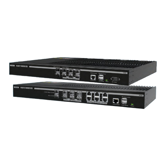
Main Functionality The system includes the access unit (C-hub), expansion unit (E-hub) and remote unit (RU). 3.3.1 C-Hub ● Frame radio-frequency signals from base stations of different base transceiver stations of different operators, and of different standards and frequency bands. ●... - Page 12 System Overview 3.3.3 E-Hub ● Receive the WLAN and small cell signals base station via 6 GigE Ethernet ports. ● Reframe with optical signal from the C-hub. ● Transmit the composite signal to next level E-hub and RU. Fig. 5: E-hub front view 3.3.4 HPRU...
-
Page 13: Wlan Access (Wi-Fi)
WLAN Access (Wi-Fi) Each E-hub has 6 electrical ports, GE1 to GE6, which support up to 6 LAN signals. LAN signals are input on the GE1 to GE6 ports and output from the corresponding OP1 to OP6 ports. The signals are then transmitted to the RUs via optical signals over optical fibre and output from the GE port on the RU. - Page 14 WLAN Access (Wi-Fi) AP 4-1 6 ports Ethernet switch 6 ports Ethernet switch Fibre RU4-1 Cat5 Cat5 Fibre RU4-2 Fibre Fibre E-HUB 1 E-HUB 4 Fibre RU4-3 AP 4-4 6 ports Ethernet switch Cat5 RU4-4 Fibre Fibre Fibre E-HUB 5 RU5-1-1 C-HUB AP 5- 1...
-
Page 15: Glossary
Glossary Abbreviation Description Analog to digital converter Access point Base transceiver station C-hub Central hub Carrier bundle Digital to analog converter Digital down convert Downlink Digital up convert E-hub Expansion hub Frequency division duplexing FPGA Field programmable gate array Global system for mobile communications HPRU High power remote unit Long term evolution... -
Page 16: List Of Diagrams
List of Diagrams List of Diagrams Fig. 1: System architecture Fig. 2: Networking layout Fig. 3: C-hub front view Fig. 4: C-hub module Fig. 5: E-hub front view Fig. 6: HPRU Fig. 7: WLAN access Fig. 8: Example for WLAN application List of Tables Tab. - Page 17 936.5465 0.92 17 of 20...
- Page 18 List of Diagrams 18 of 20 936.5465 0.92...
- Page 19 936.5465 0.92 19 of 20...
- Page 20 KATHREIN Solutions GmbH Anton-Kathrein-Straße 1 – 3 83004 Rosenheim, Germany Phone +49 8031 184-0 www.kathrein.com | k-bow@kathrein.de...
- Page 21 Start-up and Configuration INDOOR Start-up & Configuration Manual K-BOW Platform 2 English...
- Page 22 Contents About this Document Version and Version History Product and Manufacturer Markings Target Audience Scope of the Document Applicable Documents Abbreviations Disclaimer General Information General Safety Instructions Safety Requirements for the Installation Locations Electrical and Mechanical Safety IC Warnings FCC Warnings Intended Use K-BOW System Architecture Qualification of the Personnel...
- Page 23 Configure the Alarms Structure of the Web GUI Starting the Web GUI – Overview Master C-Hub Master/Slave E-Hub HPRU Glossary List of Diagrams List of Tables 936.5468 0.92 3 of 64...
-
Page 24: About This Document
0.91 March 2017 First release version 0.92 April 2017 Second release version Product and Manufacturer Item Description Product type Capacity distribution system: K-BOW platform 2 Manufacturer's address See last page Markings Symbol Symbol Description Description Symbole Symbole General hazard indication Danger due to laser light Avertissement général... -
Page 25: Target Audience
Signal words Mentions Description d’avertis- sement Danger Immediate risk of death or serious physical injury Risque immédiat de mort ou blessures corporelles graves Warning Possible risk of death or serious physical injury Avertis- Risque potentiel de mort ou blessures corporelles graves sement Caution Possible risk of slight or moderately severe physical injury... -
Page 26: Applicable Documents
The information and documentation contained in this document is strictly confi dential and disclosed to the recipient only due to his/her particular relation to the KATHREIN-Werke KG. The content of this document is protected by copyright law. It is prohibited to exploit, divulge or use the document or any information contained therein, also in parts, without the explicit prior permission of KATHREIN-Werke KG. -
Page 27: General Information
General Information General Safety Instructions ● Install the system only after you have read and understood the following documents: – This document – K-BOW Safety Instructions – K-BOW Setup Manual ● This document is an integral part of the K-BOW system. ●... - Page 28 General Information ● Protection against electrostatic discharge. Static electricity might harm sensitive components. To prevent this damage, discharge static electricity from your body before you touch equipment. You can also take the following steps to prevent damage that might result from electrostatic discharge. –...
-
Page 29: Safety Requirements For The Installation Locations
● The safety clearance between adjoining systems must be complied with. See the specifi cations of the companies operating the adjoining systems. ● If you use racks other than those recommended by Kathrein, make sure that the following conditions are satisfi ed: –... -
Page 30: Electrical And Mechanical Safety
General Information Electrical and Mechanical Safety Warning Risk of injury due to electricity. ● All K-BOW racks must be connected to a protective earthing conductor. ● It is recommended to earth the remote units to ensure their electromagnetic compatibility (EMC). ●... -
Page 31: Ic Warnings
IC Warnings Note This device complies with Industry Canada license-exempt RSS standard(s). Operation is subject to the following two conditions: (1) this device may not cause interference, and (2) this device must accept any interference, including interference that may cause undesired operation of the device. Le présent appareil est conforme aux CNR d'Industrie Canada applicables aux appareils radio exempts de licence. - Page 32 RF safety program Warning Changes or modifi cations to this equipment not expressly approved by KATHREIN could void the user’s authority to operate the equipment. At least two persons are required to carry 19" racks to avoid injuries. Warning Antenna gain should not exceed 7 dBi.
-
Page 33: Intended Use
Warning Risk of injury due to incomplete installation. ► The measures described in the Installation Manual (K-BOW Platform 2) must be fully completed before implementing the measures indicated in this document. ► Make sure the Installation Manual (K-BOW Platform 2) is present, so that, where necessary, the cabling can be checked and the safety instructions are available. -
Page 34: Powering Up The System And Checking The Status Leds
4. Check the status LEDs of the devices: ➯ Are the green SYS LEDs flashing slowly? ➯ Are the remote units' green OP LEDs flashing? For more information see the Installation Manual (K-BOW Platform 2), Section Cabling ▶ Interfaces. 14 of 64 936.5468 0.92... -
Page 35: Accessing The Devices' Web Interface (Web Gui)
Accessing the Devices' Web Interface (Web GUI) Topics Requirements, p. 15 Network Functionality, p. 15 Accessing the Web GUI Using Ethernet via C-Hub, p. 15 Accessing the Web GUI Using Ethernet via Slave Hubs/RUs, p. 17 Requirements The devices' web interface (web GUI) is compatible with common operating systems such as Apple MAC OS, Windows XP or higher. - Page 36 Accessing the Devices' Web Interface (Web GUI) Fig. 2: Browser address bar Fig. 1: Set TCP/IP properties master Fig. 3: Login dialogue 16 of 64 936.5468 0.92...
-
Page 37: Accessing The Web Gui Using Ethernet Via Slave Hubs/Rus
Accessing the Web GUI Using Ethernet via Slave Hubs/RUs ▶ ▶ 1. On the notebook, go to Control Panel Network Connections Local Area ▶ ▶ ▶ General. Connection Properties Internet Protocol (TCP/IP) Properties ① (Fig. 4). 2. Press the radio button Obtain an IP address automatically ②... -
Page 38: Accessing The Web Gui Using Wlan
Accessing the Devices' Web Interface (Web GUI) Fig. 6: Browser address bar Accessing the Web GUI using WLAN Structure of the Web GUI The structure of the Web GUI is very extensive and is therefore separately described in Section Structure of the Web GUI, p. 32. 18 of 64 936.5468 0.92... -
Page 39: Setting Up The C-Hub
Setting up the C-Hub Topics Check the Modules' Connection Status, p. 19 Set the Device Identification, p. 20 Set the SNMP and FTP Parameters, p. 21 Update the K-BOW System Software, p. 21 Configure the Band, p. 23 Configure the Input Power, p. 24 Configure the Band Gain, p. -
Page 40: Set The Device Identification
Setting up the C-Hub Set the Device Identification ▶ 1. Go to Settings Connectivity; see example in Fig. 8. ①ⓐ and enter the correct location in field ①ⓑ. 2. Select Device Location 4. Press to confirm. Fig. 8: Settings of the LAN connection (C-hub) 20 of 64 936.5468 0.92... -
Page 41: Set The Snmp And Ftp Parameters
5. Set the C-hub parameters ③. Update the K-BOW System Software If required, the K-BOW system software can be updated locally or via FTP. For details, see the document Operation and Maintenance (K-BOW Platform 2) 5.4.1 Update via FTP If FTP remote software upgrades shall be supported: ✔... - Page 42 Setting up the C-Hub Fig. 10: FTP parameters (C-hub) 22 of 64 936.5468 0.92...
-
Page 43: Configure The Band
Configure the Band According to the different base station operating frequency bands for each operator, the following must be set: ● The active RF modules for the C-hub and the active RF modules for the RUs with the corresponding frequency band ●... -
Page 44: Configure The Input Power
Setting up the C-Hub Fig. 11: Define carrier bundles Configure the Input Power The downlink input power of the C-hub is as follows: ● Nominal: 0 dBm ● Maximum: 15 dBm. Therefore, before accessing the RF signals, the signal power must be estimated. The downlink input power must be monitored with a spectrum analyser or read the downlink input power value from the combiners on the web GUI in order to set the downlink input power within the appropriate range. - Page 45 7. Only if, in Manual mode (step 3), the maximum input power exceeded 0 dBm: 2) 3) Set the attenuation per port (④) to reduce the input power to 0 dBm. 8. Set the channel's power offset value per port (⑤). 9.
-
Page 46: Configure The Band Gain
Setting up the C-Hub Configure the Band Gain 1. Open the master C-hubs web GUI as described under 4.3, p. 15/4.4, p. 26. ▶ 2. Go to Settings System Configurating. 3. Set the UL Gain Automatically Follow mode (②ⓐ in Fig. 13). 4. -
Page 47: Configure The Alarm
Configure the Alarm 5.8.1 Configure the Device Alarms Per default, all alarms are disabled. Tips To avoid false alarms, do not enable alarms of unconnected optical transceivers and channels. 1. Open the master C-hubs web GUI as described under 4.3, p. 15/4.4, p. 27. ▶... - Page 48 Setting up the C-Hub 5.8.2 Configure and Check Alarm Thresholds 1. Open the master C-hubs web GUI as described under 4.3, p. 15/4.4, p. 28. ▶ 2. Go to Alarms Alarm Thresholds. 3. Enter the threshold of the alarms as required; see ①ⓑ (Fig. 16). ②...
-
Page 49: Setting Up The E-Hub
Setting up the E-Hub Topics Query the Status of the E-Hubs, p. 29 Configure the Alarms, p. 29 Related topics Structure of the Web GUI, p. 32 Use Cases, p. 59 Query the Status of the E-Hubs ► Proceed as described under 5.1, p. 19 to query the status of the E-hubs. Configure the Alarms 1. -
Page 50: Setting Up The Remote Units
Setting up the Remote Units Setting up the Remote Units Topics Query the Status of the Remote Units, p. 30 Configure the Band Gain, p. 30 Configure the Alarms, p. 31 Related topics Structure of the Web GUI, p. 32 Use Cases, p. - Page 51 Configure the Alarms 1. Open the remote units' web-GUI as described under 4.4, p. 17. 2. Check and configure the alarms of the remote units. For this purpose, proceed as described for the C-hub under 5.8, p. 27 . 936.5468 0.92 31 of 64...
- Page 52 Structure of the Web GUI Structure of the Web GUI Topics Starting the Web GUI – Overview, p. 33 Master C-Hub, p. 33 Master/Slave E-Hub, p. 45 HPRU, p. 49 Starting the Web GUI – Overview ▶ When the web GUI was opened, it always shows the menu item Settings Topo(logy) (②...
- Page 53 ① Main menu for selecting the GUI pages ② Visualisation of the system topology: ● The device symbols indicate the device state as follows: green Device is connected and works without errors green + Device is connected and has errors warning symbol Device is not connected Double clicking a device symbol (ⓐ...
- Page 54 Structure of the Web GUI RW (read/ The parameter value is indicated. In addition, the parameter behaviour can write): be modified. As for alarm states, these are indicated using grey, green and red LEDs; see Section Alarm States below. As for the alarm severity, the following levels are available: Minor, Major, Warning, Critical.
- Page 55 8.2.1 Structure Overview Main menu Parameters are described in section ... Settings DAS Topo 8.2.2, p. 35 Band 8.2.3, p. 36 Configuration System 8.2.4, p. 37 Configuration System Status 8.2.5, p. 38 Combiners 8.2.6, p. 39 8.2.7, p. 40 Connectivity Alarms Device Alarms 8.2.8, p.
- Page 56 Structure of the Web GUI 8.2.3 Settings > Band Configuration Parameter Description Type Channel 1 Info check UL freq low, UL freq high Uplink (UL) limit frequencies DL freq low, DL freq high Downlink (DL) limit frequencies Carrier bundle x bandwidth Bandwidth of carrier bundle (CB) x Centre frequency of CB x UL Carrier bundle x UL centre frequency...
- Page 57 8.2.4 Settings > System Configuration Parameter Description Type Channel 1 UL attenuator Attenuation of the UL output signal of channel 1 to achieve a signal level of 0 dB DL attenuator Attenuation of the DL output signal of channel 1 to achieve a signal level of 0 dB Channel 1 ...
- Page 58 Structure of the Web GUI 8.2.5 Settings > System Status Parameter Description Type Channel 1 CB1 baseband input power CB2 baseband input power DL baseband input power UL baseband input power Channel 2 ... 4 See Channel 1 Master C-hub carrier configuration information CH1 CB0 –...
- Page 59 8.2.6 Settings > Combiners Parameter Description Type General Combiner att control mode The attenuation of the input Manual: power must be set manually using the parameters Port x attenuation value below. Auto: The attenuation is set automatically. Adjust interval Period of the input power level being below 0 dB, after which the attenuation will be raised (6/12/24 hours).
- Page 60 Structure of the Web GUI 8.2.7 Settings > LAN Connectivity Parameter Description Type General Vendor name Name of the company running the system; the name is fixed in the device's firmware Product model Product name; fixed in the device's firmware Serial number Serial number of the device Software edition...
- Page 61 8.2.8 Alarms > Device Alarms Parameter Description Type Alarm Power interruption alarm Battery failure alarm MOV alarm Open case alarm The housing of the device is open. Overtemperature alarm The of the device has exceeded the Overtemperature threshold. LO x unlocked alarm CH x DL ALC out-of-ctrl alarm OP x transceiver failure alarm External alarm x...
- Page 62 Structure of the Web GUI 8.2.9 Alarms > Downlink Input Power Alarms Parameter Description Type Channel 1 Port x under input-power alarm Port x over input-power alarm Channel 2 ... 4 See Channel 1 Tab. 8: Downlink input power alarm parameters C-hub 8.2.10 Alarms >...
- Page 63 8.2.12 Maintenance > Engineering Parameter Description Type Engineering info Data update time ARM CRC check FPGA CRC check Current C-hub software filename C-hub CRC check Current E-hub software filename E-hub CRC check Current HPRU software filename HPRU CRC check Digital panel information Maximum delay OP info OP x CPRI sync alarm...
- Page 64 Structure of the Web GUI 8.2.13 Maintenance > Factory Command Parameter Description Type Factory parameters Factory mode Factory mode password Tab. 12: Factory command parameters C-hub 44 of 64 936.5468 0.92...
- Page 65 Master/Slave E-Hub 8.3.1 Structure Overview Main menu Parameters are described in section ... Settings DAS Topo 8.3.2, p. 46 8.3.3, p. 46 Connectivity Alarms Alarm 8.3.4, p. 46 Alarm 8.3.5, p. 47 Threshold Maintenance Optical Module 8.3.6, p. 47 Information Engineering 8.3.7, p.
- Page 66 Structure of the Web GUI 8.3.2 Settings > DAS Topo DAS Topo tab is described in Section 7.1, p. 33. 8.3.3 Settings > LAN Connectivity Parameter Description Type General Vendor name See description under 8.2.7, p. 40. – Product model ditto –...
- Page 67 8.3.5 Alarms > Alarm Thresholds Parameter Description Type Alarm thresholds Overtemperature threshold See description under 8.2.10, p. 42. – Tab. 15: Alarm threshold parameters E-hub 8.3.6 Maintenance > Optical Module Information Parameter Description Type Port 1 Tx power See description under 8.2.11, p. 42. –...
- Page 68 Structure of the Web GUI Hardware reset ditto – Software reset ditto – Alarm initialization ditto – Alarm mode select ditto – Tab. 17: Engineering parameters E-hub 8.3.8 Maintenance > Factory Command Parameter Description Type Factory parameters Factory mode See description under 8.2.13, p. 44. –...
- Page 69 HPRU 8.4.1 Structure Overview Main menu Parameters are described in section ... Settings DAS Topo 8.4.2, p. 50 System 8.4.3, p. 50 Configuration System Status 8.4.4, p. 51 Actual Gain 8.4.5, p. 51 8.4.6, p. 52 Connectivity Alarms Alarm 8.4.7, p. 53 Alarm 8.4.8, p.
- Page 70 Structure of the Web GUI 8.4.2 Settings > DAS Topo DAS Topo tab is described in Section 7.1, p. 33. 8.4.3 Settings > System Configuration Parameter Description Type Channel 1 RF signal switch A RF signal is fed to the HPRU RF output. No signal is fed to the HPRU RF output.
- Page 71 8.4.4 Settings > System Status Parameter Description Type Channel 1 UL frequ low UL frequ high DL frequ low DL frequ high UL baseband input power DL baseband output power UL input power DL output power VSWR Channel 2 See Channel 1 Channel map (HPRU C-hub) Channel map 1 Channel map 1...
- Page 72 Structure of the Web GUI 8.4.6 Settings > LAN Connectivity Parameter Description Type General Vendor name See description under 8.2.7, p. 40. – Product model ditto – Serial number ditto – Software edition ditto – FPGA edition ditto – Device ID ditto –...
- Page 73 8.4.7 Alarms > Alarm Parameter Description Type Alarm Power interruption alarm See description under 8.2.8, p. 41. – MOV alarm ditto – Open case alarm ditto – Overtemperature alarm ditto – LO x unlocked alarm ditto – CH x UL ALC out-of-ctrl alarm CH x VSWR alarm OP slave transceiver-failure alarm OP master transceiver-failure alarm...
- Page 74 Structure of the Web GUI 8.4.9 Maintenance > Optical Module Information Parameter Description Type Slave port Tx power See description under 8.2.11, p. 42. – Rx power ditto – Tx wavelength ditto – Master port Tx power ditto – Rx power ditto –...
- Page 75 8.4.10 Maintenance > Engineering Parameter Description Type Engineering info Data update time See description under 8.2.12, p. 43. – ARM CRC check ditto – FPGA CRC check ditto – HPRU CRC check ditto – DPD switch CH x DPD switch OP info OP slave CPRI sync alarm See description under 8.2.12, p.
- Page 76 Structure of the Web GUI 8.4.12 Capacity Management > Service Configuration Parameter Description Type Capacity allocation switch Capacity allocation switch Master C-hub carrier configuration information CH x CB0–CB1 (BW/UL/DL) Slave C-hub 1 carrier configuration information CH x CB0–CB1 (BW/UL/DL) See Master C-hub carrier configuration information –...
- Page 77 Glossary Abbreviation Description Analog to digital converter Access point Base transceiver station C-hub Central hub Carrier bundle Digital to analog converter Digital down convert Downlink Digital up convert E-hub Expansion hub Frequency division duplexing FPGA Field programmable gate array Global system for mobile communications HPRU High power remote unit Long term evolution...
- Page 78 58 of 64 936.5468 0.92...
- Page 79 936.5468 0.92 59 of 64...
- Page 80 60 of 64 936.5468 0.92...
- Page 81 936.5468 0.92 61 of 64...
- Page 82 List of Diagrams List of Diagrams Fig. 1: Set TCP/IP properties master Fig. 2: Browser address bar Fig. 3: Login dialogue Fig. 4: Set TCP/IP properties slaves Fig. 5: Check TCP/IP properties slaves Fig. 6: Browser address bar Fig. 7: Web GUI of master C-hub Fig.
- Page 83 List of Tables Tab. 1: Symbols and signal words Tab. 2: Band configuration parameters C-hub Tab. 3: System configuration parameters C-hub Tab. 4: System status parameters C-hub Tab. 5: Combiner parameters C-hub Tab. 6: LAN connectivity parameters C-hub Tab. 7: Device alarm parameters C-hub Tab.
- Page 84 KATHREIN Solutions GmbH Anton-Kathrein-Straße 1 – 3 83004 Rosenheim, Germany Phone +49 8031 184-0 www.kathrein.com | k-bow@kathrein.de...
- Page 85 Installation Manual INDOOR Installation Manual K-BOW Platform 2 English...
- Page 86 Contents About this Document Version and Version History Product and Manufacturer Markings Target Audience Scope of the Document Applicable Documents Abbreviations Disclaimer General Information General Safety Instructions Safety Requirements for the Installation Locations Installation and Operation Electrical and Mechanical Safety IC Warnings FCC Warnings Intended Use...
- Page 87 List of Diagrams List of Tables 936.5467 0.92 3 of 50...
-
Page 88: About This Document
0.91 March 2017 First release version 0.92 April 2017 Second release version Product and Manufacturer Item Description Product type Capacity distribution system: K-BOW platform 2 Manufacturer's address see last page Markings Symbol Symbol Description Description Symbole Symbole General hazard indication Danger due to laser light Avertissement général... -
Page 89: Target Audience
Signal words Mentions Description d’avertis- sement Danger Immediate risk of death or serious physical injury Risque immédiat de mort ou blessures corporelles graves Warning Possible risk of death or serious physical injury Avertis- Risque potentiel de mort ou blessures corporelles graves sement Caution Possible risk of slight or moderately severe physical injury... -
Page 90: Applicable Documents
The information and documentation contained in this document is strictly confi dential and disclosed to the recipient only due to his/her particular relation to the KATHREIN-Werke KG. The content of this document is protected by copyright law. It is prohibited to exploit, divulge or use the document or any information contained therein, also in parts, without the explicit prior permission of KATHREIN-Werke KG. -
Page 91: General Information
General Information General Safety Instructions ● This document is an integral part of the K-BOW system platform 2. ● Read all K-BOW documentation completely, especially – before installing a K-BOW system platform 2, – before the fi rst start-up, – before operating a system, –... - Page 92 General Information ● Field replacement is permitted. It is recommend to power off the device before replacing. ● Please use Shielded Twisted Pair (STP) for WLAN application. ● Protect against electrostatic discharge. Static electricity might harm sensitive components. To prevent this damage, discharge static electricity from your body before you touch equipment.
-
Page 93: Safety Requirements For The Installation Locations
● The safety clearance between adjoining systems must be complied with. See the specifi cations of the companies operating the adjoining systems. ● If you use racks other than those recommended by Kathrein, make sure that the following conditions are satisfi ed: –... -
Page 94: Installation And Operation
General Information 2.2.3 Installation Location of Remote Units and Antennas The installation location of remote units and antennas must satisfy the following requirements: ● When installing remote units and antennas, the Installation Manual (K-BOW Platform 2) has to be considered. Caution Risk of injury due to non-ionising radiation radio frequency When installing the antennas, pay attention to the required distance of at least 205 cm between antennas and human bodies during normal operation according to ETSI EN 62311. -
Page 95: Electrical And Mechanical Safety
Electrical and Mechanical Safety Warning Risk of injury due to electricity. ● All K-BOW racks must be connected to a protective earthing conductor. ● Do not connect system components to the power supply during installation. Connection to the power supply must be performed by a trained, qualifi ed and authorised specialist. -
Page 96: Ic Warnings
General Information Notice Risk of damage to property due to electricity. ● Install the C-hub and E-hub in a closed and locked rack to prevent unauthorised access and any impact due to ESD. ● It is recommended to earth the remote units to ensure their electromagnetic compatibility (EMC). -
Page 97: Fcc Warnings
RF safety program Warning Changes or modifi cations to this equipment not expressly approved by KATHREIN could void the user’s authority to operate the equipment. At least two persons are required to carry 19" racks to avoid injuries. Warning Antenna gain should not exceed 7 dBi. -
Page 98: Intended Use
General Information Warning To comply with FCC RF exposure compliance requirements, each individual antenna used for this transmitter must be installed to provide a separation distance greater than 205 cm or more from all persons during normal operation and must not be co-located with any other antenna for meeting RF exposure requirements. - Page 99 936.5467 0.92 15 of 50...
-
Page 100: Scope Of Delivery
General Information Scope of Delivery Fig. 1: Scope of delivery 16 of 50 936.5467 0.92... - Page 101 ① C-hub ⓐ Mounting and cabling accessories for C-hub ● ● ● 4 × screw M6×16 8 × screw M3×16 2 × 19" mounting bracket ● ● ● 1 × Ethernet Cat 5 cable, 1 × ground wire, 2 m 1 ×...
-
Page 102: Preconditions And Requirements
● all points on the checklist Ready for Installation must have been satisfied. The template for this checklist is provided by Kathrein during the installation training. ● the handover point for the BTS signals must have been specified and be available;... -
Page 103: Requirements For The Installation Location
Requirements for the Installation Location 3.2.1 General ● Install the K-BOW system indoors only and as a stationary system in weather-protected and temperature-controlled locations. ● Comply with the permissible ambient conditions stated in the data sheets of the K-BOW components. ●... - Page 104 ● The safety clearance between adjoining systems must be complied with. See the specifi cations of the companies operating the adjoining systems. ● If you use racks other than those recommended by Kathrein, make sure that the following conditions are satisfi ed: –...
-
Page 105: Required Material For Installation
Required Material for Installation 3.3.1 Required Tools Phillips screwdriver For wall mounting only: M3 and M6 Drilling machine and drills Allen wrench T5 Combination spanner 17 mm Drills have to be provided according to the material of the mounting surface and the mounting accessories used. - Page 106 Preconditions and Requirements 3.3.2 Required Mounting Accessories Mounting Accessories Included in Delivery The mounting accessories included in delivery are described under 2.9, p. 16. Mounting Accessories Not Included in Delivery Wall-mounting accessories are not included in delivery. Only exception: the expansion bolts for mounting the HPRU. e.g.
-
Page 107: Installing The C-Hub
The rear panel and side panels must contain lockable access doors. The doors must extend over the entire rear and side panels. ● If you use racks which are not recommended by Kathrein, these racks must comply with the following specifications: –... -
Page 108: Power Distribution Bars
Installing the C-Hub Power Distribution Bars Notice Risk of reduced operational reliability because of power failure. Make sure that the 230 VAC power supply to the K-BOW system rack satisfies the following conditions: ● 3 or 6 power distribution modules are used in order to ensure redundancy of the power supply;... - Page 109 Power distribution bar ① mounted Plugs for power connection: ① is Fig. 6: Fig. 7: for red circuit, ② for black circuit on the left-hand traverse 936.5467 0.92 25 of 50...
-
Page 110: Mounting C-Hub In Rack And Connecting Power And Ground
Installing the C-Hub Mounting C-Hub in Rack and Connecting Power and Ground ✔ The 19" rack is mounted according to the requirements for the installation location; see 3.2.2, p. 19. ✔ The mounting accessories and tools are available as specified in 3.3, p. 21 . Attach handle to C-hub ►... - Page 111 Connect power and ground cable to C-hub 1. Connect and lock the power cable at the C-hub rear side (Fig. 12). 2. Connect and screw the ground wire at the C-hub rear side (Fig. 13). not included in delivery Fig. 12: Connect power cable at rear side Fig.
-
Page 112: Mounting C-Hub On Wall And Connecting Power And Ground
Installing the C-Hub Mounting C-Hub on Wall and Connecting Power and Ground ✔ The installation location complies with the specification given in 3.2.3, p. 20. ✔ The mounting accessories and tools are available as specified in 3.3, p. 21 . Attach handle to C-hub ►... -
Page 113: Installing The E-Hub
Connect power and ground cable to C-hub 1. Connect and lock the power cable at the C-hub rear side; see Fig. 17. 2. Connect and screw the ground wire at the C-hub rear side; see Fig. 18. not included in delivery Fig. -
Page 114: Installing The Hpru
Installing the HPRU Installing the HPRU Mounting HPRU on Wall ✔ The installation location complies with the specification given in 3.2.3, p. 20. ✔ The mounting accessories and tools are available as specified in 3.3, p. 21 . Attach handle and mounting bracket Ⓐ to the HPRU 1. - Page 115 Fig. 21: Marking mounting holes for Fig. 22: Prepare expansion bolts for bracket Ⓑ bracket Ⓑ Fig. 23: Mounting accessories for bracket Ⓑ Fig. 24: Bracket Ⓑ mounted 936.5467 0.92 31 of 50...
- Page 116 Installing the HPRU Attach HPRU to bracket Ⓑ 1. Hook the HPRU to the bracket Ⓑ (① in Fig. 25). 2. Place the M10 mm flat/spring washers and the nuts on the bracket Ⓑ bolts in the correct order (② in Fig. 25). 3.
-
Page 117: Connecting Power And Ground Cable To Hpru
Connecting Power and Ground Cable to HPRU 1. Connect and lock the power cable at the HPRU rear side; see Fig. 28. 2. Connect and screw the ground wire at the HPRU rear side; see Fig. 29. not included in delivery Fig. -
Page 118: Cabling
Cabling Cabling Interfaces 7.1.1 C-Hub (Master and Slave) Front Side Fig. 30: Interfaces at the C-hub front side Connector Function ① Master C-hub: Connects to E-hub or RU at next lower level optical port with SFP Slave C-hub: Connects to Master C-hub module 1) 2) 3) ②... - Page 119 Rear Side ⇐ Port ⇐ Module Fig. 31: Interfaces at the C-hub rear side Connector Function ① ④ F-SMA Module 1 – 4 TRX ports, connect to BTS – ⑤ Connects mains cable ⑥ Connects ground wire Included in delivery For optical cables with duplex LC connector Via the optical connection, user and control data are transmitted.
- Page 120 Cabling 7.1.2 E-Hub Front Side Fig. 32: Interfaces at the E-hub front side Connector Function ① ⑥ optical port Connects to RU – with SFP 1) 2) 3) module ⑦ ⑫ RJ45 Ethernet ports 1 – 6 for WLAN signals or S1 signals input –...
- Page 121 Rear Side Fig. 33: Interfaces at the E-hub rear side Connector Function ① Connects mains cable ② Connects ground wire Included in delivery For optical cables with duplex LC connector Via the optical connection, user and control data are transmitted. 936.5467 0.92 37 of 50...
- Page 122 Cabling 7.1.3 HPRU Connector Side Fig. 34: Interfaces at the HPRU connector side Connector Function ① optical port Connects to a master C-hub, an E-hub or to a RU at next higher with SFP level module 1) 2) 3) ② LED, indicates the status of ①: green: ok;...
-
Page 123: Cabling
● For more information about the cabling of the remote units, see the document Instal- lation Manual (K-BOW Platform 2) and the installation instructions for the remote units. The permissible bending radii can be found in the cable data sheets. - Page 124 Cabling 7.2.2 Cabling the Fibre Optics Connections ✔ The fibre optic cables for connecting the hubs and RUs are provided. 1. Carefully insert the required SFP modules. In doing so, observe the colour labelling of the SFP modules indicated in Fig. 35. 2.
- Page 125 7.2.3 Cabling the Coaxial Connections ✔ The coaxial cables for connecting the BTS and the C-hub (via the load unit) are provided. ► Install the required coaxial connections. Fig. 36 gives an overview. Control Bus in/out 48 V Rx/Tx Rx/Tx Rx/Tx Load Port 2...
- Page 126 Cabling 7.2.4 Cabling the Power Supply ► Install the required power supply connections. Fig. 37 gives an overview. Control Bus in/out 48 V Rx/Tx Rx/Tx Rx/Tx Load BS Rx/Tx Port 2 BS Rx/Tx Port 4 BS Rx/Tx Port 6 unit Port 1 BS Rx/Tx Port 3...
-
Page 127: Helpful Hints For Cabling
Helpful Hints for Cabling 7.3.1 Measuring Fibre Optic Cables After cabling with fibre optic cables that have been assembled on site, it is necessary to check whether the fibre optic cables are still functioning. The purpose of this is to detect joints, for instance at plug connections, and damaged cables. -
Page 128: System Documentation
System Documentation System Documentation It is suggested to store the system documentation in a document drawer in the main rack. The system documentation consists of the following documents: Documents Description Special instructions Floor plans Describes the planned routing of If the actual routing path differs from all cables not within the racks;... -
Page 129: Glossary
Glossary Abbreviation Description Analog to digital converter Access point Base transceiver station C-hub Central hub Carrier bundle Digital to analog converter Digital down convert Downlink Digital up convert E-hub Expansion hub Frequency division duplexing FPGA Field programmable gate array Global system for mobile communications HPRU High power remote unit Long term evolution... - Page 130 46 of 50 936.5467 0.92...
- Page 131 936.5467 0.92 47 of 50...
- Page 132 List of Diagrams List of Diagrams Fig. 1: Scope of delivery Fig. 2: Example of a handover point for the BTS signals at a c-rail Fig. 3: Example of a handover point for the BTS signals with individual loads with short patch cables at a c-rail Clearance Ⓐ...
- Page 133 List of Tables Tab. 1: Symbols and signal words Tab. 2: Storage of the system documentation 936.5467 0.92 49 of 50...
- Page 134 KATHREIN Solutions GmbH Anton-Kathrein-Straße 1 – 3 83004 Rosenheim, Germany Phone +49 8031 184-0 www.kathrein.com | k-bow@kathrein.de...
Need help?
Do you have a question about the K-BOW Platform 2 and is the answer not in the manual?
Questions and answers