
Subscribe to Our Youtube Channel
Related Manuals for NANOTEC ELECTRONIC SMCI35


Summary of Contents for NANOTEC ELECTRONIC SMCI35
- Page 1 Technical Manual Stepper controller SMCI35 NANOTEC ELECTRONIC GmbH & Co. KG Tel. +49 (0)89-900 686-0 Gewerbestraße 11 +49 (0)89-900 686-50 D-85652 Landsham near Munich, Germany info@nanotec.de...
- Page 2 Technical manual SMCI35 Editorial Editorial © 2010 ® Nanotec Electronic GmbH & Co. KG Gewerbestraße 11 D-85652 Landsham / Pliening, Germany Tel.: +49 (0)89-900 686-0 Fax: +49 (0)89-900 686-50 Internet: www.nanotec.de All rights reserved! MS-Windows 2000/XP/Vista are registered trademarks of Microsoft Corporation.
- Page 3 Technical manual SMCI35 About this manual About this manual Target group This technical manual is aimed at designers and developers who need to operate a Nanotecâ stepper motor without much experience in stepper motor technology. Important information This technical manual must be carefully read before installation and commissioning of the stepper motor control.
-
Page 4: Table Of Contents
Technical manual SMCI35 Contents Contents Overview ..........................5 Connection and commissioning ..................7 Connection diagram ....................... 7 Commissioning........................9 Connections and circuits ....................11 Overview ..........................11 Inputs and outputs: connector X4 and X5................12 Encoder connection: Connector X2 ..................14 Stepping motor and power supply: connector X3 .............. -
Page 5: Overview
Overview Overview Introduction The stepper motor control SMCI35 is an extremely compact and cost-effective constant current power output stage with integrated Closed-Loop current control. Due to the great capacity and functions available, it offers designers and developers a rapid and simple method of resolving numerous drive requirements with less programming effort. - Page 6 Technical manual SMCI35 Overview With the integrated NanoJ programming language based on the Java standard, complete sequencing programs can be implemented that can be run autonomously without a superordinate controller. The programs can be created, compiled directly and written to the controller with the free NanoJEasy editor.
-
Page 7: Connection And Commissioning
Technical manual SMCI35 Connection and commissioning Connection and commissioning Connection diagram Introduction To operate a stepper motor with the SMCI35 stepper motor control, the wiring must be implemented according to the following connection diagram. Issue: V 1.1 - 05.03.2010... - Page 8 Technical manual SMCI35 Connection and commissioning Connection diagram SMCI35 Issue: V 1.1 - 05.03.2010...
-
Page 9: Commissioning
This section describes the main first steps you need to take to be able to quickly begin working with the SMCI35 if you are using the NanoPro software from a PC. You will find more detailed information in the separate NanoPro manual. - Page 10 Select the "Communication" tab. In the "Port" field, select the COM port to which The number of the COM the SMCI35 is connected. port to which the controller is connected can be found in the device manager of your Windows PC. (System control/system/hardware).
-
Page 11: Connections And Circuits
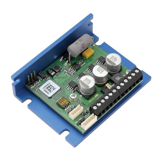
Technical manual SMCI35 Connections and circuits Connections and circuits Overview Plug connections The controller has the following connectors: X1: RS232 interface X2: Encoder interface X3: Stepper motor and power supply connector X4 and X5: Inputs and outputs Configuration The following figure shows the configuration of the connectors on the printed circuit board. -
Page 12: Inputs And Outputs: Connector X4 And X5
Technical manual SMCI35 Connections and circuits Inputs and outputs: connector X4 and X5 Introduction An overview of the assignments can be found in the wiring diagram in Section 2.1). This section looks in detail at the assignments, functions and circuits of connectors X4 and X5. - Page 13 Technical manual SMCI35 Connections and circuits Signal states at the outputs The following table shows the possible signal states at the outputs 1 to 3: Signal states Meaning Output 3 Output 2 Output 1 Rotation monitoring (error) or limit switch Motor idle (waiting for new command).
-
Page 14: Encoder Connection: Connector X2
Technical manual SMCI35 Connections and circuits Encoder connection: Connector X2 Optional encoder An optional encoder can be connected to the stepper motor control. By default, the closed-loop control for a three-channel encoder is set up with 500 pulses/revolution in a 1.8° stepper motor. With an 0.9° stepper motor, you should use an encoder with 1000 pulses/revolution to achieve the same control quality. -
Page 15: Stepping Motor And Power Supply: Connector X3
Technical manual SMCI35 Connections and circuits Stepping motor and power supply: connector X3 3.4.1 Pin assignment Pin no. Name Observations See also data sheet of connected stepper motor (color code of 4 wires). Switch on the operating voltage (+24 V DC ... +48 V DC) Earth (0 V) 3.4.2... - Page 16 Technical manual SMCI35 Connections and circuits Motor with 6 or 8 connections If you are using a motor with 6 or 8 connections, you need to connect the windings. The following figure shows four wiring diagrams for motors with 6 or 8 connections (page from the Nanotec product catalogue).
-
Page 17: Power Supply Connection
Power supply connection Permissible operating voltage The permissible operating voltage for the SMCI35 stepper motor control lies between +24 and +48 V DC; it must not exceed 50 V or fall below 21 V . A charging condenser with minimum 4700 µF (10000 µF) must be provided for the operating voltage to prevent exceeding the permissible operating voltage (e.g. -
Page 18: Rs232 Interface: Connector X1
Technical manual SMCI35 Connections and circuits RS232 interface: connector X1 Introduction The controller has a serial TTL RS232 interface (3.3 V) for connecting to a PC. Converter cable Use the converter cable ZK-RS232-USB-3.3V for connection to the USB port of the PC. -
Page 19: Operating Modes
Technical manual SMCI35 Operating modes Operating modes Introduction Depending on the drive profile, the motor can be operated using a total of 14 different operation modes. Due to the good performance and variety of functions available, they offer designers and developers a rapid and simple method of resolving numerous drive requirements with less programming effort. - Page 20 Technical manual SMCI35 Operating modes Operation mode Application Clock direction mode, left Use this mode when you wish to operate the motor with a superordinate controller (e.g. CNC controller). Clock direction mode, right In the clock direction mode, the motor is operated via...
-
Page 21: Troubleshooting
Click on the <Yes> button to stop the the controller during the output travel profile. of a travel profile. The SMCI35 switches back to the "Ready" state. The data can then be resent to the controller. Transmission Data transmission to the... -
Page 22: Technical Data
Technical manual SMCI35 Technical data Technical data Electrical connections Operating voltage V DC 24 V to 48 V ±4% Max. phase current Adjustable up to max. 6 A/phase Continuous current 4 A/phase Current drop Adjustable 0 to 150% of phase current Port TTL-RS232 (3.3 V) - Page 23 SMCI35 dimensions A complete set of datasheets is available for downloading at www.nanotec.de. Connectors The following connectors are available on the SMCI35: • Connector X1: pin connector 2.54 • Connector X2 and X5: JST-ZH • Connector X3 and X4: RIA 059...
-
Page 24: Index
Technical manual SMCI35 Index Index Accessories for voltage supply.....17 NanoJ.............. 6 Closed-Loop current control ......5 Operating modes .......... 19 Commissioning ..........9 Operating voltage.......... 17 Connection diagram ........8 Output circuits ..........13 Outputs ............12 dspDrive............5 Pin assignment connector X1 ....... 18 Pin assignment connector X2 .......
Need help?
Do you have a question about the SMCI35 and is the answer not in the manual?
Questions and answers