Table of Contents
Advertisement
Quick Links
Advertisement
Table of Contents

Related Manuals for Michell Instruments HygroCal100

Summary of Contents for Michell Instruments HygroCal100
- Page 1 HygroCal100 Humidity Validator User’s Manual 97500 Issue 3 January 2018...
- Page 2 Please fi ll out the form(s) below for each instrument that has been purchased. Use this information when contacting Michell Instruments for service purposes. Instrument Code Serial Number Invoice Date Location of Instrument Tag No Instrument Code Serial Number Invoice Date...
- Page 3 © 2016 Michell Instruments This document is the property of Michell Instruments Ltd. and may not be copied or otherwise reproduced, communicated in any way to third parties, nor stored in any Data Processing System without the express written authorization of Michell Instruments Ltd.
-
Page 4: Table Of Contents
HygroCal100 User’s Manual Contents Safety ..........................vii Electrical Safety ......................vii Toxic Materials ......................vii Repair and Maintenance ....................vii Calibration ........................vii Safety Conformity ....................... vii Abbreviations ........................viii Warnings .......................... viii INTRODUCTION ....................1 Operating Principle ..................... 1 INSTALLATION ....................2 Unpacking ...................... - Page 5 Table 1 Operation Mode Screen Parameters ............15 Table 2 Probe Setup Screen Parameters ..............16 Table 3 HygroCal100 Logging Screen Parameters ............ 18 Table 4 RH Reference Setup Screen Parameters ............20 Table 5 Display Settings Screen Parameters ............21 Table 6 Clock Settings Screen Parameters ...............
- Page 6 Operation Mode Screen ................15 Figure 16 Probe Setup Screen ..................16 Figure 17 Program Calibration Routine Screen ............17 Figure 18 HygroCal100 Logging Screen ..............18 Figure 19 Log Files Screen ..................19 Figure 20 RH Reference Setup Screen ...............20 Figure 21 System Settings Screen ................21 Figure 22 Display Settings Screen ................21...
-
Page 7: Safety
The recommended calibration interval for the HS3 control sensor is one year, unless otherwise specifi ed by Michell Instruments Ltd. The instrument should be returned to the manufacturer, Michell Instruments, or one of their accredited service agents for re-calibration (go to www.michell.com for contact information). -
Page 8: Abbreviations
HygroCal100 User’s Manual Abbreviations The following abbreviations may or may not be used in this manual: alternating current pressure unit (atmosphere) pressure unit (=100 kP or 0.987 atm) °C degrees Celsius °F degrees Fahrenheit common dew point European Union Human Machine Interface... -
Page 9: Introduction
fl owing through the saturator, moisture is added to almost completely saturate it at the prevailing temperature. A Michell Instruments' Hygrosmart 3 control sensor is installed inside the calibration chamber, continually measuring the temperature and relative humidity inside. When a... -
Page 10: Installation
HygroCal100 User’s Manual INSTALLATION Unpacking The HygroCal100 will be supplied in a carry case (if this option was selected) or in a cardboard box. If the HygroCal was ordered with a carry case: Remove the carry case from the packing box. -
Page 11: Operating Requirements
(optional) carry case with any other spare port adaptors ordered. Operating Requirements 2.2.1 Environmental Requirements It is important to operate the HygroCal100 within the following environmental conditions: Minimum operating temperature +5°C (+41°F) Maximum operating temperature +40°C (+104°F) Maximum relative humidity 2.2.2... -
Page 12: Exterior Layout
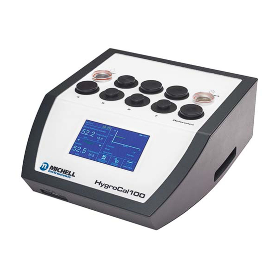
INSTALLATION HygroCal100 User’s Manual Exterior Layout The controls, indicators and connectors associated with the HygroCal100 are located on the front, top and rear panels of the device. Front Panel Front Panel Figure 1 Accepts a USB memory device for the transfer of logged USB port data (see Section 3.4.4.4 for instructions on how to... -
Page 13: Figure 2 Top Panel
HygroCal100 User’s Manual INSTALLATION Top Panel Figure 2 Top Panel Contains a diffuser and distilled water used to humidify the Saturator reservoir air in the chamber (see Section 4.2 for instructions on how to refi ll the saturator). Used to mount probes under test into the chamber (see Probe ports Section 2.5.1 for instructions on how to install port adaptors... -
Page 14: Figure 3 Rear Panel
INSTALLATION HygroCal100 User’s Manual Rear Panel Rear Panel Figure 3 Connections for probes under test (see Section 2.5.1 for Probe input connections instructions on how to connect probes). Allows the HygroCal to be connected to a PC, outputting USB communications... -
Page 15: Rear Panel Layout
HygroCal100 User’s Manual INSTALLATION Rear Panel Layout These tasks should only be undertaken by qualifi ed personnel. Connections to the rear panel of the chamber are explained in the following sections: 2.4.1 Probe Input Connections Seven 8-pin connectors are provided to allow connection of probes under test. Probes with a voltage or current input can be connected. -
Page 16: Usb Communications Port
INSTALLATION HygroCal100 User’s Manual 2.4.2 USB Communications Port The USB type-B connector on the rear panel allows the HygroCal to be connected to a PC, outputting the relative humidity and temperature values of both the reference probes and the probes under test. -
Page 17: Power Adaptor Input
HygroCal100 User’s Manual INSTALLATION 2.4.4 Power Adaptor Input The DC power connector is a push fi t into the power input socket, as shown in Figure 7 . The method of connection is as follows: Ensure that both ends of the power cable are potential free, i.e. not connected to an AC power supply. -
Page 18: Desiccant Reservoir
Replace the lid. Removing water: Power off the HygroCal100 and place on a fl at, stable surface with the back panel facing down. Remove the saturator lid and use the syringe provided to remove the water from the reservoir. -
Page 19: Operation
OPERATION OPERATION Once fi lled with water and desiccant, the HygroCal100 is ready for operation. This section describes both the general operation of the chamber and the method of setting it up and changing the default parameters (see Section 3.4.5.4) should this become necessary. -
Page 20: Main Screen Layout
OPERATION HygroCal100 User’s Manual Main Screen Layout % RH SET POINT POWER STATUS STABILITY GRAPH REFERENCE READOUT OPERATIONAL STATUS DISPLAY PROBE SELECTION PROBE READOUT SYSTEM CALIBRATION TABLE VIEW SETTINGS SETTINGS Main Screen Layout Figure 12 Indicates the target RH set point. See Section 3.4.1 Relative Humidity Set Point for additional information. -
Page 21: Menu Structure
HygroCal100 User’s Manual OPERATION Menu Structure Cal Settings Mode Probes Program Logging Ref Setup Operation Displayed Output Signal Status Mode Reference Port Temp. Zero Duration Filename Selection External Temp. Span Interval Input External Temperature Log Files Zero External Temperature Span... -
Page 22: Current Set Point
OPERATION HygroCal100 User’s Manual 3.4.1 Current Set Point The target relative humidity level can be changed by pressing the pane in the Set Point top left of the main screen. This is only possible when Calibration Settings -> Mode set to... -
Page 23: Calibration Settings
HygroCal100 User’s Manual OPERATION 3.4.4 Calibration Settings The Calibration Settings Screen is used to confi gure the probes under test, the calibration routine to be followed and the data logging feature. Initially, when the Calibration Settings Screen is opened, a set of labelled icons is displayed. -
Page 24: Probes
OPERATION HygroCal100 User’s Manual 3.4.4.2 Probes 11:46 Probes Probe 1 Output Signal Temp. Zero 0-1V -40.0 Temp. Span 60.0 Figure 16 Probe Setup Screen Parameter Description Probe # Scrolls through the probe ports using the left and right arrows The output signal used by the probe currently selected... -
Page 25: Program
HygroCal100 User’s Manual OPERATION 3.4.4.3 Program 11:46 Program Calibration Routine Point Duration (hh:mm) 30.0 00:15 35.0 00:20 40.0 00:30 45.0 00:40 START 50.0 00:45 Program Calibration Routine Screen Figure 17 The table provided in the Calibration Routine Screen allows a series of relative humidity points to be generated for set time periods without intervention by the user. -
Page 26: Logging
Sets the frequency at which logged data will be collected. Interval Available Inputs: Time in minutes and seconds Table 3 HygroCal100 Logging Screen Parameters Once a fi lename has been set, logging can be initiated by touching the button. Start The Log Files Screen can also be accessed from here. -
Page 27: Figure 19 Log Files Screen
Figure 19 Log Files Screen This screen allows management of the log fi les currently stored on the HygroCal100. Each of the log fi les is listed as its own row in this screen, the rows are scrollable by means of the up and down arrows located on the left-hand side. The rows also have tick boxes, which can be used to highlight each independently. -
Page 28: 3.4.4.5 Reference Setup
OPERATION HygroCal100 User’s Manual 3.4.4.5 Reference Setup 11:48 RH Reference Setup Displayed Reference External Port Selection External Input 0-1V External Temperature Zero -40.0 External Temperature Span 60.0 RH Reference Setup Screen Figure 20 Parameter Description Chooses to display the readings of either the internal control sensor Displayed or an external device as the reference. -
Page 29: System Settings
11:55 System Settings DISPLAY CLOCK ABOUT CORRECT System Settings Screen Figure 21 Used to confi gure the internal parameters of the HygroCal100, and to access the internal calibration correction functionality. 3.4.5.1 Display 11:49 Display Settings Primary Unit °C Language English... -
Page 30: Clock
OPERATION HygroCal100 User’s Manual 3.4.5.2 Clock 10:55 Clock Month Year Date 2015 Hour Minute Time Clock Settings Screen Figure 23 Parameter Description Current Day. Available Inputs: DD Current Month. Month Available Inputs: MM Current Year. Year Available Inputs: YYYY Current Hour. -
Page 31: About
OPERATION 3.4.5.3 About 10:55 About Firmware Version 1.1.4 Last Calibration Date 24-02-2015 © Copyright Michell Instruments B.V. Figure 24 About Screen Displays Firmware version, and date of last internal calibration correction. 3.4.5.4 Correct 13:04 Calibration Correction - Check saturator - Check desiccant... -
Page 32: Figure 26 Calibration In Progress Screen
OPERATION HygroCal100 User’s Manual Once started, the calibration procedure continues automatically, pausing once each point is complete to request confi rmation to continue. As the calibration progresses, a table of the results collected will be displayed, along with the time remaining at the current point - see below. -
Page 33: Port Adaptors
HygroCal100 User’s Manual OPERATION Port Adaptors The HygroCal100 is fi tted with 8 M30 probe test ports. Each of these is fi tted with an adaptor to convert it to one of a variety of probe tube diameter sizes. Port Adaptor... -
Page 34: Electrical Connection
OPERATION HygroCal100 User’s Manual 3.6.2 Electrical Connection Seven push fi t connector blocks are provided on the rear panel to allow power to and communications with the probes under test. Each connector has 6 active pins, which can be used with 2, 3 or 4-wire probes which have either a voltage or current output, depending on how it is wired. -
Page 35: Battery Operation (Optional)
HygroCal100 User’s Manual OPERATION Battery Operation (Optional) The HygroCal100 can optionally be fi tted with a battery pack, allowing it to be used without the DC power supply connected. The HygroCal100 can run from a fully charged battery for approximately 8 hours (depending on set point). -
Page 36: Automatic Mode
OPERATION HygroCal100 User’s Manual 3.8.2 Automatic Mode In order to program a calibration routine to run automatically, the operating mode should fi rst be set to from the Calibration Settings Screen -> Auto Mode A calibration routine can then be defi ned, through the Calibration Settings Screen ->... -
Page 37: Operating Practice
To perform a reliable humidity validation, it is important to follow these basic guidelines: When starting a validation routine, ensure that the temperature of the environment you intend to operate in is stable, and that the HygroCal100 has been in the stable environment for enough time to reach temperature equilibrium with its surroundings. -
Page 38: Humidity Stabilization Times
OPERATION HygroCal100 User’s Manual 3.9.1 Humidity Stabilization Times The time taken for the HygroCal chamber to stabilize after a transition will depend on a number of factors: • Magnitude of the humidity change • Direction of the humidity change •... -
Page 39: Maintenance
HygroCal100 User’s Manual MAINTENANCE MAINTENANCE Desiccant Reservoir The desiccant reservoir should be fi lled up to the inside lip - this will require approximately 50cm of desiccant. When fresh, the desiccant will be orange, as shown below: As it becomes exhausted, it will lose its color and become clear. -
Page 40: Saturator Reservoir
Replacing the Internal Reference Sensor The internal reference is a Michell Instruments HygroSmart 3 control sensor. A replacement can be ordered from your local Michell Instruments representative, using the part number: HC100-HS3-S-R. To replace the sensor: Loosen the two screws securing the service panel to the rear of the unit. -
Page 41: Calibration Correction
HygroCal100 User’s Manual MAINTENANCE Calibration Correction The HygroCal100 is provided with an intuitive calibration correction system which is used to calibrate and adjust the internal HS3 control sensor against an external reference device. If a traceable reference is available, it is advisable to pass the traceability of this onto the control sensor of the HygroCal100 at regular intervals. -
Page 42: Figure 34 Calibration Correction Screen
HygroCal100 User’s Manual MAINTENANCE Install and confi gure an authoritative external reference instrument before proceeding. If this is not done, then the External Reference Setup Screen will be displayed. Proceeding from here will begin the calibration correction routine. 12:13 Calibration Correction Set Point Int. -
Page 43: Calibration
SAA000338 Interchangeable Sensor Cal Date 15 March 2016 The above mentioned item has been calibrated at the following points in the Michell Instruments Humidity Calibration Laboratory against the below Test Equipment traceable to the defined National Standard. Reference Humidity %RH... - Page 44 APPENDIX A HygroCal100 User’s Manual Appendix A Technical Specifi cations 97500 Issue 3, January 2018...
- Page 45 HygroCal100 User’s Manual APPENDIX A Appendix A Technical Specifi cations Chamber Generation Range 5 to 95% RH RH Stability ±0.5% RH Uniformity ±0.5% Stabilization Time Typically <5 min for full stability from step changes of 10% RH Control Probe RH Accuracy ±0.8%...
-
Page 46: Appendix B Troubleshooting
HygroCal100 User’s Manual APPENDIX B Appendix B Troubleshooting 97500 Issue 3, January 2018... - Page 47 HygroCal100 User’s Manual APPENDIX B Appendix B Troubleshooting Problem Possible Solution Not drying or drying slowly Change desiccant Water in chamber Dry chamber Not humidifying or humidifying slowly Water level too low Michell Instruments...
- Page 48 HygroCal100 User’s Manual APPENDIX C Appendix C Quality, Recycling & Warranty Information 97500 Issue 3, January 2018...
-
Page 49: Appendix C Quality, Recycling & Warranty Information
HygroCal100 User’s Manual APPENDIX C Appendix C Quality, Recycling & Warranty Information Michell Instruments is dedicated to complying to all relevant legislation and directives. Full information can be found on our website at: www.michell.com/compliance This page contains information on the following directives: •... - Page 50 HygroCal100 User’s Manual APPENDIX D Appendix D Return Document & Decontamination Declaration 97500 Issue 3, January 2018...
-
Page 51: Appendix D Return Document & Decontamination Declaration
Has the equipment been cleaned and decontaminated? NOT NECESSARY Michell Instruments will not accept instruments that have been exposed to toxins, radio-activity or bio-hazardous Work will not be carried out on any unit that does not have a completed decontamination declaration. - Page 52 HygroCal100 User’s Manual NOTES: 97500 Issue 3, January 2018...
- Page 53 Laboratory Use Part 1: General Requirements Robert-Jan Pouw RH Business Manager. Michell Instruments Benelux B.V. Oosterhout The Netherlands Date of Issue 6 December 2017 ___________________________________ on behalf of Peter Haakma Managing Director Michell Instruments Benelux B.V. EUD HC100 Issue 04...
- Page 54 http://www.michell.com...
Need help?
Do you have a question about the HygroCal100 and is the answer not in the manual?
Questions and answers