
Related Manuals for Challenger HQ006


Summary of Contents for Challenger HQ006
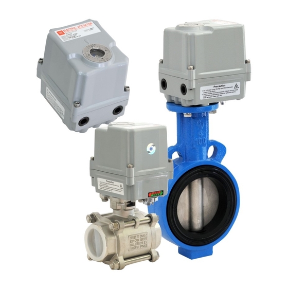
- Page 1 ELECTRIC ACTUATOR HQ006 INSTALLATION AND OPERATION MANUAL www.challengervalves.com.au QAD#IM6010 RevD 11.01.19...
- Page 2 CONTENTS COMPANY OVERVIEW INTRODUCTION PRODUCT IDENTIFICATION GENERAL INFORMATION AND FEATURES INSTALLATION INSTRUCTION OPERATION INSTRUCTIONS MAINTENANCE TROUBLE SHOOTING DIMENSIONS FOR ACTUATOR HEAD OFFICE 3 Glenn Street, Shepparton Victoria 3630 P: 03 5822 1533 F: 03 5822 2277 E: sales@challengervalves.com.au www.challengervalves.com.au QAD#IM6010 RevD 11.01.19...
- Page 3 QUALITY Challenger Valves provide in house testing and distributes a range of products that meet or exceed the highest Australian and International Standards, many of which carry the coveted Australian Standard Mark. Customer testaments are available on request.
-
Page 4: Product Identification
HQ 006 INTRODUCTION This installation and operating manual explains how to install, operate and maintain HQ-006 electric actuators. Safety notices in this manual detail precautions the user must take to reduce the risk of personal injury and damage to the equipment. -
Page 5: General Information And Features
F03, F05, AC110V, 220V, HQ006 12/14 0.4A/0.39A 0.02A/0.19A 0.4A DC24V, 24 VAC HQ006 Standard Technical Data (optional) Enclosure Rated Weatherproof IP67 Enclosure High grade aluminium alloy, corrosion coated Power Supply 110/220 VAC 1 Ph, 24 VAC - 24VDC 50/60Hz Motor... - Page 6 Manual Hand Wheel and Lever HQ actuators are provided with a manual operation system. The HQ006 actuator comes standard with a manual override nut. This is located on the bottom of the unit, and can be easily operated with a 5M wrench.
-
Page 7: Installation Instruction
Internal Parts for Standard Models Internal Parts - HQ006 Series 1. Motor 2. Indicator 3. Open Limit Switch 4. Additional Open Limit Switch 5. Close Limit Switch 6. Additional Close Limit Switch 7. Potentiometer Unit 8. Terminal 9. Heater 10. Capacitor... - Page 8 ACTUATOR MOUNTING DETAILS *Direct mounting / ISO (ISO standard) *Bracket Mounting HQ006: ISO5211 F03/F05 and F07 Star Adapter 14mm - 11 mm 11mm - 9mm Square Adapter 14mm - 11 mm 11mm - 9mm F03, F05, F07 Danger: HAZARDOUS VOLTAGE (Make sure all power is disconnected prior to mounting) Limit Switch Setting ...
- Page 9 Close Cam Setting Close Limit Switch Close limit Switch Cam (clockwise) 2mm Hexagon socket screw Key OPERATION INSTRUCTION Electrical Connections and Preliminary Test Loosen the screws on the actuator cover and lift it off Make sure that the power supply voltage is in accordance with the data on the actuator name plate ...
- Page 10 Wiring Diagrams for Standard Models - 240V AC HQ006 240V AC On/Off type Wiring Diagram Number HQ-110-A HQ006 240V AC PCU Type Wiring Diagram Number HQ-150-B QAD#IM6010 RevD 11.01.19...
- Page 11 Wiring Diagrams for Standard Models - 24V AC Wiring Diagram - 24V AC On/Off type Wiring Diagram Number HQ-740-B DC Wiring Diagram - 24V DC On/Off type Wiring Diagram Number HQ-840-B QAD#IM6010 RevD 11.01.19...
- Page 12 APPLICATION HKC - H K C CO. LTD NOTE: The HQ006 24V Unit requires the relay panel to be programmed ot suit either AC or DC operation. Use the below photos to set Dip Switches to suit. HQ 006-2 HQ 006-2...
-
Page 13: Maintenance
MAINTENANCE Caution: Turn off all power services before attempting to perform a service on the actuator. POTENTIAL HIGH PRESSURE VESSEL. Before removing or disassembling the actuator ensure the valve or other actuated devices are isolated and not under pressure. Maintenance under normal conditions at six month intervals, however when conditions are more severe, more frequent inspections may be advisable. -
Page 14: Troubleshooting
TROUBLE SHOOTING The following instructions are offered for the most common difficulties encountered during installation and start up. SYMPTOM PROBABLE CAUSE CORRECTIVE ACTION Motor not running Open in control unit Refer to appropriate wiring diagram and check for continuity Insulation resistance breakdown in motor Perform megger test No power available to actuator Tripped circuit breaker... - Page 15 DIMENSIONS FOR ACTUATOR HQ006 HQ006 On/Off Type Enclosure: IP67 Torque: 6Kg.m 125.5 Operation Time: 13sec Position Switch: 4 SPDT Switch Cable Entry: PG 13.5 x 2 Mounting Flange: F03, F05, F07 acc to DIN/ISO5211 Cable Entry: PG 13.5 Indicator M5 Bolt Hexagon Socket Head Cap Screws 126.4...
- Page 16 HQ006 PCU TYPE 103.6 Ø70/F7ISO 4-M8TAP DP12 Ø6.8 DRILL DP14 Ø50/F5ISO 4-M6TAP DP12 Handwheel Ø5 DRILL DP14 Ø36/F3ISO 8-M5TAP DP12 Ø4.2 DRILL DP14 Cable Entry: PG 13.5 126.4 212.4 QAD#IM6010 RevD 11.01.19...
- Page 17 HEAD OFFICE AND WAREHOUSE 3 Glenn Street Shepparton Victoria 3630 P: 1800 120 751 Email: sales@challengervalves.com.au www.challengervalves.com.au QAD#IM6010 RevD 11.01.19...
Need help?
Do you have a question about the HQ006 and is the answer not in the manual?
Questions and answers