Table of Contents
Advertisement
Quick Links
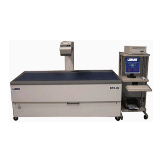
DPX-IQ
Operator's Manual
Software Version: 4.6
Documentation Version: 1/99C
Part Number: 5970
LUNAR Corporate Headquarters
313 West Beltline Highway
Madison, WI 53713 USA
+1 (800) 445-8627
+1 (608) 274-2663
+1 (608) 274-5374 (Fax)
LUNAR Europe N.V.
avenue R. Vandendriessche, 18/9
1150 Brussels
Belgium
+32-2-7770910
+32-2-7791039 (Fax)
LUNAR France
1, avenue d'Aix-en-Provence
13410 Lambesc
France
+33-4-42 57 17 97
+33-4-42 57 17 99 (Fax)
Internet Address: http://www.lunarcorp.com
™
LUNAR GmbH
Horbeller Strasse 33
D-50858 Köln
Germany
+49-2234-954590
+49-2234-273153 (Fax)
LUNAR Asia/Pacific
54 Taylor Street
West Pennant Hills, NSW 2125
Australia
+61-2-9873-1091
+61-2-9871-3758 (Fax)
Advertisement
Table of Contents

Subscribe to Our Youtube Channel
Summary of Contents for Lunar DPX-IQ
- Page 1 DPX-IQ ™ Operator’s Manual Software Version: 4.6 Documentation Version: 1/99C Part Number: 5970 LUNAR Corporate Headquarters 313 West Beltline Highway Madison, WI 53713 USA +1 (800) 445-8627 +1 (608) 274-2663 +1 (608) 274-5374 (Fax) LUNAR Europe N.V. LUNAR GmbH avenue R. Vandendriessche, 18/9...
- Page 2 LUNAR shall have no responsibility to replace the diskette(s) without additional cost to the customer. LUNAR will consider this warranty to be void if you fail to comply with the terms in the Software License Agreement or if the software is used on computer equipment not specified by LUNAR.
- Page 3 General Product Warranty LUNAR warrants that its products shall be free from defects in workmanship and materials and shall conform to published specifications for a period of one (1) year from the date of installation under normal use as prescribed in the Operator’s Manual for the product. This warranty does not apply to any products which have been subjected to neglect, accident or modification or any use other than specified as standard operating procedure in the manual.
- Page 4 • Perform the Quality Assurance procedure each morning. If any test fails, rerun the entire QA procedure. If a test fails again, contact the LUNAR Customer Support Department. Also, call LUNAR if more than two failures occur in a one-week period.
- Page 5 3078 Everburg Belgium Product Description: DPX Series Bone Densitometers (Includes DPX, DPX-MD, DPX-IQ DPX+, DPX-alpha, DPX-L) We hereby declare that the above described product conforms to the requirements of the European Council Directive 93/42/EEC, Medical Devices Directive, Annex II. This declaration is based on our Notified Body’s conformity assessment and certification of this site’s quality system in accordance with the requirements...
- Page 6 This page left blank intentionally. DPX-IQ Operator’s Manual...
-
Page 7: Table Of Contents
2.2 Start the DPX-IQ Program ........ - Page 8 Report Type ..........4-4 viii Table of Contents DPX-IQ Operator’s Manual...
- Page 9 C.4.1 Lateral Body ROIs ..........C-7 DPX-IQ Operator’s Manual...
- Page 10 G.3.2 Examine Reference Point ........G-8 Table of Contents DPX-IQ Operator’s Manual...
- Page 11 H.6.2 LUNAR 8022 X-ray Tube ........
- Page 12 Table of Contents DPX-IQ Operator’s Manual...
-
Page 13: Chapter 1:System Overview
Scan Table Assembly NOTE: DO NOT attempt servicing the scan table assembly. Please call the LUNAR Customer Support Department or your LUNAR distributor. Figure 1-1 shows the basic components of the scan table assembly: – scan table; — scan arm; ˜ control panel and ™ power switch. -
Page 14: Scan Table
• Status lights: The table below gives a description of the status lights. Light Status (on) Green (power) Power is supplied to the scan table. Amber (x-ray) X-ray tube assembly is supplying x-rays. Amber (shutter) Shutter is open. Yellow (laser) Laser is on. System Overview DPX-IQ Operator’s Manual... -
Page 15: System Safety
Adhere to the safety precautions in this section and obey the basic safety guidelines that follow at all times: • Do not attempt to service the DPX-IQ scanner. Please call LUNAR Customer Support or your LUNAR Distributor. • When the scan table is not in use, make sure the Shutter Open light is off. -
Page 16: Patient Safety
DO NOT STARE INTO THE LASER BEAM during image acquisition and Quality Assurance procedures. The label that follows is located on the scan arm and shows the location of the laser aperture. L a s e r A p e r t u r e System Overview DPX-IQ Operator’s Manual... -
Page 17: Radiation Safety
The leakage radiation from the x-ray tube assembly is low. Table 1-1 shows DPX-IQ scan modes and related kV and current settings. In addition, typical scan areas, irradiation times, and current time product are given. Only typical values are given for these parameters because the use of automatic scan (DPX-IQ SmartScan™) width values vary between patients to make sure minimum patient... -
Page 18: Symbols
Table1-1: Current, kV, and exposure information for DPX-IQ scan modes. (continued) Typical Scan Typical Typical Current Skin Current Sample Area Irradiation Time Product Entrance Scan Mode Size (mA) (mAs) Exposure (cm x cm) Times (sec) (µ µ µ µ Gy) Femur Hi-Res Fast 3.00... - Page 19 United States. LASER RADIATION DO NOT STARE INTO BEAM POWER OUTPUT: 1.00mW MAX. WAVELENGTH: 670nm CLASS II LASER PRODUCT This equipment complies with 21 CFR 1040.10 and 1040.11. DPX-IQ Operator’s Manual System Overview...
-
Page 20: Labels
X-ray Controller: This label shows x-ray controller LUNAR Corp. - Madison, WI USA compliance. It is located on the system computer if DPX Series / EXPERT X-Ray Controller LUNAR shipped a computer with the scanner. XRC1 MODEL: S/N: MANUFACTURED: LUNAR P/N:... -
Page 21: Emergency Stop Button And Failsafe Circuit
During a diagnostic failure, the Failsafe Circuit stops power to the scan motors and closes the x-ray shutter. A diagnostic failure number shows on the computer monitor: record the failure number and select !. Call the LUNAR Customer Support Department or your LUNAR distributor and give the failure number. -
Page 22: Facilities
1.2.9 Scattered Radiation Figures 1-4 and 1-5 show isodose diagrams for DPX-IQ scanners. Measurements at the surface of the scan table side panels were at background (<1 µGy/hr). The measurements were taken with a Victoreen 470A. The beam was attenuated through a 20.32 cm water phantom. - Page 23 35.6 cm 91.4 cm Front View Legend DPX-IQ scanner was run at 76 kV and 0.75 mA. DPX-IQ scanner was run at 76 kV and 4.75 mA. Figure 1-4. Isodose diagram of the 240-cm DPX-IQ scanner DPX-IQ Operator’s Manual System Overview 1-11...
- Page 24 35.6 cm 91.4 cm Front View Legend DPX-IQ scanner was run at 76 kV and 0.75 mA. DPX-IQ scanner was run at 76 kV and 4.75 mA. Figure 1-5. Isodose diagram of the 180-cm DPX-IQ scanner 1-12 System Overview DPX-IQ Operator’s Manual...
-
Page 25: System Maintenance
3. Push the emergency stop button again to reset the system. 4. Select"! to continue. The program resets the system. If the emergency stop procedure does not work, call the LUNAR Customer Support Department or your LUNAR distributor. DPX-IQ Operator’s Manual... -
Page 26: Preventive Maintenance
Complete system Quality Assurance procedures daily. Make sure each QA procedure passes. If your system does not pass a test, complete the Quality Assurance procedure again. If the procedure fails a second time, call the LUNAR Customer Support Department or your LUNAR distributor. 1.4.3... -
Page 27: Chapter 2:Basic Procedures
2.2 Start the DPX-IQ Program ........ -
Page 28: Common Keys
* Select Language to change the language shown on the screen and the printed reports. + Select Reference Population to access the reference databases necessary to compare BMD results. , Exit to leave the LUNAR program and go back to the Windows desktop. Figure 2-1. Options screen 2.1.2 Common Keys... -
Page 29: Start The Dpx-Iq Program
• Use the page up and page down keys to select specified options shown during the program. Start the DPX-IQ Program 1. Turn on the scanner for one hour. LUNAR recommends you leave the scanner on at all times. 2. Turn on the printer, computer, and monitor. -
Page 30: Basic Steps For Image Acquisition
NOTE: If you notice problems in the display image during acquisition, complete the scan and analyze the image. (Refer to section 2.4.) The problems should be corrected in the analysis. If not, perform another scan. If this happens repeatedly, contact LUNAR Customer Support. Basic Procedures DPX-IQ Operator’s Manual... -
Page 31: Add Patient Or Select Patient
2. Select the patient name. Select"!. The Mandatory Information screen is shown. 3. Move the cursor to the necessary field. 4. Record the new information. Select 0 to move the cursor to the next field. 5. Select ! to save changes. DPX-IQ Operator’s Manual Basic Procedures... -
Page 32: Stop A Scan Image Acquisition
Select the applicable scan type before you start a scan analysis: 1. At the Options screen, select (. 2. Use the arrow keys to highlight the necessary scan type. Select !. 3. The Options screen for the scan type is shown. Basic Procedures DPX-IQ Operator’s Manual... -
Page 33: Select Patient Scan File
1. Make sure Centering is highlighted on the screen. 2. Select 1. Use the arrow keys to move the center of the grid to the area of the scan image to be centered. DPX-IQ Operator’s Manual Basic Procedures... -
Page 34: Grey Scale
BMD is measured in grams per centimeter squared (g/cm • BMC (Bone Mineral Content)—The BMC value gives a measurement of bone mineral found in the region of interest. BMC is measured in grams (g). Basic Procedures DPX-IQ Operator’s Manual... -
Page 35: Print A Dicom Report (Optional)
2. Select #. The Patient Directory screen is shown. 3. Use the arrow keys to highlight the necessary patient scan files. 4. Select !. The Chronological Results screen shows a list of results for all of the patient's scans. DPX-IQ Operator’s Manual Basic Procedures... -
Page 36: Chronological Results Screen Options
To highlight a different scan press % and use the arrow keys. 6. Select ' to print the graph. Figure 2-2. Patient results graph 2-10 Basic Procedures DPX-IQ Operator’s Manual... -
Page 37: Archive Scan Files
• If yes, return to step 3. • If no, select / to go back to the Database Utilities screen. 7. Store the archive disk in a safe place to prevent damage or loss of scan data. DPX-IQ Operator’s Manual Basic Procedures 2-11... -
Page 38: Change Archive Destination And Directory
2. Move the cursor to the line that follows: Archive Drive.: a:\ar_data\ 3. Type over the line to record the name of the directory and/or drive destination. Follow the directory name with a backslash (\ ). 2-12 Basic Procedures DPX-IQ Operator’s Manual... -
Page 39: Chapter 3: Quality Assurance
Unsuccessful Quality Assurance Repeat procedure suggested Complete the QA tests again. If a test fails two times, call the LUNAR Customer Support Department or your LUNAR distributor. DO NOT try to scan a patient until a successful QA test is complete. - Page 40 • The Standard Values have CV values of 2.0% or less. Mean values do not change from the expected value by more than 5%. If these conditions are not successful, an error message shows on the bottom of the printout and on the screen. 7. Save the printout. Quality Assurance DPX-IQ Operator’s Manual...
-
Page 41: Collimation Ratio Test
If the system fails the Collimation Ratio test, you cannot access the forearm and small animal acquisition programs. A warning message shows when you try to enter either program. Call the LUNAR Customer Support Department if your system fails the collimation ratio test. -
Page 42: No Valid Qa Results Within The Past 2 Weeks
The phantom represents the typical density range and size of a normal human spine. The spine phantom (figure 3-3) consists of vertebrae L1 through L4. Parts of vertebrae T12 and L5 are landmarks used by the DPX-IQ program during analysis. LUNAR XXXX Figure 3-3. - Page 43 Test. NOTE: Refer to the QA printout before this scan if you think the values are not correct. Call LUNAR Customer Support or your Distributor. 8. Select / to go back to the AP Spine Acquisition screen. 9. To scan the encapsulated or water bath spine phantom: •...
- Page 44 13. Select !. The scan arm and detector move to the approximate start position and the program turns on the laser light. WARNING: Each Lunar scanner is equipped with a Class C A U T I O N LASER RADIATION DO NOT STARE INTO BEAM II Laser that is less than 1 milliwatt in strength.
-
Page 45: Analyze The Spine Phantom
10. Review the scan mode. You will find this mode on the Analysis Results report on the second line below the image. Verify that the scan mode is the same as the one used for previous scans. DPX-IQ Operator’s Manual Quality Assurance... -
Page 46: Monitor Precision Over Time
11. Record the BMD value of region L2-L4. This value must be within 3% of the average BMD value. If the average BMD values repeatedly vary by more than 3%, call the LUNAR Customer Support Department. 12. Save the analysis printouts. -
Page 47: Chapter 4: Default Settings
Default Settings Chapter 4 Contents Default settings are values the LUNAR program automatically uses. You can change some of the default settings to customize the program. Change default settings to relate to values you use most often. Chapter 4 includes the sections that follow: 4.1 Print Manager . -
Page 48: Set The Delayed Print Time
If you have more than one printer, you can connect each printer to its own port. An Applications Specialist does this during system installation. LUNAR software lets you use three printer ports. You can set the active port to LPT1 (Port1), LPT2 (Port2), or LPT3 (Port3). -
Page 49: General Default Settings
Bone Results, Verify Values, Profiles, Analysis Results screens, Results printouts, and Ancillary printouts. The default setting is “Last Name.” Other possible options are listed on the screen when you highlight Patient ID. DPX-IQ Operator’s Manual Default Settings... -
Page 50: Height/Weight Units
Mandatory Information screen. Measurement units are shown on the Results and Ancillary printouts. Date Format Date Format sets the display of dates thru the LUNAR program and on the Results and Ancillary printouts: • The dd.mm.yy format shows the date as day.month.year (16.01.91). -
Page 51: Show Selected Roi Only
% Young Adult value. Normals Graph Type Normals Graph Type selects one of two types of graphs: Lunar Standard and WHO Fracture Risk. Lunar Standard, the default setting, is shown in figure 4-1 below. - Page 52 Figure 4-1. Lunar Standard Graph Display for AP Spine WHO Fracture Risk is available for AP spine, Femur, and Total Body scan analysis. Fracture Risk replaces the standard analysis graph with one designed to assess fracture risk using World Health Organization categories. Refer to figure 4-2 below.
-
Page 53: Apply Weight Adjustments
3. Highlight Solid/Clear option. Select % for a solid blue bar. Select )&for a clear bar. 4. Highlight the standard deviation option. Record the necessary standard deviation value for the Age Regression Line. The default standard deviation for Bar 1 is 1.00. DPX-IQ Operator’s Manual Default Settings... - Page 54 4.6d ❶ ❷ ❸ Figure 4-3. Analysis Results report Default Settings DPX-IQ Operator’s Manual...
-
Page 55: Select Language
Options screen. Select Reference Population The LUNAR program lets you compare patient bone mineral density (BMD) to a database of reference information. You can choose from several national databases. Use of the reference population comparisons is fully at the discretion of the clinician. - Page 56 This page left blank intentionally. 4-10 Default Settings DPX-IQ Operator’s Manual...
-
Page 57: Appendix A:ap Spine Image Acquisition And Analysis
5. Help the patient lie on the scan table. Select !. The scan arm and detector move to the approximate start position and the program turns on the laser light. WARNING: Each Lunar scanner is equipped with a Class C A U T I O N... - Page 58 • The top of L5 (–) is in the scan image. • The scan shows 5–15 lines of the iliac crest (—). If the detector position is not correct, select # to stop the scan. Refer to section 2.3.5. AP Spine DPX-IQ Operator’s Manual...
-
Page 59: Ap Spine Analysis
2. At the Bone Results screen, make sure the space markers and labels are correct. Are changes necessary? • If yes, select $. The Spaces/Labels screen appears. Use the options shown on the screen to change space markers and label vertebrae. • If no, continue with step 5. DPX-IQ Operator’s Manual AP Spine... - Page 60 For AP spine analysis, you can choose to display a WHO Fracture Risk graph (shown on the right) instead of the Lunar Standard graph (shown on the left). Refer to section 4.2.3 for an explanation of the Fracture Risk graph and for more information about changing Printout Display Options in the General Default Settings.
- Page 61 Figure A-5. AP Spine Analysis Report Figure A-6. AP Spine Ancillary Report DPX-IQ Operator’s Manual AP Spine...
-
Page 62: Analysis Information
To position a space marker, use the arrow keys to select the marker and select $. Refer to the histogram and use the options shown on the screen to move the marker. Select ! to save changes. – — Figure A-7. Intervertebral Space Marker position AP Spine DPX-IQ Operator’s Manual... -
Page 63: Examine Baseline And Edge Markers
The high density points contained inside the area between the edge markers and above the baseline are used to calculate results. ™ Soft Tissue Points: The low points on the profile identify soft tissue the program does not use to calculate results. DPX-IQ Operator’s Manual AP Spine... -
Page 64: Examine Baselines
TIMES if it is necessary to change the baseline and edge markers. To change the baseline, select # to move the baseline up or $ to move the baseline down. Figure A-10. Correct baseline position AP Spine DPX-IQ Operator’s Manual... -
Page 65: Examine Edge Markers
To change an edge marker, use the keys % or ) to select an edge marker. Use the arrow keys to position the edge marker. Figure A-12. Correct Edge marker position DPX-IQ Operator’s Manual AP Spine... -
Page 66: Complete A Body Roi Analysis
• If no, continue with step 5. – — — – Figure A-13. Body ROIs 5. Select !. The Bone Results screen is shown. 6. Highlight the region to be shown on the Analysis Results screen. A-10 AP Spine DPX-IQ Operator’s Manual... - Page 67 7. Select !. The Analysis Results screen is shown. 8. Select # to save changes. 9. Select $ and record the number of Analysis Results and/or Ancillary reports necessary. Select ! to print the reports. DPX-IQ Operator’s Manual AP Spine A-11...
- Page 68 This page left blank intentionally. A-12 AP Spine DPX-IQ Operator’s Manual...
-
Page 69: Appendix B:femur Acquisition And Analysis
If you use this material, make sure there is at least 15 cm of soft tissue and tissue-equivalent material in the entire scan region for a 750 µ A scan and a combined total of 18.75 cm for a 3000 µ A scan. DPX-IQ Operator’s Manual Femur... - Page 70 ˜ Figure B-1. Patient position 8. The DPX-IQ unit includes one of the two foot braces shown in figures B-2 and B-3. Follow the instructions for your model’s brace. (If your unit has both foot braces, use the brace shown in figure B-3.) •...
- Page 71 10. Select !. The scan arm and detector move to the approximate starting position and the program turns on the laser light. WARNING: Each Lunar scanner is equipped with a Class C A U T I O N LASER RADIATION DO NOT STARE INTO BEAM II Laser that is less than 1 milliwatt in strength.
- Page 72 14. Select ! to go back to the Femur Options screen. Figure B-5. Femur scan image 15. After the scan, remove the patient’s feet from the foot brace and help the patient off the scan table. Femur DPX-IQ Operator’s Manual...
-
Page 73: Acquisition Information
B.2.1 Position Rice Bags A common tissue-equivalent material is white, uncooked rice. LUNAR recommends you use 10 cm of rice to equal 8 cm of soft tissue. The minimum tissue equivalent thickness must be 15 cm for 750µA scans and 18.75 cm for 3000µA scans. Figure B- 5 shows the correct position of rice bags: –... -
Page 74: Dualfemur™ Acquisition
B.2.3 DualFemur™ Acquisition NOTE: DualFemur acquisition is not available for the Compact DPX-IQ. In software versions earlier than 4.6d, DualFemur acquisition begins with the right femur. During a DualFemur™ acquisition, the program acquires the left femur first: you must position the laser light for the left femur before you start a DualFemur™... - Page 75 WHO Fracture Risk graph (shown on the right) instead of the Lunar Standard graph (shown on the left). Refer to section 4.2.3 for an explanation of the Fracture Risk graph and for more information about changing Printout Display Options in the General Default Settings.
- Page 76 Figure B-8. Femur Analysis Report Figure B-9. Femur Ancillary Report Femur DPX-IQ Operator’s Manual...
-
Page 77: Analysis Information
Refer to the information that follows to make sure the position of the Neck ROI is correct (figure B-11): – soft tissue should be contained in all four corners of the ROI. — the ROI is perpendicular to the femoral neck. DPX-IQ Operator’s Manual Femur... -
Page 78: Position The Neck Roi
– perpendicular to the axis of the femoral neck, and — near the proximal (top) end of the femoral neck. 3. Select + then !. The program finds the area that contains the lowest bone density and positions the other three ROIs. B-10 Femur DPX-IQ Operator’s Manual... - Page 79 – — Figure B-12. Position Neck ROI DPX-IQ Operator’s Manual Femur B-11...
- Page 80 This page left blank intentionally. B-12 Femur DPX-IQ Operator’s Manual...
-
Page 81: Appendix C:lateral Spine Image Acquisition And Analysis
• make sure the patient’s spine is parallel to the scan table (˜): position the support wedge below the waist until the patient’s hips and shoulders create a straight line parallel to the scan table. DPX-IQ Operator’s Manual Lateral Spine... - Page 82 • Make sure the patient's arms are not inside the scan path. – ˜ — Figure C-2. Patient position 8. Select !. The scan arm and detector move to the approximate start position and the program turns on the laser light. Lateral Spine DPX-IQ Operator’s Manual...
- Page 83 WARNING: Each Lunar scanner is equipped with a Class C A U T I O N LASER RADIATION DO NOT STARE INTO BEAM II Laser that is less than 1 milliwatt in strength. POWER OUTPUT: 1.00 mW MAX WAVELENGTH: 670 nm CLASS II LASER PRODUCT DO NOT STARE INTO THE BEAM.
-
Page 84: Install The Lateral Positioner
2. At the Bone Results screen, make sure the labels, space markers, and body ROIs are correct. Are changes necessary? • If yes, select $. The Auto Analysis screen is shown. Continue with step 3. • If no, continue with step 6. Lateral Spine DPX-IQ Operator’s Manual... - Page 85 8. Select # to save changes. 9. Select $ and record the necessary number of Analysis Results and/or Ancillary reports (figures C-6 and C-7). Select ! to print the reports. Figure C-5. Analysis Results screen DPX-IQ Operator’s Manual Lateral Spine...
- Page 86 Figure C-6. Lateral Spine Analysis Report Figure C-7. Lateral Spine Ancillary Report Lateral Spine DPX-IQ Operator’s Manual...
-
Page 87: Analysis Information
2. Use the arrow keys to select the labels. As a reference (figure C-9), use the illiac crest (–) at the bottom of the scan image as a landmark: the vertebra immediately above the illiac crest is L4 (—). DPX-IQ Operator’s Manual Lateral Spine... -
Page 88: Examine Space Markers
If a space marker is not correct, use the arrow keys to select the marker and select $. Refer to the histogram and use the options shown on the screen to move the marker. Select"! to save changes. – — Figure C-10. Space markers Lateral Spine DPX-IQ Operator’s Manual... -
Page 89: Examine Edge Markers And Lateral Body Rois
If it is necessary to change a profile, select %&or ) and use the arrow keys to move the profile. Make sure you select + to examine the placement of body ROIs. – Figure C-11. Profiles DPX-IQ Operator’s Manual Lateral Spine... -
Page 90: Examine Lateral Body Rois
If it is necessary to position an ROI, select the Move (#), Expand ($), or Rotate (%) options and use the arrow keys to position the ROI. — – — Figure C-12. Correct ROI position C-10 Lateral Spine DPX-IQ Operator’s Manual... -
Page 91: Total Body Image Acquisition
*Use the screening mode for fast image acquisition if you do not have time to use another mode. 3. Examine the other scan values and select / to go back to the Total Body Acquisition screen. DPX-IQ Operator’s Manual Total Body... - Page 92 NOTE: An autostop feature automatically stops the scan after the detector passes the patient’s feet. 8. Remove the patient’s feet and legs from the straps. Help the patient off the scan table. 9. Select ! to go back to the Total Body Options screen. D-2 Total Body DPX-IQ Operator’s Manual...
-
Page 93: Total Body Image Analysis
For Total Body analysis, you can choose to display a WHO Fracture Risk graph (shown on the right) instead of the Lunar Standard graph (shown on the left) when you are doing a Total analysis. Refer to section 4.2.3 for an explanation of the Fracture Risk graph and for more information... - Page 94 8. Select $ and record the necessary number of Analysis Results and/or Ancillary reports (figures D-4, D-5, and D-6). Select ! to print the reports. Figure D-3. Analysis Results screen Figure D-4. Total Body Analysis Report (page 1) D-4 Total Body DPX-IQ Operator’s Manual...
- Page 95 Figure D-5. Total Body Analysis Report (page 2) 3.6y Figure D-6. Total Body Ancillary Report DPX-IQ Operator’s Manual Total Body...
-
Page 96: Tissue Quantitation
• Fat as a percentage of body mass (soft tissue and bone mass) for each region. • Total soft tissue content in grams (fat and lean tissue combined). • Fat tissue content in grams. D-6 Total Body DPX-IQ Operator’s Manual... -
Page 97: Analysis Information
œ Lumbar—Position the lumbar cut to contain the last vertebra above the pelvis. Make sure the spine is not included in the pelvis cut region. Dorsal—Position the dorsal cut immediately below T12 (to identify T12, locate the ribs that extend from it). DPX-IQ Operator’s Manual Total Body... -
Page 98: Standard And Extended Research Analysis
1. At the Bone Results screen, select $. The Auto Analysis screen is shown. 2. The mode NOT in use is shown next to option $. Select $ to change the analysis mode. 3. Select !. The message that follows is shown: Change Cuts Now? (Y/N) D-8 Total Body DPX-IQ Operator’s Manual... - Page 99 When finished, select !. The program processes information from the new cut positions and the Bone Results screen is shown. 5. Select !. The Bone Results screen is shown. Select # to save changes. DPX-IQ Operator’s Manual Total Body...
- Page 100 This page left blank intentionally. D-10 Total Body DPX-IQ Operator’s Manual...
-
Page 101: Forearm Image Acquisition
3. Record or examine the following information: • Forearm Length—the length of the forearm to be scanned. • Patient Side—the arm to be scanned, left or right. (LUNAR recommends the patient’s non-dominant arm.) • Scan Mode—150µA is the only scan mode available. Select ! when the Scan Mode window is shown. - Page 102 9. Select !. The scan arm and detector move to the approximate start position and the program turns on the laser light. WARNING: Each Lunar scanner is equipped with a Class C A U T I O N LASER RADIATION DO NOT STARE INTO BEAM II Laser that is less than 1 milliwatt in strength.
-
Page 103: Measure The Forearm Length
E.2.1 Measure the Forearm Length Measure the forearm (figure E-4 from the ulna styloid process (–), the protrusion on the wrist) to the elbow (—). – — Figure E-4. Measure the forearm DPX-IQ Operator’s Manual Forearm... -
Page 104: Record The Scan Length
To select the scan length, refer to the four scan sites that follow (figure E-5): • Total—scans the entire forearm shaft from the wrist to the 33% shaft site (–). LUNAR recommends that you use the Total scan length. • Shaft—scans the 33% shaft site (–). -
Page 105: Forearm Position
3. Make sure the Bone and ROI labels are correct. Are changes necessary? • If yes, select *. The Labels screen is shown. Use the options shown on the screen to change bone and ROI labels. • If no, continue with step 4. DPX-IQ Operator’s Manual Forearm... - Page 106 9. Select !. The Analysis Results screen is shown (figure E-8). 10. Select # to save changes. 11. Select $ and record the necessary number of Analysis Results and/or Ancillary reports (figures E-9 and E-10). Select ! to print the reports. Figure E-8. Analysis Results screen Forearm DPX-IQ Operator’s Manual...
- Page 107 Figure E-9. Forearm Analysis Report Figure E-10. Forearm Ancillary Report DPX-IQ Operator’s Manual Forearm...
-
Page 108: Analysis Information
Please refer to section A.3.2 for more information on the line profile. NOTE: The Line Profile is an optional feature for forearm analysis. Refer to chapter 4 to activate the “Display Line Profile” option. Figure E-11. Scan image and profile Forearm DPX-IQ Operator’s Manual... -
Page 109: Examine Baselines
˜ The third edge marker is positioned on the first bone point after the soft tissue points between the two bones. ™ The fourth edge marker is positioned on the last bone point before the soft tissue points start. ˜ – — ™ Figure E-12. Edge marker position DPX-IQ Operator’s Manual Forearm... -
Page 110: Examine Roi Position
ROI, move the Ultradistal ROI down until the endplate is not included (figure E-14). 33% ROI The recommended height of the 33% ROI is 20 mm and is centered at 33.33% of the total arm length as measured at the ulna styloid process (figure E-14). E-10 Forearm DPX-IQ Operator’s Manual... -
Page 111: 5Mm Roi
The recommended height of the 10% ROI is 15 mm. The ROI is centered at 10% of the total arm length as measured at the ulna styloid process (figure E-15). Figure E-15. Correct position of 5 mm and 10% ROI DPX-IQ Operator’s Manual Forearm E-11... -
Page 112: Total Roi
Total ROI The Total ROI contains the 33% ROI (– in figure E-16), the Ultradistal ROI (—), and the area between them (˜). — ˜ – Figure E-16. Total ROI E-12 Forearm DPX-IQ Operator’s Manual... -
Page 113: Hand Image Acquisition
NOTE: Use the same scan width and scan length values for future scans of the patient. 3. Select / to go back to the Hand Acquisition screen. 4. Select !. The scan arm and detector move to the HOME position. 5. Remove the pad from the scan table. DPX-IQ Operator’s Manual Hand... - Page 114 7. Select !. The scan arm and detector move to the approximate start position and the program turns on the laser light. WARNING: Each Lunar scanner is equipped with a Class C A U T I O N LASER RADIATION DO NOT STARE INTO BEAM II Laser that is less than 1 milliwatt in strength.
-
Page 115: Hand Image Analysis
4. Select # to save the analysis results. 5. Select $ and record the number of Analysis Results and/or Ancillary reports necessary (figures F-5 and F-6). Select ! to print the reports. Figure F-4. Analysis Results screen DPX-IQ Operator’s Manual Hand... - Page 116 Total Bone Calcium (g).. 21.99 Air Points....3482 Tissue Points... 5893 Bone Points..... 1808 Total Points.... 9375 R-Value Points..1422 **Ancillary results for research purposes only, not clinical use. ® #0001 Figure F-6. Hand Ancillary Report Hand DPX-IQ Operator’s Manual...
-
Page 117: Orthopedic Hip Image Acquisition
Select !. • Scan Width—Use the default value of 150 if you do not have a specified scan width. • Scan Length—Use the default value of 100 if you do not have a specified scan length. DPX-IQ Operator’s Manual Orthopedic Hip... - Page 118 DO NOT perform the scan if the patient is uncomfortable. • Move the foot brace and the patient’s leg until the femur of the leg to be scanned is parallel to the center line on the scan pad. G-2 Orthopedic Hip DPX-IQ Operator’s Manual...
- Page 119 Refer to section B.2.1 for more information. If the position of the detector is not correct, select # to stop the scan. Follow the screen prompts to position the detector again and start the scan. DPX-IQ Operator’s Manual Orthopedic Hip...
-
Page 120: Orthopedic Hip Image Analysis
4. Select +. The Auto Analysis screen is shown. Make sure the ROIs and the Reference Point positions are correct. 5. Select !. The Bone Results screen is shown (figure G-4). 6. Select ) to save changes. G-4 Orthopedic Hip DPX-IQ Operator’s Manual... - Page 121 7. Select * and record the necessary number of Analysis Results and/or Ancillary reports (figures G-5 and G-6). Select ! to print the reports. Figure G-4. Bone Results screen Figure G-5. Orthopedic Hip Analysis Report DPX-IQ Operator’s Manual Orthopedic Hip...
-
Page 122: Analysis Information
The Line Profile uses edge markers to separate bone from the hip implant for analysis results. NOTE: The line profile is an optional feature for orthopedic hip analysis. See chapter 4 to activate the “Display Line Profile” option. G-6 Orthopedic Hip DPX-IQ Operator’s Manual... -
Page 123: The Line Profile
• Right Femur Edge—The right femur edge marker (›) is on the point immediately after the bone points join the soft tissue points. NOTE: Change edge markers only if they are obviously not correct. Let the program calculate the edges for you. DPX-IQ Operator’s Manual Orthopedic Hip... -
Page 124: Examine Reference Point
In addition, the vertical line of the Reference Point touches the curve of the lesser trochanter. NOTE: Only Standard Analysis uses a Reference Point. Figure G-9. Reference Point G-8 Orthopedic Hip DPX-IQ Operator’s Manual... -
Page 125: Examine Standard Analysis Rois
• ROI A is directly above ROI B. The bottom edge of ROI A touches the top edge of ROI B. Figure G-10. Standard Analysis ROIs DPX-IQ Operator’s Manual Orthopedic Hip... -
Page 126: Examine Gruen Analysis Rois
(if applicable), implant length, and scan width settings. NOTE: The height of ROIs 1, 2, 6, and 7 is one-third the length of the implant if a modified Gruen analysis is not being completed. Figure G-11. Standard Gruen ROIs G-10 Orthopedic Hip DPX-IQ Operator’s Manual... -
Page 127: Modified Gruen Analysis
2a–2c and 6a–6c in the middle third of the implant, and ROIs 3a–3c and 5a–5c in the bottom third of the implant. ROI 4 is below the distal tip of the implant (figure G-13). DPX-IQ Operator’s Manual Orthopedic Hip G-11... -
Page 128: Offset, Perimeter, And Rim Options
2. Record the width (0–10mm) necessary for the bone region. 3. Select 0. The program shows a set of edge markers the distance you specified from the Offset edge markers. G-12 Orthopedic Hip DPX-IQ Operator’s Manual... -
Page 129: Set A Rim Value
Longitudinal Histogram. However, the bone region on the Transverse Histogram screen cannot be more than 12 mm tall. In addition, the program does not calculate BMD values for the regions shown on the histogram. DPX-IQ Operator’s Manual Orthopedic Hip G-13... - Page 130 Figure G-15. Transverse Histogram screen G-14 Orthopedic Hip DPX-IQ Operator’s Manual...
-
Page 131: Appendix H:specifications
Room dimensions must be at least 12' x 12' (3.7 m x 3.7 m) for a 240-cm long DPX-IQ system, and 9' x 9' (2.7 m x 2.7 m) for a 180-cm long DPX-IQ system. Because of cable lengths, all DPX-IQ components must be in the same room. For radiation and electrical safety, the console table must be at least 3 feet from the scan table. -
Page 132: Component Specifications
All systems purchased in the United States include a computer and monitor: • Computer—Refer to section H.7 for compatible computer components and minimum system requirements. • Monitor—A 17” (43.2 cm) monitor is standard for DPX-IQ systems. NOTE: Refer to your product literature for component specifications. H.2.1 Printer Your system may include one of the printers that follow. -
Page 133: Scan Table
• DPX-IQ240 (full table) 8.1"(L) x 24.6"(W)* x 52.2"(H)** (197.5 cm x 62.3 cm x 132.5 cm) • DPX-IQ 180 (compact table) 2.6"(L) x 21.3"(W)* x 52.2"(H)** (133 cm x 54.0 cm x 132.5 cm) *Width is measured from the front edge of the scan table to the back edge of the scan arm. -
Page 134: Programs
• Dust, Fumes and Debris: Install the system in a clean, ventilated area. Dust and other airborne debris can cause the diskette drive heads and other sensitive mechanical components to malfunction. LUNAR recommends that you do not smoke in the scanner room. -
Page 135: Power Specifications
115 Range: 103-127 VAC 50/60 Hz 10A 230/240 Range: 207-264 VAC 50/60 Hz 7.5A H.6 X-ray Generator Specifications H.6.1 X-ray Generator Table H-1 contains information about the X-ray generator for DPX-IQ series devices. Table H-1: X-ray generator technical information. Classification Class I Equipment IEC 601-2-7 5.1... - Page 136 Spellman X2112/X2113/ rev. K and higher. IEC 601-2-7 6.8.1 Allowable high voltage supplies Bertran 2411P and 2411N rev. A and and 50.2.101-102 higher. LUNAR p/n 0311 and 0312. IEC 601-2-7 6.8.1 Allowable tube head assemblies LUNAR model 2288 or equivalent and 50.2.101-102...
-
Page 137: Lunar 8022 X-Ray Tube
Figure H-1. Reference axis and target angles for tube head assembly H.6.2 LUNAR 8022 X-ray Tube Table H-2 gives LUNAR 8022 X-ray tube information. Table H-2: LUNAR 8022 X-ray tube technical information. 361 Watts for an equivalent Nominal anode input power... -
Page 138: Lunar 2288 X-Ray Tube Head Assembly
H.6.3 LUNAR 2288 X-ray Tube Head Assembly Beam filtration is permanently fixed at 3.2 mm Aluminum-equivalent. Refer to table H-3 for 2288 X-ray tube head assembly technical information. Table H-3: LUNAR 2288 X-ray tube assembly technical information. Quality equivalent filtration 41 mm AL/76 kV... -
Page 139: Laser Specifications
Figure H-4. Cathode emission characteristics Figure H-5. X-ray tube assembly heating/cooling curves H.6.4 Laser Specifications Table H-4 gives the specifications for the LUNAR laser. Table H-4: Laser specifications. Output Power <1mW Wavelength 670nm Frequency Drift 0.25nm/C Laser Structure Gain Guided... -
Page 140: Compatible Components
• 8X CD ROM • 1 MB Video RAM • 14” SVGA Monitor Table H-5 gives components certified to the FDA for use with DPX-IQ scanners and is updated periodically. Contact LUNAR for a current listing of compatible components. H-10 Specifications... - Page 141 —2GB-16MB w/Windows '95 4769 P166GsM: 2GB-32MB-166MHZ 4838 P5MMX200/GXiM: 2GB-32MB 5473 P5MMX166/GsM: 2GB, 32MB 5475 P6266/GXA: 3.2GB, 32MB, 233MHz w/Windows ‘95 5579 Controller–DPX-IQ ACER America Computer Models 2021: 2GB-16MB-166MHz 4761 2181: 6.4GB-32MB-233MHz 5524 2341: —8MB RAM 4115 —16 MB RAM 4013 —1.6GB-32MB-133MHz (black)
- Page 142 Bertan Models: —2411AP 0312 —2411AN 0311 Tube Head Assembly LUNAR X-Ray Tube Head Assembly 2288 Dell Computer Corporation, Austin, TX ACER America Corporation, San Jose, CA CITUS (Granite Microsystems), Mequon, WI Iomega Corporation, Roy, Utah Spellman High Voltage Electronics Corporation Hauppauge, NY...
-
Page 143: Appendix I: Comparison To Reference Population
Appendix I:Comparison to Reference Population Reference Data The reference data for the LUNAR DPX were based on ambulatory subjects from the general population who were free from chronic diseases affecting bone and who were not taking medications which influence bone (such as corticosteroids, anticonvulsants and thyroxine). -
Page 144: Reference Population Database
US, England, and Northern Europe. The variation of mean BMD values among geographical sites contributing normal data was about 1.3% (SD/mean). All data from these studies were acquired with LUNAR DPX instrumentation. Table I-1 lists the number of subjects in the reference population for each measurement site. - Page 145 (0.13) 20–29 1.098 1.038 0.950 1.105 30–39 1.045 0.937 0.908 1.071 40–49 0.984 0.853 0.892 1.042 50–59 0.956 0.803 0.902 1.029 60–69 0.909 0.744 0.873 1.000 70–79 0.876 0.706 0.845 0.961 Total 1734 DPX-IQ Operator’s Manual Comparison to Reference Population...
- Page 146 NHANES Values converted to DPX-equivalent BMD Table I-6 lists the mean BMD used in LUNAR’s total body reference data for females. Table I-7 lists the mean BMD used in LUNAR’s total body reference data for males.
- Page 147 Table I-8: Male and female BMD for radius shaft (SD=0.07 g/cm Female Male 20–29 0.700 0.790 30–39 0.710 0.820 40–49 0.700 0.820 50–59 0.660 0.780 60–69 0.580 0.770 70–79 0.530 0.740 80–89 0.490 0.730 Total 1685 DPX-IQ Operator’s Manual Comparison to Reference Population...
- Page 148 Table I-10: Male and female BMD for radius shaft (SD=0.07 g/cm Female Male 20–29 0.700 0.790 30–39 0.710 0.820 40–49 0.700 0.820 50–59 0.660 0.780 60–69 0.580 0.770 70–79 0.530 0.740 80–89 0.490 0.730 Total 1685 Comparison to Reference Population DPX-IQ Operator’s Manual...
-
Page 149: Age Adjustment
Troch = 1.010-(0.0053 X Age) 0.24 0.117 Troch = 0.838-(0.0023 X Age) 0.08 0.126 20–45 Total Body= 1.13+(0.0005 X Age) 0.00 0.088 45–65 Total Body= 1.40-(0.0053 X Age) 0.33 0.084 Total Body= 1.06-(0.0003 X Age) 0.00 0.073 DPX-IQ Operator’s Manual Comparison to Reference Population... -
Page 150: Weight Adjustment
Male Female Site (years) (years) Femur 20–45 20–45 AP Spine 20–45 20–45 Forearm 20–50 20–50 Lateral Spine 20–40 20–40 Total Body* 20–55 20–45 * For total body region only. Comparison to Reference Population DPX-IQ Operator’s Manual... -
Page 151: References
Caucasian, Asian, and Afro-Caribbean women. Clin Sci 87:587-591. 13. Looker AC, Wahner HW, Dunn WL, Calvo MS, Harris TB, Heyse SP, Johnston CC Jr, Lindsay RL, (1995) Proximal femur bone mineral levels of US adults. Osteoporosis Int 5:389-409. DPX-IQ Operator’s Manual Comparison to Reference Population... - Page 152 27. Pouilles JM, Tremollieres F, Ribot C (1995) Effect of menopause on femoral and vertebra bone loss. J Bone Miner Res 10:1531-1536. 28. Hui SL, Slemenda CW, Johnston CC Jr (1990) The contribution of bone loss to postmenopausal osteoporosis. Osteoporosis Int 1:30-34. I-10 Comparison to Reference Population DPX-IQ Operator’s Manual...
- Page 153 42. Lu PW, Briody JN, Ogle GD, Morley K, Humphries IRJ, Allen J, Howman-Giles R, Sillence D, Cowell CT (1994) Bone mineral density of total body, spine, and femoral neck in children and young adults: a cross-sectional and longitudinal study. J Bone Miner Res 9:1451-1458. DPX-IQ Operator’s Manual Comparison to Reference Population I-11...
- Page 154 Eur J Clin Nutr 22:454-460. 49. Wetzel R, Pfandl S, Bodenburg R, Puhl W (1996) Bone mineral density – reference values of healthy German females – examinations of the lumbar spine using LUNAR DPX. Osteologie 5:71-81.
-
Page 155: Appendix J: Precision And Accuracy
1 subject over 1 month. The precision error was about .015 g/cm for the neck region, or about 1.5% at a typical density of 1 g/cm . These precision results were summarized by Mazess et al (1989). DPX-IQ Operator’s Manual Precision and Accuracy... - Page 156 0.499 .006 0.499 .011 0.839 .013 Legs 0.801 .005 0.672 .009 1.281 .010 Trunk 0.587 .004 0.619 .008 0.940 .010 Spine 0.497 .007 0.575 .010 1.034 .020 Total 0.772 .003 0.731 .007 1.168 .007 Precision and Accuracy DPX-IQ Operator’s Manual...
-
Page 157: Accuracy
Accuracy The LUNAR DPX-IQ accurately measures BMC and BMD (figures J-1 and J-2). The BMC and BMD of three standard annuli containing bone equivalent material (made by Radiation Measurements of Middleton, Wisconsin) were calibrated at the University of Wisconsin Bone Mineral Laboratory against the ash-weight of known bone sections. - Page 158 The accuracy of the DPX total body scans was not directly evaluated on skeletons. Comparisons were made with conventional Gd DPA scans (LUNAR DP4 scanner) in 11 young subjects. The correlation between results was high (r=0.96, SEE=0.02 g/ ). The regression line was congruent with the identity line (figure J-3).
-
Page 159: References
4. Mazess RB, Peppler WW, Chesnut CH, Nelp WB, Cohn SH (1981) Total body bone mineral and lean body mass by dual-photon absorptiometry. II. Comparison with total body calcium by neutron activation analysis. Calcified Tissue International 33:361-363. DPX-IQ Operator’s Manual J-5 Precision and Accuracy... - Page 160 This page left blank intentionally. Precision and Accuracy DPX-IQ Operator’s Manual...
- Page 161 Display line profile, 4-4 Chronological results, 2-10 Clothing restrictions, 2-3 Femur, B-6 Computer Forearm, E-5 ACER, H-11 Hand, F-3 CITUS, H-11 Lateral Spine, C-4 Common keys, 2-2 Orthopedic Hip, G-4 Controllers, H-11 Results, 2-8 Dell, H-11 Scan image, 2-8 DPX-IQ Operator’s Manual Index...
- Page 162 DPX-IQ interface, 2-1 5mm ROI, E-11 Minimum requirements, H-10 Acquisition, E-1 Control panel, 1-2 Analysis, E-5 Baseline, E-9 Bone labels, E-8 Edge markers, E-9 DICOM report, 2-9 Forearm length, E-3 Directory Positioner, E-4 Change archive destination, 2-12 Region lables, E-8...
- Page 163 Report defaults, 4-3 Normals Graph Color Bars, 4-5 Select printer and active port, 4-2 Normals Graph Type, 4-5 Fracture Risk, 4-5, 4-6 Lunar Standard, 4-5, 4-6 QA (see Quality Assurance), 3-1 Quality Assurance Monitor precision, 3-8 Optional information Perform, 3-1...
- Page 164 Standard analysis, D-8 Emergency stop button, 1-9 Tissue Quantitation, D-6 Laser, 1-4 Type, 2-7 Operator, 1-3 Patient, 1-4 Pregnancy restrictions, 2-3 Radiation, 1-5 Weight adjustment, I-8 Symbols, 1-6 System, 1-3 Scaling factor, 2-7 Scan image Adjust, 2-7 Index DPX-IQ Operator’s Manual...
- Page 165 X-ray generator, H-5 X-ray tube Lunar 2288, H-7, H-8 Lunar 8022, H-7 Young Adult Results defined, 2-9 Young adult BMD comparison, I-8 Display on printout, 4-5 DPX-IQ Operator’s Manual Index...
- Page 166 This page left blank intentionally.
Need help?
Do you have a question about the DPX-IQ and is the answer not in the manual?
Questions and answers