Sign In
Upload
Download
Table of Contents
Contents
Add to my manuals
Delete from my manuals
Share
URL of this page:
HTML Link:
Bookmark this page
Add
Manual will be automatically added to "My Manuals"
Print this page
×
Bookmark added
×
Added to my manuals
Manuals
Brands
Marconi Instruments Manuals
Inverter
TF 995A/5
Operating and maintenance handbook
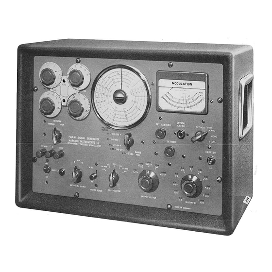
Marconi Instruments TF 995A/5 Operating And Maintenance Handbook
Fm/am signal generator
Hide thumbs
1
2
Table Of Contents
3
4
5
6
7
8
9
10
11
12
13
14
15
16
17
18
19
20
21
22
23
24
25
26
27
28
29
30
31
32
33
34
35
36
37
38
39
40
41
42
43
44
45
46
47
48
49
50
51
52
53
54
55
56
57
58
59
60
61
62
page
of
62
Go
/
62
Contents
Table of Contents
Bookmarks
Table of Contents
Table of Contents
Data Summary
Schedule of Parts Supplied
Introduction
2 Operation
Installation
Switching on and Warming up
Output Connectjons
Tuning
General Tuning
Use of the Crystal Calibrator
Incremental Frequency Controls
Interpolating Dial
Setting up for C.w. or Modulated Output
Continuous Wave
Amplitude Modulation
Frequency Modulation
Simultaneous F.M. and a
Output Arrangements
Outputs from L Fj.V to 100 MV at 52 and 75 Ohms
Outputs from 2 Fj.V to 200 MV at 75 Ohms Only
Outputs from 0·1 Fj.V to 10 MV at 52 and 75 Ohms
Output in Terms of Voltage Developed Across Externalload
Matching to Externalloads Other than 52 or 75 Ohms
Matching to Balanced Loads
Synchronizing Signal
3 Operational Summary
4 Technical Description
Circuits
Modulation Systems
Monitoring Arrangements
Power Unit
Maintenance
General
Removal of Case
Mains Input Arrangements
Access to Enclosed Sub-Assemblies
Unit
MULTIPLY by Attenuator
OUTPUT VOLTAGE Attenuator and Monitor Diode
Mains Input Filter Unit
Power Unit
Working Voltages
Replacement of Valves and Semiconductors
Preset and Speciall y Selected Components
Schedule of Tests
Apparatus Required
Insulation
Hum Level
Crystal Oscillator
Bask Oscillator
Frequency Multipliers
1,5- to L3-5-MC/S Band
Output Voltage Accuracy
Modulation Oscillator
Reactance Valve Input Potentiometer
Frequency Modulation
Incremental Frequency
High Deviation
Externai F.M.-Metering Accuracy
Internai a
Externai a
Spurious F.M. on C.W
And R.f. Units (Top View)
Unit General Underside View
Unit (Close-Up of Portion of Underside)
Unit Underside View
SPARES ORDERING SCHEDULE SOS L
Circuit Diagrams
Advertisement
Quick Links
1
Circuits
2
Circuit Diagrams
Download this manual
Table of
Contents
Previous
Page
Next
Page
1
2
3
4
5
Advertisement
Table of Contents
Need help?
Do you have a question about the TF 995A/5 and is the answer not in the manual?
Ask a question
Questions and answers
Related Manuals for Marconi Instruments TF 995A/5
Inverter Marconi Instruments TF 1066B/6 Operating Instructions Manual
Signal generator (47 pages)
Inverter Marconi Instruments 2040 Operating Manual
Signal generators (136 pages)
Related Products for Marconi Instruments TF 995A/5
Marconi Instruments TF 1066B/6
Marconi Instruments TF 1066B/6R
Marconi Instruments tf2603
Marconi Instruments TF 2700
Marconi Instruments TF 2502
Marconi Instruments TF 2337A
Marconi Instruments TF 2005R
Marconi Instruments TF 1247
Marconi Instruments TF 2170B
Marconi Instruments TF 2702
Marconi Instruments TF 2500
Marconi Instruments TF 1246
Marconi Instruments 2040
Marconi Instruments 2041
Marconi Instruments 2042
Table of Contents
Print
Rename the bookmark
Delete bookmark?
Delete from my manuals?
Login
Sign In
OR
Sign in with Facebook
Sign in with Google
Upload manual
Upload from disk
Upload from URL


Need help?
Do you have a question about the TF 995A/5 and is the answer not in the manual?
Questions and answers