Table of Contents
Advertisement
Advertisement
Table of Contents

Related Manuals for Potomac Instruments PI 4100


Summary of Contents for Potomac Instruments PI 4100
- Page 1 PI 4100 Medium-Wave Field Strength Meter User’s Guide...
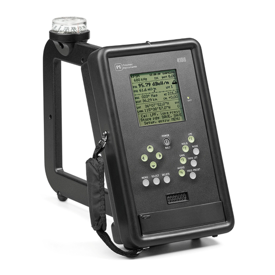
- Page 2 Battery holder for six AA cells About the packing material: Save the box and foam insert for use when returning the PI 4100 for calibration or repair. See the User's Guide or www.pi-usa.com for return procedures. Note that the foam inserts will fit exactly into the PELICAN® 1610 CASE for transport and storage.
- Page 3 PI 4100 Medium Wave Field Strength Meter User’s Guide Operating and Service Instructions Version E, Universal 15 January 2014 Potomac Instruments inc 7309 Grove Road, Unit D, Frederick, MD 21704, USA...
-
Page 4: Table Of Contents
3.2 Primary Display Screen Elements ............3.3 Rear Panel Signal and Power Ports ............15 4. Operation ........................ 4.1 First-Time Operation ................4.2 PI 4100 Operating Procedure Details ............4.2.1 Setting the operating frequency ..........4.2.1.1 Turn-on frequency ……....……………………. 18 4.2.1.2 MENU-Tx select ...………………………………… 18 4.2.1.3 FREQ PRESET ……………………………………. - Page 5 4.4 Battery Information ..................27 4.4.1 Charging the battery ..............27 4.4.2 Loose-cell battery ............... 27 4.5 Data storage and retrieval: The PI 4100 Data Downloader program ..28 4.5.1 General ..................28 4.5.2 Viewing and deleting data using the PI 4100 controls and display..................
-
Page 7: General Description
Distance from the transmitting antenna or array. Line-of-sight distance from the point of measurement to the transmitting source is displayed both for operator feedback and for logging. This feature is enabled when the latitude and longitude coordinates of the source are entered into PI 4100 memory by the operator. -
Page 8: Pi 4100 Key Feature
● External RF output port (BNC) so that the buffered output from the loop antenna can be used to drive external detectors and spectrum display devices ● USB port for downloading data from the PI 4100 internal memory to a compatible computer ● Comma separated data format for ease of importation to third party commercial software ●... -
Page 9: Specifications
1.3 SPECIFICATIONS Field Strength Measurement Frequency Range 520 kHz to 5.1 MHz or 200 kHz to 5.1 MHz, calibrated Minimum frequency step 1.0 kHz Measuring accuracy: AM & Simulcast DRM ± 3 % Pure DRM ± 6 % Field strength measuring range: AM &... - Page 10 RF Voltmeter (RF In jack) Input impedance 2500 Ω Voltage range 30 μV to 40 V rms Measurement units μV-mV-V; mV only; dBuV 28 ±2 mV rms in 50Ω for 1 V/m FS, 200 kHz – 5.1 MHz RF Out DC Field Strength output Proportional to dBuV/m, 1.0 Vdc @ 100 dBuV/m with a 1 MΩ...
- Page 11 Figure 1. PI 4100 Functional Block Diagram...
-
Page 12: Receipt And Inspection
2.2 Reshipment to factory If a PI 4100 must be returned to the factory it is best shipped in its original carton and packing materials or in a Pelican 1610 case. Shipping cartons can be ordered from the factory if suitable packaging is not available. -
Page 13: Controls, Indicators, And External Ports
DELETE: Used to review the data records stored in the PI 4100, and (using SELECT) to delete selected data records. For details see Sec. 4.5.2, p. 27. - Page 14 SAVE/F3: Used to save a measurement and associated data in internal memory. Press once to review and change the associated data on the Save screen, and press again to complete the Save operation and go back to the Field Strength screen. For details see Sec. 4.2.4, p. 19. For F3 see FREQ PRESET. HOLD/F2: When pressed, the field strength value at that time is held on the display and in temporary memory.
-
Page 15: Primary Display Screen Elements
For more detail on an item refer to Sec. 4, Operation. Figure 2. PI 4100 Field Strength display Line 1: Call sign of the selected station; Time and date from GPS (UTC + Offset). -
Page 16: Rear Panel Signal And Power Ports
DC field strength output Buffered antenna RF output USB data port Cal detector dc output Figure 3. PI 4100 Rear Panel Signal and Power Ports Figure 4. Charger Cable installed for charging Figure 5. Battery charger and Interface Cables supplied... -
Page 17: Operation
4. Operation 4.1 FIRST- TIME OPERATION After unpacking the 4100, a trial run will help a new user to become familiar with its operation. The following is suggested: Connect and charge the supplied battery pack, if either is necessary. ... - Page 18 When a USB cable, Type A to Type B, is connected between the computer and the 4100, “PI 4100 connected” appears at the top of the program window and the 4100 display blanks. On the computer click the top “Download...” button; specify the file name of the .csv file that will contain the data and where that file is to be stored.
-
Page 19: Pi4100 Operating Procedure Details
4.2 PI4100 Operating procedure details 4.2.1 Setting the operating frequency: Frequency can be set in these ways: Accept the turn-on setting MENU - Tx select FREQ PRESET key FREQ SET key MENU - Harmonic select 4.2.1.1 Turn-on: A new 4100 turned on for the first time shows the factory setting, 500 kHz. If the unit has been used: if it was on a frequency chosen using Tx select (see below) at turn-off, it will be on that frequency when next turned on. -
Page 20: Enter Station Data Using Menu - Tx Add
4.2.2.1 To enter station data using MENU – Tx add: Press POWER/BKLT to turn on the 4100. Press MENU after the field strength screen appears; the menu screen appears. Press the Down arrow key to go to Tx add; press SELECT. The Tx data entry screen appears, listing six data items to be entered, and with the reverse video cursor on the first item, Call - Site. -
Page 21: Self-Calibration, Automatic And Manual
4.2.3 Self-calibration, automatic and manual Automatic calibration: The 4100 calibrates itself using an internal calibrating source. This takes place automatically when the unit is turned on, and also when the selected station is changed by using Tx select or FREQ PRESET. Manual calibration: To initiate calibration at any time press LPF, holding the key down until a blinking CAL message appears on the display, followed by CAL OK. -
Page 22: Completing The Save
Save screen the number of measurements that can be saved at any time is given as NNN Free. To reduce the possibility of data loss it is advisable to download saved data as soon as possible, using the PI 4100 Data Downloader program supplied (see Sec. -
Page 23: Dc Field Strength Output
AM field strengths, up to and beyond the recommended limits for worker exposure, 600 V/m at or below 1 MHz and (600/f in MHz) above 1 MHz. Potomac Instruments strongly recommends that 4100 users stay within these limits. In high field work, near an antenna tower, electric field strength readings... -
Page 24: Frequency Range For Measurements
1.7 MHz are possible. 4.2.6 Measuring Harmonics 4.2.6.1 Measurement conditions: The PI 4100 can measure broadcast harmonics with full accuracy for harmonic frequencies up to 5.1 MHz and with reduced accuracy to 8.5 MHz. For accurate measurements the received signal must be large enough that the harmonic to be measured will be above the 4100’s noise floor, but not large enough to cause significant harmonic generation within the 4100. -
Page 25: Measuring Rf Voltage: The Rf In Bnc Jack
4.2.8 Measuring RF voltage: the RF In BNC jack General: The PI 4100 can serve as a tuned RF voltmeter to measure the level of a signal connected to its RF In BNC jack, with approximately ±5 per cent accuracy over a range of 30 microvolts (32 dBuV) to 40 Volts (151 dBuV). -
Page 26: Menu Operation Reference
4.3 MENU Operation reference 4.3.1 Menu Navigation: Use the menu to choose options and enter data as indicated below for each item. Press MENU and follow the directions at the bottom of each screen or the instructions below. For all items, use the up and down arrow keys to move the reverse video cursor to the desired item, and then do the following: For items showing two or more options with one option underlined, use the right and left arrow keys to move the underline to the desired option. - Page 27 UTC offset: +NNhNNm Use to enter the time interval (offset) in hours and minutes which must be added to UTC time to enable the display to show local time correctly when a GPS fix is obtained. To set the interval, move the cursor to UTC offset and follow on-screen instructions.
-
Page 28: Battery Information
4.4 Battery information General: The PI4100 is supplied with a rechargeable battery pack made up of six matched nickel-metal hydride (NiMH) AA size cells. Included in the pack is a temperature sensor which connects to the charging circuit to prevent charging when the temperature is too high or too low. When the pack reaches the end of its useful life, as indicated by a decreasing number of measurements possible per charge, it is recommended to replace it with an identical pack from the factory. -
Page 29: Data Storage And Retrieval: The Pi 4100 Data Downloader Program
4.5.2 Viewing and deleting data using the PI 4100 controls and display: To view data records on the PI 4100 display, press the DELETE key; data items from the last record stored appear. The data items shown are Data point, Date, Time, Frequency, Azimuth, Pattern, Distance, and Field Strength (FS1). -
Page 30: Data Downloader Program Operation
4.5.5 Data Downloader program operation: ●To open the program click the PI icon, or click Start - Programs - Potomac Instruments - PI4100 Data Downloader. The PI4100 Data Downloader window should appear (Fig. 6, appearance may differ for different Windows versions). If the 4100’s USB cable is not yet connected, the title bar of the box shows PI 4100 Not Connected and the selection buttons do not function. -
Page 31: Data Record Fields
4.5.6 Data record fields: The data record for each measurement contains 31 fields, listed below in the order in which they appear in the .csv file. For details on any item , go to the applicable section of this User’s Guide. Dir ID Internal use only Rec ID... -
Page 32: Service Information
It is also possible to contact the factory directly (see Contact information below) with the problem description in as much detail as possible. ●Repair: The PI 4100 is not considered field repairable, except that some minor repairs and possibly module replacement can be done at an authorized service facility. Future problems are less likely when all but the simplest repairs are done at the factory, especially if they involve opening the unit.. -
Page 33: Calibration
5.4 PI 4100 Calibration Verification Test General: The purpose of this procedure is to verify that a particular PI 4100 Field Strength Meter continues to perform in accordance with its published specifications and its factory calibration. The test makes use of the 4100’s external connectors and loop antenna and requires an external signal generator and a precision voltmeter. - Page 34 Supplied Data Sheet: A Calibration Data Sheet is included on the CD-ROM supplied with the PI 4100. It is a Microsoft Excel file, PI4100FieldCalCheckDataSheet2.xls, for downloading to a user’s Windows computer. To use it, for each frequency enter the following: in Column B, the factory indicated field strength for the unit from the supplied calibration certificate;...
- Page 35 4b. Turn on the 4100 and set it to the same frequency, 520 kHz, using the FREQ SET key as described in the PI 4100 Users Manual. The field strength reading should be in the neighborhood of 700 mV/m and the dc voltmeter reading should be in the neighborhood of 700 mV.
- Page 36 ●Connect a DVM to read the dc voltage at the RF Out jack. Adjust the generator output level for a DVM reading as close as possible to 700 mVdc. ●Press MENU, go to Input and select RF In. The 4100 voltage reading should be 700 ± 35 mV.
-
Page 37: Contact Information
5.5 Contact information Factory: Potomac Instruments inc. Attn: Service Dept. 7309 Grove Road, Unit D Frederick, MD (Maryland) 21704 Phone: +1 - 301 - 696 - 5550 Fax: +1 - 301 - 696 - 5553 email: service@pi-usa.com Time zone: North American Eastern, UMT-5 Web site: www.pi-usa.com... -
Page 38: Technical Information
6. Technical Information 6.1 Introduction This section contains a description of the PI 4100’s circuits with reference to its printed circuit boards as shown on the System Block Diagram, Fig. 1, p. 10. This is followed by schematic diagrams and component layout drawings for the printed circuit boards manufactured by Potomac Instruments. - Page 39 GPS: The GPS pcb and its receiver module are products of the u-blox AG company, which is known for its advanced GPS receiver ICs. The pcb is fed by a ceramic antenna located at the top of the PI 4100’s case.
- Page 40 Figure 8 CPU Board layout...
- Page 41 Figure 9 CPU Board schematic...
- Page 42 Figure 10 Receiver Board layout...
- Page 43 Figure 11 Receiver Board schematic...
- Page 44 Figure 12 Power/Audio Board layout...
- Page 45 Figure 13 Power/Audio Board schematic...
-
Page 46: Appendix 1: Using The Magnetic Compass Of The Pi 4100
Since certain measurements will be made when the transmitting antenna is not visible to the operator, a magnetic compass is supplied as an integral component of the PI 4100 and it can be used for approximating the direction of proper antenna alignment. - Page 47 (This page left blank)
-
Page 48: Appendix 2: Pi 4100 Operation Quick Reference
Appendix 2 PI 4100 OPERATION QUICK REFERENCE The 4100 has on-screen help for most operations. In the menu use up & down arrow keys to go to an item. To select a digit to change use left & right arrow keys. To change the digit value use up & down arrow keys Turn the 4100 on: Press POWER/BKLT until text appears. -
Page 49: Appendix 3: Sample Excel Field Strength Measurements Report
View a spectrum showing absolute field strength: Press MODE three times. Change the spectrum span (sweep width): Press MENU, go to Spectrum kHz: 128 45, follow on- screen help. Go to the field strength screen from a spectrum screen: Repeat presses of MODE until the field strength screen appears. - Page 50 1) Copy the Excel® file 4100 Data Report.xlt to your default Excel folder or as deemed appropriate 2) Start Excel 3) From within Excel, open the desired PI 4100 data file (xxxxxx.csv) 4) Move the cursor to highlight cell A1...
- Page 51 Figure 14. PI 4100 Data Report Template...
-
Page 52: Appendix 4: Pi 4100 Accessories
PI 4100. It is available from Potomac Instruments. ●Charging Cable, Part No. LM10541: A cable which plugs into a vehicle's cigarette lighter socket and the PI 4100's charging jack, identical to the one supplied with the unit. It is available from Potomac Instruments. - Page 56 7309 Grove Road Unit D Frederick, MD 21704, USA +1-301-696-5550 http://www.pi-usa.com PI 4100 User’s Guide...
Need help?
Do you have a question about the PI 4100 and is the answer not in the manual?
Questions and answers