Table of Contents
Advertisement
maxon motor control
Operating Instructions
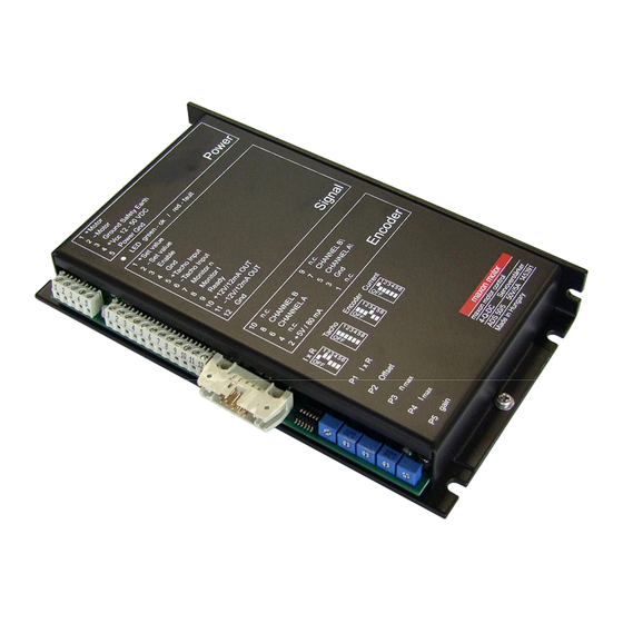
The ADS 50/5 is a powerful servoamplifier for
driving permanent magnet DC motors up to
250 Watts.
Four modes can be selected by DIP switches
on the board:
•
Speed control using tacho signals
•
Speed control using encoder signals
•
IxR compensated speed control
•
Torque or current control
The ADS 50/5 is protected against excess
current,
excess temperature and short circuit on the
motor winding. With the FET power transis-
tors incorporated in the servoamplifier, an
efficiency of up to 95 % is achieved. A built in
motor choke combined with the high PWM
frequency of 50 kHz allows the connection of
motors with a very low inductivity. In most
cases an external choke can be omitted.
Thanks to the wide input power supply range of 12 - 50 VDC, the ADS 50/5 is very versatile and can be used
with various power supplies. The aluminium housing makes installation simple, with terminal markings for easy
connection.
Table of Contents
1
Safety Instructions ........................................................................................................................................... 2
2
Performance Data............................................................................................................................................ 3
3
Minimum External Wiring for Different Modes of Operation ............................................................................ 4
4
Operating Instructions...................................................................................................................................... 5
5
Functions ......................................................................................................................................................... 7
6
Additional Possible Adjustments.................................................................................................................... 10
7
Operating Status Display ............................................................................................................................... 12
8
Error Handling................................................................................................................................................ 13
9
EMC-compliant installation ............................................................................................................................ 13
10 Block Diagram................................................................................................................................................ 14
11 Dimension Drawing........................................................................................................................................ 14
The latest edition of these operating instructions may be downloaded from the internet as a PDF-file under
www.maxonmotor.com, category «Service & Downloads», order number 145391 or
in the e-shop http://shop.maxonmotor.com.
maxon motor
4-Q-DC Servoamplifier ADS 50/5
Order number 145391
July 2009 Edition
Advertisement
Table of Contents

Subscribe to Our Youtube Channel
Related Manuals for maxon motor ADS 50/5


Summary of Contents for maxon motor ADS 50/5
-
Page 1: Table Of Contents
Thanks to the wide input power supply range of 12 - 50 VDC, the ADS 50/5 is very versatile and can be used with various power supplies. The aluminium housing makes installation simple, with terminal markings for easy connection. -
Page 2: Safety Instructions
Danger Do ensure that during the installation of the ADS 50/5 no apparatus is connected to the electrical supply. After switching on, do not touch any live parts. -
Page 3: Performance Data
4-Q-DC Servoamplifier ADS 50/5 Operating Instructions Performance Data 2.1 Electrical data Nominal supply voltage +V ..................12 … 50 VDC Absolute minimum supply voltage +V ..............11.4 VDC cc min Absolute maximum supply voltage +V ..............52.5 VDC cc max Max. -
Page 4: Minimum External Wiring For Different Modes Of Operation
4-Q-DC Servoamplifier ADS 50/5 Operating Instructions Minimum External Wiring for Different Modes of Operation maxon motor control July 2009 Edition / Doc. No. 538837-07 / Subject to change... -
Page 5: Operating Instructions
4-Q-DC Servoamplifier ADS 50/5 Operating Instructions Operating Instructions 4.1 Determine power supply requirements You may make use of any available power supply, as long as it meets the mi- nimal requirements spelled out below. During set up and adjustment phases, we recommend separating the motor mechanically from the machine to prevent damage due to uncontrolled motion. - Page 6 4-Q-DC Servoamplifier ADS 50/5 Operating Instructions 4.3 Adjustment of the Potentiometers 4.3.1 Pre-adjustment With the pre-adjustment, the potentiometers are set in a preferred position. ADS units in original packing are already pre-adjusted. Pre-adjustment of potentiometers Offset 50 %...
-
Page 7: Functions
4-Q-DC Servoamplifier ADS 50/5 Operating Instructions Functions 5.1 Inputs 5.1.1 Set value The set value input is wired as a differential amplifier. Input voltage range -10 ... +10 V Input circuit differential Input resistance 20 kΩ (differential) Positive set value ( + Set value) >... - Page 8 4-Q-DC Servoamplifier ADS 50/5 Operating Instructions 5.1.4 Encoder Encoder supply voltage + 5 VDC max. 80 mA Maximum encoder frequency DIP switch S5 ON: 10 kHz DIP switch S5 OFF: 100 kHz Voltage value max. 0.8 V high min.
- Page 9 4-Q-DC Servoamplifier ADS 50/5 Operating Instructions 5.2 Outputs 5.2.1 Current monitor “Monitor I” The servoamplifier makes a current actual value available for monitoring pur- poses. The signal is proportional to the motor current. The “Monitor I” output is short-circuit protected.
-
Page 10: Additional Possible Adjustments
4-Q-DC Servoamplifier ADS 50/5 Operating Instructions Additional Possible Adjustments Potentiometer Function Position left right speed gain high gain current gain high gain continuous current limit lower higher cont P8 I cont P7 I gain P6 n gain 6.1 Adjustments potentiometer P6 n... - Page 11 4-Q-DC Servoamplifier ADS 50/5 Operating Instructions 6.2 Adjustments potentiometer P8 I and current limit mode DIP switch S6 cont It is standard that a maximum current limiter is activated (DIP switch S6 OFF). In this way the motor current is limited to the value set on potentiometer P4 I (0.5 ...
-
Page 12: Operating Status Display
4-Q-DC Servoamplifier ADS 50/5 Operating Instructions Operating Status Display A two coloured red/green LED shows the operating mode. 7.1 No LED Reason: • No supply voltage • Fuse fault • Wrong polarity of supply voltage • Short circuit of the +5 V output 7.2 LED shines green... -
Page 13: Error Handling
• Use separate cable. Encoder cable • Although the ADS 50/5 can also be operated without a line driver, using an encoder with a line driver is recommended as this improves interference resistance. • No shielding normally required. •... -
Page 14: Block Diagram
4-Q-DC Servoamplifier ADS 50/5 Operating Instructions 10 Block Diagram Case +12V OUT -12V OUT Enable Ready Poly- DIP5 Ground fuse +5V/80mA Safety +12V Earth +12V -12V Supply -12V Encoder A earth optional F/V Converter Encoder A\ +Vcc 12-50VDC...
Need help?
Do you have a question about the ADS 50/5 and is the answer not in the manual?
Questions and answers