
Related Manuals for Walther E-boxx 780001502

Summary of Contents for Walther E-boxx 780001502
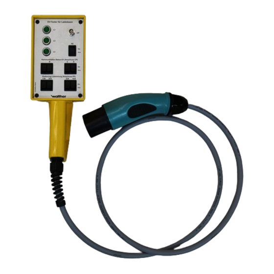
- Page 1 Operating instruction and technical description EV tester / EV simulator with charging plug type 2 for charging devices Photos: EV tester/simulator with charging plug type 2...
- Page 2 4.4 Checking the PE connection between PWM and vehicle 4.5 Simulation of vehicle status B, C, D 4.6 Measuring of PWM signal (CP test jack) 5 Troubleshooting 6 Maintenance 7 General technical specifications © Walther-Werke Ferdinand Walther GmbH page 2 of 10...
-
Page 3: Safety Notes
Do not touch live parts. Use insulated tools. Never touch electric cables with wet hands. The plant must not be permanently exposed to rain or humidity. © Walther-Werke Ferdinand Walther GmbH page 3 of 10... -
Page 4: Operating Instructions
In each case it only comes to a small power drain of approx. 3 mA for L1, L2 and L3 from the connected charging device. The simulation is only possible when the device is connected. Photos: EV tester/simulator for type 2 Photo: EV tester/simulator for type 1 © Walther-Werke Ferdinand Walther GmbH page 4 of 10... - Page 5 • Establish the electrical connection of the EV tester. Check the correct supply as well as the earth protection prior to operating the unit. • For operating the EV tester there s no supply required. If anything is unclear, please contact the supplier. © Walther-Werke Ferdinand Walther GmbH page 5 of 10...
-
Page 6: Operation
The table shows that the different switch positions (charging cable coding (connection PP)) are simulating the cable cross section of the utilised charging cable. Normally, the maximum charging current is limited by the utilised cable cross section. Photo: switch for charging cable coding © Walther-Werke Ferdinand Walther GmbH page 6 of 10... - Page 7 By operating switch B the vehicle status B is simulated. In this status the electric vehicle is connected to the charging device and is ready to be charged (PWM signal: 9 V). © Walther-Werke Ferdinand Walther GmbH page 7 of 10...
-
Page 8: Troubleshooting
Check switch positions communication status EV nected to the BNC fe- correctly (CP connection) B,C,D male jack delivers no signal Check switch position PE. Switch positions are wrong Check BNC plug. © Walther-Werke Ferdinand Walther GmbH page 8 of 10... -
Page 9: Maintenance
Power supply 230 V / 400 V single- or three-phase 50 Hz / 60 Hz Charging cable 7G2,5 Cable length approx. 1,5 m Plug type 2 7-pole plug, acc. to IEC 62196 © Walther-Werke Ferdinand Walther GmbH page 9 of 10... - Page 10 Operating instruction and technical description BA EV tester type 2 - 2.0 © Walther-Werke Ferdinand Walther GmbH page 10 of 10...
Need help?
Do you have a question about the E-boxx 780001502 and is the answer not in the manual?
Questions and answers