Table of Contents
Advertisement
AL Driver series
1
1
s e
s e
F u
F u
A
A
V / 8
V / 8
I N
I N
2 5 0
2 5 0
D M
D M
X / R
X / R
D M
D M
3
3
2
2
T
T
O U
O U
1
1
D M
D M
X / R
X / R
3
3
2
2
D M
D M
1
1
A +
A +
A T
A T
= D
= D
- 3
- 3
T A
T A
D A
D A
D A
D A
D A
D A
2 =
2 =
s e
s e
F u
F u
n d
n d
A
A
3
3
D
D
V / 8
V / 8
r o u
r o u
G N
G N
2 5 0
2 5 0
1 = G
1 = G
0 V
0 V
1 - 1
1 - 1
0 V /
0 V /
0 - 1
0 - 1
N
N
L I I
L I I
D A
D A
I N
I N
O G
O G
A L
A L
A N
A N
2
2
s e
s e
F u
F u
A
A
V / 8
V / 8
2 5 0
2 5 0
s e
s e
F u
F u
A
A
V / 8
V / 8
4
4
2 5 0
2 5 0
User guide
Advertisement
Table of Contents

Related Manuals for Acclaim Lighting AL Driver series

Summary of Contents for Acclaim Lighting AL Driver series
- Page 1 2 5 0 2 5 0 1 = G 1 = G 1 - 1 1 - 1 0 V / 0 V / 0 - 1 0 - 1 L I I L I I AL Driver series User guide...
-
Page 3: Table Of Contents
CONTENTS INTRODUCTION ............2 Welcome Safety INSTALLATION ............3 Mounting Input connections Output port connections Output port fuses Input power wiring Connector cover AL Driver 1 AL Driver 4 OPERATION (200/400/800) ........12 Menu navigation Choosing a control mode AL Driver 200 - Channel and load settings (DMX and DALI) AL Driver 400 - Channel and load settings (DMX and DALI) AL Driver 800 - Channel and load settings (DMX and DALI) Choosing a base address (DMX and DALI) -
Page 4: Introduction
INTRODUCTION WELCOME Welcome to the AL Driver series from Acclaim Lighting, a comprehensive range of constant voltage drivers which support a variety of LED fixture types: RGBW, RGB, Ai Dim, single color or Dynamic White. The entry level to the range is fulfilled by the highly compact AL Driver 1 with its single-port to drive one-color LED tapes. -
Page 5: Installation
INSTALLATION The majority of this guide covers the multi-port AL Driver 200, AL Driver 400 and AL Driver 800 models. For details about the single port AL Driver 1 and AL Driver 4 models, please see pages 8 and10 respectively. MOUNTING The AL Driver 200, 400 and 800 models can be wall mounted either vertically (with the output connectors facing downwards) or horizontally as required. -
Page 6: Al Driver
DALI AL Drivers have a single DALI port that uses a 2-pin terminal block (supplied). For best results always use mains rated cables with 600V isolation and core with at least 1mm cross section. DALI signals are not polarity dependent and so can be connected either way round: Insert the terminal block into the DALI IN 2 5 0 X / R... -
Page 7: Output Port Connections
OUTPUT PORT CONNECTIONS AL Drivers have multiple constant voltage output ports, each of which uses 6-pin terminal block. The output ports use a common anode supply and there are two V+ contacts to assist with multiple fixture i t e connections (the two contacts are joined internally so either or both can be used, as B l u... -
Page 8: Output Port Fuses
OUTPUT PORT CONNECTION CABLES The connection cables (not supplied) used to link the output ports to the fixtures should follow these guidelines (based on a maximum load of 6.6A): Conductor size • 18 AWG (0.823mm Up to 40 feet (12m) •... -
Page 9: Connector Cover
CONNECTOR COVER Each AL Driver unit is supplied with a transparent plastic cover to provide protection to the control inputs and port output connections. TO FIT THE CONNECTOR COVER 1 Insert the angled upper lip of the cover into the slot at the top of the connector panel. V / 8 2 5 0 V / 8... - Page 10 AL DRIVER 1 The AL Driver 1 module controls one circuit of single color LED tape, either under control of an external DMX digital signal, an external 0-10V/1-10V analog signal or using standalone intensity mixes. The AL Driver 1 is a constant voltage device and can operate from DC power supplies ranging from 6 to 24VDC (5A maximum);...
- Page 11 CONFIGURATION The AL Driver 1 is configured using its 12 way switch block. The two main modes of operation are external control or standalone dimming. EXTERNAL CONTROL To select external control, ensure that switch 10 is ON. Note: The DMX and analog (0-10V/1- 10V) inputs are both active in this mode, so it is important that only one set of inputs are connected at any one time: either DMX OR analog.
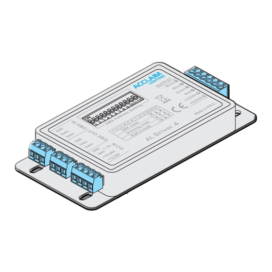
- Page 12 AL DRIVER 4 The AL Driver 4 module controls a single circuit of RGB or RGBW LED tape, either under control of an external DMX signal or using standalone color mixes or chase patterns. The AL Driver 4 is a constant voltage device and can operate from DC power supplies ranging from 12 to 24VDC;...
- Page 13 CONFIGURATION The AL Driver 4 is configured using its 12 way switch block. The three modes of operation are external DMX control, standalone color mixing or standalone chases. DMX CONTROL To select DMX control, ensure that switch 10 is ON, while 11 and 12 are OFF.
-
Page 14: Operation (200/400/800)
OPERATION (200/400/800) AL Drivers begin operating as soon as power is applied, there are no power switches. MENU NAVIGATION Use the three control buttons to navigate around the menu and alter settings as necessary. The display has a backlight timeout and will go dark roughly 30 seconds after the last button press - tap any key to restore. - Page 15 MAIN MENU ITEMS (WHEN MODE SET TO DMX512) Determines the control method to be used. Options are: DMX512, DALI, MODE DMX512 1-10V, 0-10V, MANUAL and AUTO. See page 18. Selects the nature of the LED loads that will be placed on the output ports: LOAD RGBW Options are RGB, RGBW, Ai Dim, WHITE and DW.
- Page 16 MAIN MENU ITEMS (WHEN MODE SET TO DALI) Determines the control method to be used. Options are: DMX512, 1-10V, MODE 0-10V, MANUAL and AUTO. See page 18. DALI Selects the nature of the LED loads that will be placed on the output ports: LOAD Options are RGB, RGBW, Ai Dim, WHITE and DW.
- Page 17 MAIN MENU ITEMS (WHEN MODE SET TO 0-10V OR 1-10V) Determines the control method to be used. Options are: DMX512, DALI, MODE 1-10V, 0-10V, MANUAL and AUTO. See page 18. 0-10V Selects the nature of the LED loads that will be placed on the output ports: LOAD Options are WHITE, Ai Dim and DW.
- Page 18 MAIN MENU ITEMS (WHEN MODE SET TO MANUAL) Determines the control method to be used. Other options are: DMX512, MODE DALI, 1-10V, 0-10V, and AUTO. See page 18. MANUAL Selects the nature of the LED loads that will be placed on the output ports: LOAD Options are RGB, RGBW, Ai Dim, WHITE and DW.
- Page 19 MAIN MENU ITEMS (WHEN MODE SET TO AUTO) Determines the control method to be used. Other options are: DMX512, MODE DALI, 1-10V, 0-10V and MANUAL. See page 18. AUTO Selects the nature of the LED loads that will be placed on the output ports: LOAD Options are RGB, RGBW, Ai Dim, WHITE and DW.
-
Page 20: Choosing A Control Mode
CHOOSING A CONTROL MODE AL Drivers have six control modes: • DMX512 - Port output levels are determined by the signal received at the DMX/RDM IN connector. • DALI - Port output levels are determined by the signal received at the DALI IN connector. -
Page 21: Al Driver 200 - Channel And Load Settings (Dmx And Dali)
AL DRIVER 200 - CHANNEL AND LOAD SETTINGS (DMX AND DALI) When either the DMX or DALI modes are selected, you can determine how the four ports are grouped and applied to the control addresses using the CHANNEL setting. Together with the LOAD setting (which determines how the contacts of each port are used: RGB, RGBW, Ai Dim, etc.), these two key settings determine the total number of control addresses required. -
Page 22: Al Driver 400 - Channel And Load Settings (Dmx And Dali)
AL DRIVER 400 - CHANNEL AND LOAD SETTINGS (DMX AND DALI) When either the DMX or DALI modes are selected, you can determine how the six ports are grouped and applied to the control addresses using the CHANNEL setting. Together with the LOAD setting (which determines how the contacts of each port are used: RGB, RGBW, Ai Dim, etc.), these two key settings determine the total number of control addresses required. -
Page 23: Al Driver 800 - Channel And Load Settings (Dmx And Dali)
AL DRIVER 800 - CHANNEL AND LOAD SETTINGS (DMX AND DALI) When either the DMX or DALI modes are selected, you can determine how the ten ports are grouped and applied to the control addresses using the CHANNEL setting. Together with the LOAD setting (which determines how the contacts of each port are used: RGB, RGBW, Ai Dim, etc.), these two key settings determine the total number of control addresses required. -
Page 24: Choosing A Base Address (Dmx And Dali)
CHOOSING A BASE ADDRESS (DMX AND DALI) When DMX or DALI modes are chosen, you need to set a base address at which the AL Driver should begin applying its various output channels. • DMX addresses run from 1 to 512 •... -
Page 25: Setting A Static Color Mix (Manual Mode)
SETTING A STATIC COLOR MIX (MANUAL MODE) Manual mode allows you to create a static color mix across all ports of the AL Driver, independently of any external control input. The available mix options will alter depending on the connected fixture type and the setting of the LOAD option within the Manual section. -
Page 26: Configuration Via Rdm
• Configure the DMX address, • Set the control mode. Various third party DMX/RDM tools are available; Acclaim Lighting recommends the XMT-350. CONFIGURING THE DMX ADDRESS VIA RDM While it is not possible to alter the Channel groupings or Load types remotely via RDM, it is possible to change the DMX base address. - Page 27 DMX PERSONALITY entry: AL DRIVER 200 LABEL: AL DRIVER 200 MODEL: AL DRIVER 200 MAN: ACCLAIM LIGHTING DMX START ADDRESS: DMX PERSONALITY: DMX512 DMX SLOTS: 5 Press the button to view the options: AL DRIVER 200 004 CH...
-
Page 28: Al Driver 200 - Dmx/Dali Address Layouts
AL DRIVER 200 - DMX/DALI ADDRESS LAYOUT (LOAD: RGBW) This chart shows how the channels of each port are distributed across the DMX or DALI addresses for each CHANNEL setting when the LOAD is set to RGBW. The first port(s) (shown in the table below against address 1) will be placed at the base address determined by the DMX or DALI menu options (see page 22). -
Page 29: Al Driver 400 - Dmx/Dali Address Layouts
AL DRIVER 200 - DMX/DALI ADDRESS LAYOUT (LOAD: RGB) This chart shows how the channels of each port are distributed across the DMX or DALI addresses for each CHANNEL setting when the LOAD is set to RGB. The first port(s) (shown in the table below against address 1) will be placed at the base address determined by the DMX or DALI menu options (see page 22). - Page 30 AL DRIVER 200 - DMX/DALI ADDRESS LAYOUT (FOR LOAD: AI DIM, WHITE & DW) This chart shows how the channels of each port are distributed across the DMX or DALI addresses for each CHANNEL setting when the LOAD is set to Ai Dim, WHITE or DW. The first port(s) (shown in the table below against address 1) will be placed at the base address determined by the DMX or DALI menu options (see page 22).
- Page 31 AL DRIVER 400 - DMX/DALI ADDRESS LAYOUT (LOAD: RGBW) This chart shows how the channels of each port are distributed across the DMX or DALI addresses for each CHANNEL setting when the LOAD is set to RGBW. The first port(s) (shown in the table below against address 1) will be placed at the base address determined by the DMX or DALI menu options (see page 22).
- Page 32 AL DRIVER 400 - DMX/DALI ADDRESS LAYOUT (LOAD: RGB) This chart shows how the channels of each port are distributed across the DMX or DALI addresses for each CHANNEL setting when the LOAD is set to RGB. The first port(s) (shown in the table below against address 1) will be placed at the base address determined by the DMX or DALI menu options (see page 22).
- Page 33 AL DRIVER 400 - DMX/DALI ADDRESS LAYOUT (FOR LOAD: AI DIM, WHITE & DW) This chart shows how the channels of each port are distributed across the DMX or DALI addresses for each CHANNEL setting when the LOAD is set to Ai Dim, WHITE or DW. The first port(s) (shown in the table below against address 1) will be placed at the base address determined by the DMX or DALI menu options (see page 22).
-
Page 34: Al Driver 800 - Dmx/Dali Address Layouts
AL DRIVER 800 - DMX/DALI ADDRESS LAYOUT (LOAD: RGBW) This chart shows how the channels of each port are distributed across the DMX or DALI addresses for each CHANNEL setting when the LOAD is set to RGBW. The first port(s) (shown in the table below against address 1) will be placed at the base address determined by the DMX or DALI menu options (see page 22). - Page 35 AL DRIVER 800 - DMX/DALI ADDRESS LAYOUT (LOAD: RGB) This chart shows how the channels of each port are distributed across the DMX or DALI addresses for each CHANNEL setting when the LOAD is set to RGB. The first port(s) (shown in the table below against address 1) will be placed at the base address determined by the DMX or DALI menu options (see page 22).
- Page 36 AL DRIVER 800 - DMX/DALI ADDRESS LAYOUT (FOR LOAD: AI DIM, WHITE & DW) This chart shows how the channels of each port are distributed across the DMX or DALI addresses for each CHANNEL setting when the LOAD is set to Ai Dim, WHITE or DW. The first port(s) (shown in the table below against address 1) will be placed at the base address determined by the DMX or DALI menu options (see page 22).
-
Page 37: Further Information
FURTHER INFORMATION AL DRIVER 1 AND 4 - SPECIFICATIONS Control input protocols DMX (or 0-10V/1-10V - AL Driver 1 only) Control output protocol Pulse width modulation (PWM) Input voltage/current AL Driver 1: 6 to 24VDC (5A maximum) AL Driver 4: 12VDC (8A max.) to 24VDC (4A max.) Output voltage As per input voltage Operating temperature... -
Page 38: Al Driver 1 And 4 - Dimensions
AL DRIVER 1 - DIMENSIONS DMX A DDRESS ETTING Data - 0-10V/1-10V Data + 1.57" 2 3 4 5 6 7 8 9 0-10V/1-10V Data - 1 2 3 4 5 6 7 8 9 10 11 12 (40mm) DC 6-12V/5A, DC 24V/4A(+) Data + DC 6-24V... -
Page 39: Al Driver 200 - Dimensions
AL DRIVER 200 - DIMENSIONS 0.31" (8mm) 0.55" (14mm) A L D R I V E R 2 0 0 2 4 V DALI DMX/RDM 0-10V POWER DOWN 3.58" (91mm) 2.76" (70mm) 6.3" (160mm) Weight: 3.96 lbs (1.8kg) www.acclaimlighting.com... -
Page 40: Al Driver 400 - Dimensions
AL DRIVER 400 - DIMENSIONS 0.31" (8mm) 0.55" (14mm) A L D R I V E R 4 0 0 2 4 V DALI DMX/RDM 0-10V POWER DOWN 5.91" (150mm) 3.15" (80mm) 9.06" (230mm) Weight: 8.4 lbs (3.8kg) www.acclaimlighting.com... -
Page 41: Al Driver 800 - Dimensions
AL DRIVER 800 - DIMENSIONS 0.31" (8mm) 0.55" (14mm) A L D R I V E R 8 0 0 2 4 V DALI DMX/RDM 0-10V POWER DOWN 8.7" (220mm) 4" (100mm) 10.7" (270mm) Weight: 14.4 lbs (6.5kg) www.acclaimlighting.com... -
Page 42: Limited Product Warranty
If the requested repairs or service (including parts replacement) are within the terms of this warranty, Acclaim Lighting will pay return shipping charges only to a designated point within the United States. If the entire instrument is sent, it must be shipped in its original package. - Page 43 www.acclaimlighting.com...
- Page 44 www.acclaimlighting.com...
Need help?
Do you have a question about the AL Driver series and is the answer not in the manual?
Questions and answers