
Subscribe to Our Youtube Channel
Related Manuals for Trocen AWC708C Plus

Summary of Contents for Trocen AWC708C Plus
- Page 1 AWC708 Plus Motion Control User Manual Laser Motion Control RV 1.4 2017.06 www.sztrocen.com Copyright © 2016 Trocen Automation Tech. Co. Ltd. All rights reserved.
- Page 2 Copyright TROCEN AUTOMATION TECHNOLOGY CO. LTD. Patent Trocen has held the patent rights for our laser motion control. Users have the responsibility to point out the design error and establish Attention! protection mechanisms. Trocen does not accept any responsibility or liability for any damage or loss resulting from improper operation.
-
Page 3: Table Of Contents
Contents Outline ..............................1 Terms............................1 Snapshot............................1 LaserCAD Installation.........................1 Hardware Installation.......................... 1 Hardware Parts..........................1 Accessories..........................1 Panel............................ 2 Overview of Panel.......................2 Size of Panel........................3 Wiring Board........................3 Overview of Wiring Board..................3 Size of Wiring Board....................4 Electric Connection........................4 Wiring Diagram........................4 Explanation About Unit Port and Wiring Diagram of Wiring Board......... -
Page 4: Outline
I/O with control card of driver. Hardware Including panel, wiring board and accessories Snapshot AWC708 Plus series, high efficiency in production, invented by Trocen for around 5 years, combines LaserCAD with controller and reduce product costs. Features of LaserCAD: User-friendly and versatile ... -
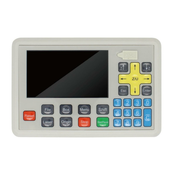
Page 5: Panel
Network Connect computer and panel. Cable CN1&CN2 as one set to connect wiring board and Cables panel. Extension Extension cords allow for long distance between Cords USB and network cable. Panel Overview of Panel... -
Page 6: Size Of Panel
Size of Panel Wiring Board Wiring board plays a role of connecting panel and other parts, including: Connecting to driver Detection of limit signal from axis Detecting input signal I/O signal and corresponding power supply unit Overview of Wiring Board... -
Page 7: Size Of Wiring Board
Size of Wiring Board Electric Connection Wiring Diagram Explanation About Unit Port and Wiring Diagram of Wiring Board Power Supply Port on Wiring Board The power supply for wiring board and panel and pay more attention to polarity when you are connecting them. -
Page 8: Port Of Panel And Wiring Board
Port No. Title Explanation 24V positive polarity 24V grounding Port of Panel and Wiring Board Connect panel to wiring board with CN cables. Title Explanation Connect CN1 to panel Connect CN2 to panel Signal Input Port on Wiring Board There are two ports for signal input. Ports Title Explanation... -
Page 9: I/O On Wiring Board
Wiring diagram for signal input: IN1: Open Cover Protection IN2: Foot Switch I/O on Wiring Board There are two output ports for power supply outside and signal control. Ports Title Explanation 1.OUT OUT1 Blow signal (blowing all the working time) OUT1 Blow when output is high logic level OUT1 Do not blow when output is low logic level OUT2... -
Page 10: Laser Power Supply Port On Wiring Board
Output signal generally controls laser blowing and the wiring diagram shown below. Laser Power Supply Port on Wiring Board There are two output ports on wiring board. Ports Title Explanation 5.LASER2 5V power supply positive output 6.LASER1 Water protection input signal Laser power Laser on/off signal Grounding output... -
Page 11: Driver Port On Wiring Board
Here’s one road of laser’s wiring diagram as an example. Driver Port on Wiring Board There are no more than 4 roads for driver connection on wiring board. Port Title Explanation X/Y/ DC5V 5V power supply positive polarity connecting to driver’s positive polarity Pulse signal Direction signal... -
Page 12: Input Port Of Limit Signal On Wiring Board
Input Port of Limit Signal on Wiring Board 6 roads of limit signal of sensor on wiring board. 2 limit signals input on two side of each axis. X/Y Limit Signal Input Port Title Explanation 8.X/Y DC24V 24V power supply positive polarity output LIMIT ELY+ Y+ limit switch/input signal from sensor... - Page 13 Wiring Diagram: Limit Switch ELY+: Limit switch another side opposite to origin on Y axis. ELY-: Limit switch on origin on Y axis.
Need help?
Do you have a question about the AWC708C Plus and is the answer not in the manual?
Questions and answers