
Summary of Contents for Steca TR-A501T-U
- Page 1 Temperature differential controller 5 inputs, 1 output Installation and operating instructions 742.110 | Z03 | 14.50 | Subject to change due to technical improvements!
-
Page 2: Table Of Contents
Contents General safety instructions Proper usage About these instructions Contents Target audience Danger levels in warning notices Évaluation du niveau de risque dans les avertissements 4 Installation Opening/Closing the casing Mounting the casing Establishing the electrical connections Terminal pin assignments Commissioning the device for the first time Structure Casing... -
Page 3: General Safety Instructions
14 Troubleshooting 14.1 General faults 14.2 Error messages 14.3 Checking the Pt1000 temperature sensors 15 Technical data 15.1 Controller 15.2 Cable specifications 16 Exclusion of liability 17 Legal guarantee 18 Notes General safety instructions • This document is part of the product. • Use the device only after reading and understanding this document. -
Page 4: Proper Usage
Proper usage The temperature differential controller, subsequently referred to as the controller, is an independently installed electronic temperature controller for on-surface installation. Integration into a pump assembly is possible when the technical specifications of the controller are adhered to. The maintenance-free controller is exclusively intended for controlling solar and heating systems. -
Page 5: Installation
Installation Note The following section describes only the installation of the controller. Follow the instruc- tions of each respective manufacturer when installing external components (collectors, pumps, storage tanks, valves etc.) Opening/Closing the casing 4.1.1 Remove the front panel ... -
Page 6: Mounting The Casing
Mounting the casing √ The mounting location must satisfy the prescribed conditions of use; see sec- tion 15, p. 45. √ The mounting surface is vertical and allows good access for installation. Danger Risk of death by electrocution! • Disconnect the controller from the power supply before opening the casing. • Make sure that the power supply cannot be unintentionally switched on when the casing is open. -
Page 7: Establishing The Electrical Connections
Establishing the electrical connections Danger Risk of death by electrocution! Make sure that the following conditions are satisfied when performing the work described in this section: • All cables leading to the controller must be disconnected from the power supply and it must be ensured that they cannot be unintentionally reconnected during installa- tion. - Page 8 4.3.1 Position of the connection terminals 0–10 L R1 Fig. 3: Terminal clamps in the lower part of the controller (terminal cover removed) Power connection terminal block: 1x phase conductor (mains input) 1x output (TRIAC, for pump) 2x neutral conductor (common neutral conductors for mains power input and output) Note Output R1 is protected by an electronic fuse.
- Page 9 4.3.2 Preparing the cable openings The cables can be fed through openings in the rear wall of the casing or at the bottom of the casing. The openings are pre-punched and must be prepared as required before installation. Prepare the cable openings in the rear wall of the casing as follows: ...
-
Page 10: Terminal Pin Assignments
Remove the plastic links as follows: 1. Insert a screwdriver under the right plastic link between the casing and the spring clamp (Fig. 5). 2. Carefully push the screwdriver to the left . Lever the spring clamp ... -
Page 11: Commissioning The Device For The First Time
Display Legend Terminal layout 1 swimming pool, 1 collector array T1: Collector array sensor T2: Swimming pool sensor R1: Solar circuit pump R1, N, PE (0-10 R1, Tab. 1: Terminal pin assignments of the solar power systems Terminal pin assignments for 0–10 V-controlled high-efficiency pumps: The power supply must be connected to output R1 (N, PE), the control cable for the pump electronics must be con- nected to 0-10 R1 and Commissioning the device for the first time... - Page 12 Commission the controller for the first time as follows: Setting the time 1. Apply power to the controller. – The time 12:00 is displayed. – 12 flashes (Fig. left). – Backlighting is red. 2. Press to set the hours. 3.
- Page 13 16. min, value %, flash. Press to set the minimum speed of pump 1 in %. 17. Press SET. 18. Press . F: is displayed. Set the functions (necessary for System 0.1, or as required for other systems. The functions can also be set at a later date.) 19.
- Page 14 Characteristics of high-efficiency pumps Display Pump type Characteristic curve High-efficiency pump with a 0–10 V 0 V: pump off profile having a rising characteristic 10 V: pump at maximum speed curve (Fig. 6) High-efficiency pump with a 0–10 V 0 V: pump at maximum speed profile having a falling characteristic 10 V: pump off curve (Fig.
-
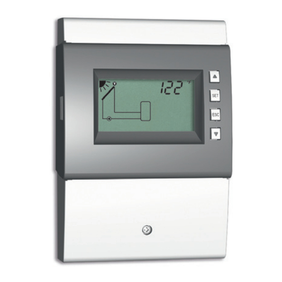
Page 15: Structure
Structure Casing No. Element section button (under Mode front panel) , SET, ESC, operating buttons Display Front panel Terminal cover 4.3.1 Terminal cover fastening – screw Section 4.3.1 describes the terminals under the terminal cover. - Page 16 6.2.2 Symbols used in the system graphics The following table describes the symbols used in the system graphics ( in Fig. 8). Symbol Description Symbol Description Pipework Pump, switched on Collector (array) Pump, switched off Maximum collector tempera- Temperature sensor ture reached Storage tank Back-up heating...
- Page 17 6.2.4 Pictograms for functions The following table describes the pictograms used for functions ( in Fig. 8). Symbol Description Symbol Description Holiday – recooling Manual operation Pump is speed controlled Freeze recirculation Interval Stagnation reduction Symbol is visible while the function/parameter is being edited in the settings menu. Symbol flashes: The function is activated and is actively intervening in the control process.
-
Page 18: Operation
Operation This section contains general information on operating the controller. Operating buttons The device is operated using the , , SET, ESC and buttons as follows: • Scrolling up through the menu/initial commissioning • Increases the setting value by 1 step • Scrolling down through the menu/initial commissioning ... -
Page 19: Off" Mode
“Off” mode Functionality • The output is switched off (output/control output without power, relays open). • Off and the software version are displayed alternately. See example in Fig. below: Software version St 1.3 • Backlighting is red. • Settings menu can be called up. • The Off mode is preset when the device is delivered. -
Page 20: Automatic" Mode
“Automatic” mode Functionality Automatic is the normal mode of operation and the system is automatically controlled. The following actions are possible: • Display status (status display): Display the status of external components (tempera- tures, switching states, run times) • Display stored min./max. values (temperature sensors) or sum/difference values (op- erating hours of the pumps and valves). - Page 21 Operation √ The controller shows the status display. You can display the status of external components as follows: X Press to display the status of other components ( , shown using system 1.1 as an example). You can display and reset the stored min./max./difference values as follows: 1.
-
Page 22: Settings Menu
Settings menu Overview The following graphic provides an overview of the structure of the settings menu. Time System Factory setting Functions Parameters SET 5 s Maximum temperature Reset to factory Set time No system – 0.1 Drainback – F01 storage tank – P01 settings 1 storage tank, Holiday –... -
Page 23: Setting The Time
Setting the time Note The time must be once more set to the correct values if power is removed for a longer period of time. After this, the same operating mode is displayed as was active previous to the removal of power. √... -
Page 24: Functions
Functions 10.1 Operation Displaying the functions The following information is visible when the functions are displayed: • Function number, e.g. F:09 (Fig. left) • Switching state: on: Function is activated off: Function is deactivated (Fig. left) Note If neither on nor off are displayed then the function cannot be used. -
Page 25: Characteristics
Setting the characteristics The functions have different numbers of characteristics. The characteristic values are always set via the same sequence of operating steps. You set the values of characteristics as follows: √ The function has been activated as described previously. 1. - Page 26 Switch-off temperature difference If a function contains a differential thermostat then the switch- of f off temperature difference can be set. The affected sensor symbols blink while settings are being performed. Switch-on temperature If a function contains a thermostat then the switch-on tempera- ture can be set.
-
Page 27: Function Descriptions
End time of a time window When setting the end time of a time window, the following is displayed to the left of the end time (see Fig. left): • • Number of time window 1 ... 3, whose end time is to be set (in this case: 1) • off Note... - Page 28 10.3.1 Drainback Notice Danger of malfunction in drainback systems • In drainback systems, the drainback function must be activated. • In drainback systems with speed-controlled solar circuit pumps note the following: – Activation of the drainback function switches off the speed control of the solar circuit pump, but this can be subsequently switched on again if desired (P:07/P:08 in Section 11).
- Page 29 Factory Display Characteristic min. max. setting Activation on, oFF Filling time 1 ... 10 minutes 3 minutes Stabilising time 1 ... 15 minutes 2 minutes Draining time: 1 ... 30 minutes 5 minutes Short startup time 0 ... 60 seconds 0 seconds 10.3.2 Holiday –...
- Page 30 10.3.3 Reduction of stagnation phases Delays the end of the storage tank's loading phase in order to reduce, or even to avoid, the system standstill (stagnation) times at high tem- peratures. To do this, the pump is stopped repeatedly, and only briefly switched on again at high collector temperatures.
- Page 31 10.3.5 Quick charge Uses a higher loading temperature to load the upper region of the stor- age tank more quickly in order to provide early prevention of back-up heating by the conventional heating system. To do this, the loading strategy of the storage tank is changed from differential loading to absolute temperature loading as soon as the temperature in the upper tank region drops below .
- Page 32 10.3.7 Upper storage tank display Shows the temperature in the upper region of the storage tank. For this, an appropriate sensor must be connected to the tank. The measured temperatures are not used for control purposes. Factory Display Characteristic min. max.
- Page 33 Type 2: Flow rate of the pulse 1.0 gal...10.0 gal, –L water meter in litres/pulse; see (no flow 1 l, 10 l, 25 l the pulse water meter data rate value sheet. selected) Glycol proportion 60 % 40 % Supply sensor input (warm) 1 ...
- Page 34 Factory Display Characteristic min. max. setting Activation on, oFF Pump type AC, HE Pump characteristics (only HE) bA, bb, C (see p. 14) – Temperature control on, oFF Sensor input for circulation 1 ... 5 – return temperature sensor Switch-on temperature T 32 °F –...
- Page 35 10.3.11 Solid fuel boiler Controls a pump in order to heat a storage tank using a solid fuel boiler. of f The pump must be connected to output R1. The pump is switched on when all of the following conditions are satis- fied at the same time: • The temperature difference between the solid fuel boiler and the storage tank exceeds T...
- Page 36 Min. solid fuel boiler temperature 85 °F 200 °F 125 °F Control target for solid fuel boiler 32 °F 200 °F 140 °F temperature (speed control = on) Notice Standard pump: Set AC! High-efficiency pump: Set HE! Notice External consumer (e.g. 115 V relay): Set AC pump type and set the speed control to oFF! 10.3.12 Heating return increase A heating return increase using a three-way valve switches on and off as follows:...
- Page 37 Factory Display Characteristic min. max. setting Activation on, oFF Pump type AC, HE Pump characteristics (only HE) bA, bb, C (see p. 14) – Sensor input 1 ... 5 – Switch-on temperature T 32 °F 350 °F 70 °F Switch-off temperature T 32 °F 350 °F 70 °F...
- Page 38 Heat source max. temperature + 4 F 350 °F 212 °F src min. src max. Heat source min. temperature 32 °F – 4 F 32 °F src max. src min. Heat sink max. temperature T 32 °F 200 °F 140 °F sink max.
-
Page 39: Parameters
Parameters Note the following when setting parameters: • Observe the operating data of the solar components used. • The individual parameters are only displayed and can be changed when this is per- mitted by the type of solar system that has been set. Special case: System 0.1 has no parameters, no P is displayed. - Page 40 Factory Display Parameters min. max. Functionality setting Storage tank loading The loading strategy depends dIFF , AbS strategy on the storage tank system used and the usage of the Control target of dif- 100 F 16 F system. ferential temperature dIFF: Highest efficiency.
-
Page 41: Dismantling And Disposal
Dismantling and disposal Danger Risk of death by electrocution! • Disconnect the device from the power supply before opening the casing. • All work on an open device must be performed by professional personnel. 1. To dismantle the controller, follow the installation instructions in the reverse order; see section 4. - Page 42 Troubleshooting Danger Risk of death by electrocution! • Immediately disconnect the device from the mains supply when it can no longer be operated safely, e.g. in the case of visible damage. • Disconnect the device from the mains power before opening the case. • All work on an open device must be performed by professional personnel.
- Page 43 Solar circuit pump not operating + switch-on condition is not fulfilled • The following functions are activated • No fault and are actively intervening in the • Deactivate the relevant func- control process: tion, if necessary. – Interval function – Holiday function –...
- Page 44 The controller has detected faulty operation Check the collector con- of the system. This is probably caused by nections. swapped collector connections. A short-circuit exists at output R1, the pump connected to output R1 flashes. Possible causes: • The pump is faulty. • Check the pump.
- Page 45 Technical data 15.1 Controller Inputs/outputs Rated voltage (system voltage) 115 ... 230 V~, 50/60 Hz Own consumption ≤ 0.8 W, two Pt1000 temperature sensors connected Output R1 Quantity Type TRIAC Switching current 1.1 (1.1) A each Voltage 115 ... 230 V~, 50/60 Hz Signal inputs/outputs Signal inputs 1 ... 5 Quantity Type of signal inputs 1 ...
- Page 46 15.2 Cable specifications Mains cable Mains cable type H05 VV-... (NYM…) External diameter of mantle 6.5 to 10 mm (0.25 to 0.4 inch) Conductor cross-section single strand (solid) ≤ 2.5 mm (#AWG 14) fine strand (with core end sleeves) ≤ 1.5 mm (#AWG 16) Diameter of the internal strain relief 6.5 to 10 mm (0.25 to 0.4 inch) Signal cable...
- Page 47 Notes ........................................................................................................................................................................................................................................................................................................................................................................................................................................................................................................................................................................................................742.110 | 14.50...
- Page 48 742110 742.110 | 14.50...
Need help?
Do you have a question about the TR-A501T-U and is the answer not in the manual?
Questions and answers