Table of Contents
Advertisement
Advertisement
Table of Contents

Summary of Contents for Pentair Pool Products IntelliComm II
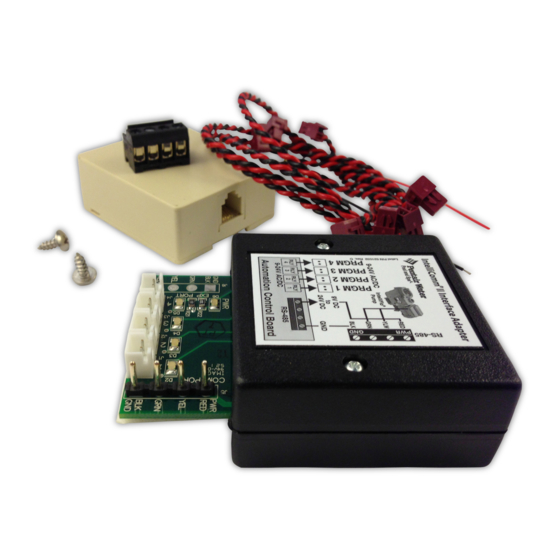
- Page 1 ® IntelliComm Interface Adapter ® ® (For use with IntelliFlo and IntelliPro pumps) Installation and User’s Guide IMPORTANT SAFETY INSTRUCTIONS READ AND FOLLOW ALL INSTRUCTIONS SAVE THESE INSTRUCTIONS IntelliComm II Interface Adapter Installation and User’s Guide...
-
Page 2: Table Of Contents
Call (800) 831-7133 for additional free copies of these instructions. Risk of electrical shock or electrocution: The IntelliComm II Interface adapter must be installed by a qualified electrician, according to the National Electrical Code (including article 680-22) or Canadian Electrical Code (including section 68) and local codes and ordinances. -
Page 3: Intellicomm Ii Interface Adapter Overview
A four screw terminal connector for connection to the RS-485 IntelliFlo communication cable and power source (9-24V DC) from the automation control system circuit board. Note: The IntelliComm II Interface adapter will always use ADDRESS 1 to communicate with the IntelliFlo pump. ®... -
Page 4: Intellicomm Ii Interface Adapter Connections
Connecting IntelliComm II to a Valve Actuator A Valve Actuator can be connected from the automation control system circuit board to any one of the IntelliComm II input terminals (1-4) by splicing into the valve actuator cable using the provided two-wire input terminal cable (see page 3). -
Page 5: Connecting Intellicomm Ii To Intelliflo
Connecting IntelliComm II to IntelliFlo TO OPERATE THE INTELLIBRITE COLOR LIGHT SHOWS Connection from IntelliComm II to an IntelliFlo VF or IntelliFlo VS pump is via a 50 ft. RS-485 communication cable (P/N 350122), which is provided with the pump. -
Page 6: Connecting To A Compool Control System
Connecting AUX cables: Choose the functions you wish to control on the Compool system. Connect the auxiliary cables (provided in kit) from the IntelliComm II input terminals (GPM/RPM 1, 2, 3, 4) to the auxiliary connector on the Compool circuit board. Typically, GPM/RPM 1 input terminal, connects to Compool FILTER PUMP output terminal. - Page 7 (for Compool CP-38xx Systems): For the Compool SOLAR system, connect the RYALX harness cable plug to the SOLAR socket, then connect the IntelliComm II pump speed plug and the VALVE cable plug to the RYALX board. The RYALX can be used for any output.
- Page 8 Connecting power to the IntelliComm II from a Compool LX100 circuit board Note: Use a RYALX Harness (P/N RYALX) If the circuit board relay output is in use and the IntelliComm II AUX cable needs to share the socket output.
-
Page 9: Ryalx Harness (P/N Ryalx) Accessory
For example, to free up an additional connection on the Compool SOLAR system, connect the RYALX harness cable plug to the SOLAR socket, then connect the IntelliComm II pump speed plug and the VALVE cable plug to the RYALX board. The RYALX can be used for any output. - Page 10 Board To power the IntelliComm II requires a two wire connection from the Compool circuit board to the IntelliComm II circuit board (as shown below). For Compool to IntelliComm II auxiliary cable connection information, see Connecting AUX cables, on page 4.
- Page 11 BLACK (GND) CP1000 RED (24 VDC) RED (24 VDC) BLACK (GND) Swim Master (LX20) CP2020 BLACK (GND) RED (24 VDC) BLACK (GND) RED (24 VDC) CP2000 and Time Master (LX10) SP100 (LX36) IntelliComm II Interface Adapter Installation and User’s Guide...
-
Page 12: Connecting To A Jandy Aqualink Rs Control System
Always disconnect AC power to the LOAD CENTER at the circuit breaker. Also, disconnect AC power to the PUMP before installing the IntelliComm II interface adapter. Failure to do so could result in death or serious injury to the service person, pool users or others due to electric shock. - Page 13 Note: The Spa output plug on the Jandy circuit board can be used for direct IntelliComm II connection, instead of splicing into the valve output cable. 230 VAC power to pump 9 - 24V DC/AC RS-485 COMMUNICATION CABLE (22 AWG)
-
Page 14: Connecting To A Hayward
Pro Logic Control System ® The following describes how to connect IntelliComm II to a Hayward Pro Logic series control system (see page 13 for connection diagram). Always disconnect AC power to the LOAD CENTER at the circuit breaker and disconnect AC power to the PUMP before installing the IntelliComm II interface adapter. - Page 15 9 - 24V DC/AC 9 - 24 VDC IntelliComm II to Hayward Pro Logic Control System Connection Diagram IntelliComm II Interface Adapter Installation and User’s Guide...
-
Page 16: Connecting To A Polaris Eos Control System
(see page 15 for connection diagram). Connecting Power to IntelliComm II from Polaris Circuit Board To power the IntelliComm II requires a two wire connection from the Polaris circuit board to the IntelliComm II circuit board (as shown on page 15). - Page 17 To IntelliFlo pump BLK (GND) From Polaris circuit board Connect to Polaris circuit board Choose the function on the Polaris circuit board (HP1-HP8, VLV1 -VLV 6) Polaris EOS Control System Load Center IntelliComm II Interface Adapter Installation and User’s Guide...
-
Page 18: Setting Up An Intelliflo Vf Pump With Intellicomm Ii
IntelliComm II will not interrupt nor take priority over Features 1 or 2. For the IntelliFlo VF to accept a command from the IntelliComm II the pump must be in the “Running” mode. To place the IntelliFlo VF in “Running” mode, press the Filter mode button, then press the Start/Stop button. - Page 19 IntelliComm II has stopped, the pump will go back to running the manually pressed speed. Note: If the IntelliComm II has switched on the IntelliFlo VS and it is running a speed and you manually adjust the pump speed using the speed buttons on the...
- Page 20 The pump will run program 3, regardless of speed, flow or order of activa- tion. When a command to run is sent from the IntelliComm II to the VS+SVRS the pump’s display will show “Running Prog. 1” and the countdown timer on the IntelliFlo VF display will show 00:01.
- Page 21 IntelliComm II Interface Adapter Installation and User’s Guide...
-
Page 22: Mounting The Intellicomm Ii Interface Adapter
Mounting the IntelliComm II Interface Adapter The IntelliComm II Interface Adapter cover (3 in. x 2 ¾ in.) can be mounted as follows: • On the inside back wall of the low voltage compartment in a load center, using the provided adhesive mounting tape. - Page 23 IntelliComm II (Back Cover) Template IntelliComm II Interface Adapter Installation and User’s Guide...
- Page 24 *521033* P/N 521033 - Rev C IntelliComm II Interface Adapter Installation and User’s Guide...
Need help?
Do you have a question about the IntelliComm II and is the answer not in the manual?
Questions and answers