Table of Contents
Advertisement
ORM0043_2
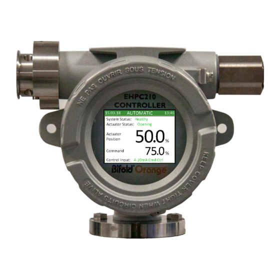
EHPC210 Universal Controller
Modulating Controller Application Manual
MC.4.24.2
Bifold FluidPower Limited – ALL RIGHTS RESERVED
The copyright in this document, which contains information of a proprietary and confidential nature, is vested in Bifold FluidPower Limited. The content
of this document may not be used for purposes other than that for which it has been supplied and may not be reproduced, either wholly or in part, nor
may it be used by, or its contents divulged to, any other person whosoever, without written permission of Bifold FluidPower Limited.
Advertisement
Table of Contents

Summary of Contents for Bifold Orange EHPC210
- Page 1 Bifold FluidPower Limited – ALL RIGHTS RESERVED The copyright in this document, which contains information of a proprietary and confidential nature, is vested in Bifold FluidPower Limited. The content of this document may not be used for purposes other than that for which it has been supplied and may not be reproduced, either wholly or in part, nor...
-
Page 2: Table Of Contents
Table of Contents 1. Introduction 1. Introduction …………………………………………………… 2 This manual provides instruction on the setup and analysis of the modulating controller application. 2. Actuator …………………………………………………………. 3 2.1 Solenoid Setup .………………………………………….. 3 Section 2 details specific actuator modules included within the application and what settings should be 2.2 Modulating Control ……………………………………. -
Page 3: Actuator
2. Actuator Feedback value should be linked to the input 2.1 Solenoid Setup providing the actuator position signal which provides a To ensure that the solenoids operate correctly based on calibrated 0-100% value. the required actuator type, the digital output contact In standard operation, 4-20mA Cmd Input should be... -
Page 4: Pulse Zones
2. Actuator Position Delay can be set to delay the actuator moving application to set the required move and pause pulse when the required movement is within two times the times depending on the location within the pulse zone. dead zone. This can be used to prevent a noisy command The standard way to set pulsing times from Limit to signal constantly trying to move the actuator when if the Balance is to decrease the Move time and increase the... -
Page 5: Digital Override
2. Actuator Close Hard Seat Fast are active then only the will be set to 0%. In both cases the controller will Command Signal needs to be below the Close Limit position the actuator based on these values. hold the Close Solenoid active. -
Page 6: Pump Setup
3. Pump Setup High Pressure SP is a high pressure alarm set point which 3.1 Pump On Demand is used to indicate that the pressure has exceeded the Pump on demand can be used on hydraulic positional maximum allowable accumulator pressure possibly systems and refers to operating a pump to open and/or caused by the pump continuously running. -
Page 7: Pump Fault
3. Pump Setup Fail On Pump Flt is active then the actuator will 3.7 High Oil Temperature position based on the fault override settings. A temperature switch can be linked to High Oil Temp 3.4 Pump Fault input to indicate that the oil temperature has reach a high temperature limit. -
Page 8: Miscellaneous
4. Miscellaneous 4.1 Supply Pressure Monitoring Supply pressure monitoring can be included on hydraulic positional systems to ensure that the hydraulic ring main pressure is above the required minimum pressure in order that the actuator can continue to be positioned. Supply Px Check is active then the hydraulic supply pressure transmitter should be linked to... -
Page 9: Display
5. Display Open Limit - Actuator is fully open 5.1 Screen 1 Close Limit - Actuator is fully closed An example of the first display screen is shown below: Pump Output - Pump is running ACTUATOR POSITION Provides the current actuator position based on the analogue signal. -
Page 10: Screen 2
5. Display Cmd Fault Stay – Faulting last due to a command signal High Temp Fault - Pump reservoir temperature is fault, but the standard fault position is either open or above temperature switch set point closed. Low Press Fault - Pressure is below minimum allowable Main Fault Open - Faulting open due to a common... -
Page 11: Appendix
6. Appendix 6.1 System Inputs Clear Fault Set active to clear a pump overrun fault Auto Mode Switch Set active to force the controller into Automatic mode Man Mode Timer Set active to force the controller into Automatic mode after a specified time 4-20mA Cmd Ctrl Set active to modulate based on the 4-20mA command signal Remote Cmd Ctrl... -
Page 12: System Outputs
6. Appendix 6.2 System Outputs Controller On Set active when the controller is powered on System Fault Set active when any fault is present in the controller Manual Mode Set active when the controller is in manual mode Opening Set active when the actuator is opening Closing Set active when the actuator is closing Open Limit... -
Page 13: System Values
6. Appendix 6.3 System Values Feedback Value indicating the actual actuator position based on an analogue signal Command Signal Value indicating the required command position based on a 4-20mA analogue signal Remote Command Value indicating a user specified required command position Open Limit Value indicating the position at which the actuator is deemed to be fully open Close Limit... -
Page 14: System Times
6. Appendix 6.4 System Times Max Manual Time Maximum time the controller can be in manual mode before being returned to automatic mode Sig Fault Delay Time an analogue signal has to be in fault before it is registered Act Limit Delay Time the actuator position has to be above the open limit or below the close limit before it is registered Position Delay...
Need help?
Do you have a question about the Orange EHPC210 and is the answer not in the manual?
Questions and answers