
Related Manuals for Spectronics Spectroline AccuMax Series


Summary of Contents for Spectronics Spectroline AccuMax Series
- Page 1 OPERATOR'S MANUAL AccuMAX Meter Series ™ XRP-3000 Radiometer/Photometer Kit AM07005-6 PRINTED IN U.S.A. September 2012...
-
Page 2: Table Of Contents
8.4 INTEGRATION (INTG) MODE......................13 9. SPECTRAL RESPONSE (THEORY OF OPERATION) …………………………..…....10. WARRANTY, MAINTENANCE AND BATTERY REPLACEMENT 10.1 WARRANTY............................15 10.2 PREVENTIVE MAINTENANCE .......................15 10.3 BATTERY REPLACEMENT ......................15 10.4 HIGH VISIBLE LIGHT READINGS ....................15 © 2012 Spectronics Corporation. All rights reserved. -
Page 3: Introduction
LCD display and is protected individuals. Ultraviolet protective eyewear and by a rugged rubber boot. Additional features of the facewear are available from Spectronics Corporation electronics include excellent temperature coefficient and for instances when UV exposure is unavoidable. -
Page 4: General Specifications
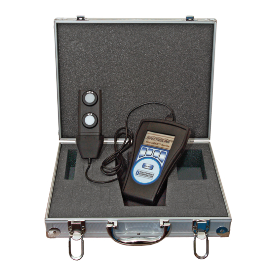
2. GENERAL SPECIFICATIONS 2.1 UNPACKING AND INSPECTION OF XRP-3000 NDT METER KIT CARRYING CASE PART NO. XCC-100 DUAL UV-A/VIS SENSOR DETECTOR PART NO. XDS-1000 PROTECTIVE RUBBER BOOT FOR READOUT UNIT PART NO. XRB-100 USB CABLE WITH WATER-RESISTANT METER READOUT UNIT SENSOR ADAPTER PART NO. -
Page 5: Technical Data
2.2 TECHNICAL DATA AccuMAX™ XRP-3000 SPECIFICATIONS Readout Unit (XR-1000) Resolution 4-digit autoranging display with backlight Screen 128 x 64-dot pixel chip on glass STN transmissive monochrome LCD 2.8 in (7.1 cm) diagonal Sampling Rate 7.5 Hz (Single Sensor) 15 Hz (Dual Sensor) Read Update 2 Hz Overall Accuracy... -
Page 6: Installation
3. INSTALLATION 3.1 CONTROLS, CONNECTORS AND INDICATORS The AccuMAX dual-sensor detector (XDS-1000) may be connected to the meter readout unit (XR-1000) by direct connection or by remote connection via USB connector (see below). Either of these options allows a complete transfer of information in digital form. -
Page 7: Controls
4. CONTROLS 4.1 BUTTONS • The sealed membrane keypad on the readout meter is equipped with five pressure- sensitive buttons that provide multiple functions and easy operation. The ON/OFF button turns the meter on and off. The four side-by-side buttons provide intuitive customer interactive functions. -
Page 8: Operation--Quick Guide
5. OPERATION––QUICK GUIDE • TO TURN ON METER, press and hold ON/OFF button for two seconds. • Displays Spectroline AccuMAX™ Series splash screen. ® • Displays Establishing Sensor Communications when sensor detector is attached. • Displays Detector Not Found/Try Cycling Power ONLY if sensor detector is NOT connected or detector was disconnected during operation. -
Page 9: Using The Accumax
6. USING THE AccuMAX 6.3 CHOOSING AN OPERATING LANGUAGE The AccuMAX is equipped to operate in four languages: English, French, German and Spanish. To access and 6.1 ON/OFF use each language, when the meter is turned on and Press and hold the ON/OFF button to turn the meter opens in the screen pictured above, press MAIN to on. -
Page 10: Customizing Settings
7. CUSTOMIZING SETTINGS Press ENTER to return to left column, DOWN to highlight EXIT and ENTER again to access UNITS. 7.2 ADJUSTING CONTRAST Press DOWN to highlight SETTINGS. Press DOWN to highlight CONTRAST. Press ENTER to access the next screen, which defaults to UNITS and LANGUAGE. -
Page 11: Adjusting Interval
7.3.1 SELECTING BACKLIGHT FOR ACTIVE AND 7.4 ADJUSTING INTERVAL BETWEEN PASSIVE OPERATIONS ACTIVE AND PASSIVE OPERATIONS Press ENTER to access the next screen where Press DOWN to highlight INTERVAL, the length of ACTIVE is highlighted. time the meter stays in ACTIVE operation before reverting to PASSIVE. -
Page 12: Accumax Operation Modes
8. AccuMAX OPERATION MODES Press PEAK to display the highest readings recorded during normal operation. The mountain peak icon will With OPERATION highlighted, press ENTER to appear. access operational screens. 8.1 ABSOLUTE DATA / NORMAL MODE When a detector is attached, AccuMAX automatically begins operating in NORMAL mode after OPERATION is selected. -
Page 13: Integration (Intg) Mode
While in ZERO mode, press HOLD to freeze the reading. The open hand icon will appear. While integrating, press FREEZE to freeze and hold the displayed data. The snowflake icon will indicate that the display is static. While in HOLD press PEAK to display the highest readings recorded during the ZERO mode. -
Page 14: Spectral Response (Theory Of Operation)
9. SPECTRAL RESPONSE (Theory of Operation) SIGNAL PROCESSING SENSOR CIRCUIT OPTICAL STAGE, A/D CONVERSION, MICROPROCESOR GRAPHICAL LIGHT PROGRAMMABLE CONTROL DISPLAY CIRCUITRY THE INPUT OPTICS photon-induced current, or photocurrent, will divide The lambertian (cosine) response of the sensor head between the diode parallel dynamic resistance and is desirable for many measurement applications, the parallel load resistance. -
Page 15: Warranty, Maintenance And Battery Replacement
Customer • Slide the battery cover back until fully in position. Service Department at Spectronics Corporation. • Return the readout unit to its rubber boot In the United States and Canada, call toll-free encasement.
Need help?
Do you have a question about the Spectroline AccuMax Series and is the answer not in the manual?
Questions and answers