
Related Manuals for AimSafety PM400

Summary of Contents for AimSafety PM400
- Page 1 AimSafety PM Multi-Gas Personal Monitor User’s Manual P/N: 34-2900-0211-2 Rev. A August 2018...
-
Page 2: Table Of Contents
Charging, Powering Up and Powering Down ............9 User Interface ....................... 11 Bump Test ......................16 Calibration ......................19 Logging ......................... 24 Cleaning and Maintenance, and Disposal ............25 Certificates ......................26 Limited Warranty ....................27 AimSafety Contact Information ................27 Page 2... - Page 3 User’s Manual WARNINGS Please ensure the device is completely free of dirt and debris before use. Regularly test the performance of the sensors past the alarm setpoints. Test the device on a regular basis to ensure that the LED, alarm and vibration function properly. Use the device under the conditions instructed, including the temperature, humidity and pressure range.
-
Page 4: General Information
User’s Manual 1. General Information The innovative new AimSafety PM 4-gas portable monitor brings enhanced convenience and flexibility to gas detection in hazardous environments. The ergonomic diffusion gas monitor simultaneously detects up to four gases, including hydrogen sulfide (H S), carbon monoxide (CO), oxygen (O ) and combustibles (LEL). -
Page 5: Different Combustible Gas Sensors
A simple press of the [Function] key acknowledges and silences the alarm. The sensor continues to stay active even though the level has exceeded 100% LEL. 2.2 Catalytic Bead technology (PM400 P) Overview 2.2.1 Advantages of Catalytic Bead technology The Catalytic sensor detects a wide range of combustible (LEL) gasses: The PM... - Page 6 User’s Manual 2.2.2 Disadvantages of Catalytic Bead technology The Catalytic sensor can be “poisoned”: Certain chemicals will damage the internal elements and cause the sensor to lose sensitivity. Common poisons are chemicals which contain silicon (found in hand lotions and industrial lubricants) and Sulfur compounds, which can be released with gases.
-
Page 7: Specifications
User’s Manual 3. Specifications 3.1. PM Specifications Gas type Detection method Diffusion Catalytic Bead Measurement type Electrochemical Electrochemical Electrochemical Infrared (PM Range 0-100 %LEL 0-30 % by Volume 0-500 ppm 0-100 ppm Sensor life > 5 years 2 years > 2 years >... -
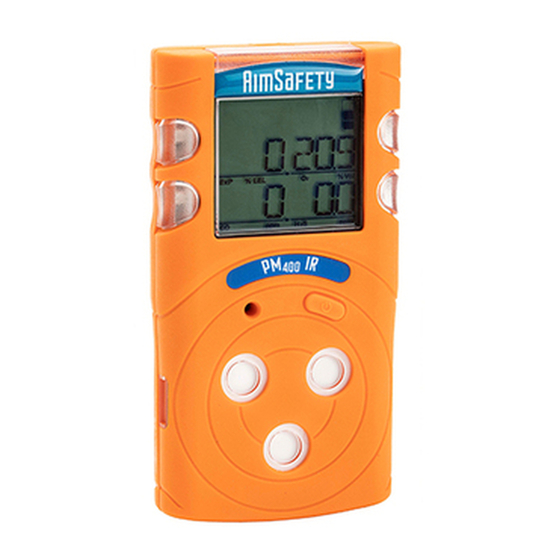
Page 8: Product Overview
User’s Manual 4. Product Overview 4.1. Monitor 3.2 Display Display symbols High Alarm Display Zero Calibration Display Device Stabilization & Low Alarm Display Calibration Succeeded Standard Gas Calibration Alarm Condition Display STEL Alarm Display Remaining Battery Display TWA Alarm Display Page 8... -
Page 9: Charging, Powering Up And Powering Down
User’s Manual 5. Charging, Powering Up and Powering Down 5.1. Charging the Device The PM ships with a power supply that plugs into a standard wall socket and with all common international interfaces. The other end connects to the device. To Charge the Device: 5.1.1 Ensure that the power supply is equipped with the interface that matches your wall’s power outlet. - Page 10 User’s Manual Note: The IR LEL sensor takes approximately an extra 90 seconds to warm up, during which time, the unit continues to display WUP in the upper-left (LEL) quadrant of the display. 5.2.3 When real-time gas readings are displayed. Note: If your device is in Safe Zone mode, the display will read SAFE ZONE when it is ready.
-
Page 11: User Interface
User’s Manual 6. User Interface The PM has two operational modes: Measuring Mode – Standard display operation with real-time gas readings always • displayed • Safe Zone Mode – Displays Safe Zone unless one or more gas concentrations exceeds an alarm set point. Gas concentrations are displayed with gas specific units of measure based on the type of gas to be detect. - Page 12 User’s Manual 6.2. Menu Screens From the Measurement screen, pressing the [Function key] will step to the next screen. Note: If you do not press the [Function key] within 10 seconds, the display reverts to the Measurement screen. Note: Pressing the [Function] key too quickly my not advance the screen. Stealth Mode: Press the [Function key] to advance to Stealth Mode (if enabled).
- Page 13 User’s Manual Alarm Values: Press the [Function key] to advance to the Setpoints screen. The Alarm Values screen displays the low alarm, high alarm, TWA, and STEL thresholds (Setpoints) for each gas. Press and hold the [Function] key for the seconds to enter the Alarm Values menu.
- Page 14 User’s Manual 6.3. Alarm and Alerts When the gas concentration exceeds an alarm set point the alarms will activate: The display will show the appropriate alarm icon(s) – High, Low, TWA, STEL, Over Range(OVL) -- and the gas level. The monitor will vibrate, the buzzer will sound, and the LEDs will flash. When an alarm activates, immediately exit the area to clean air.
- Page 15 User’s Manual Alarm Alarm Standard LCD Display Alarms and Alerts Calibration due Displays the Perform a successful Calibration specific sensor(s) calibration to clear. which require calibration. Failed calibration Displays the Calibration Perform a successful specific sensor(s) Failed calibration to clear which failed calibration.
-
Page 16: Bump Test
User’s Manual 7. Bump Test A bump test is used to test that the monitor is working properly. During a bump test, a known concentration of gas is applied to the sensors to verify that the sensors respond to the gas, and the alarms activate. This is the only way to effectively confirm that all characteristics of the monitor and the sensor are working correctly. - Page 17 User’s Manual 7.1.5 Press and hold the [Function] key for three seconds to enter the Calibration menu. CAL ZERO displays 7.1.6 Press the [Function] key twice to advance to the Bump Test screen. Bump test displays. 7.1.7 Press and hold the [Function] key for three seconds to initiate the bump test. GAS NO and a 45-second countdown timer are displayed.
- Page 18 User’s Manual 7.1.11 Clear peaks before proceeding. See Clear Peaks in the Menu Screens section for instructions. Bump Test Success Bump Test Failure If the test fails, the gas(es)/sensor(s) that failed are displayed. This failed bump test message continues to flash on the display until a successful bump test or calibration is performed.
-
Page 19: Calibration
User’s Manual 8. Calibration Calibration is the process of adjusting the sensor’s response by using a specific concentration of calibration gas. Sensors will drift for a variety of reasons, so it is important to perform a full calibration periodically to ensure that the sensors response to the target gas are accurate. - Page 20 User’s Manual 8.2. Zero Calibration (aka Fresh Air Calibration) Zero calibration adjusts the zero offset of the toxic and LEL sensors and sets the oxygen sensor to 20.9% Vol. Zero calibration must be performed in a clean environment that is free from other gases (calibration is assumed to be performed in an environment with an Oxygen concentration of 20.9% Vol.).
- Page 21 If calibration fails, the gas(es)/sensor(s) that failed are displayed. This failed calibration message continues to flash on the display until a successful calibration is performed. If calibration continues to fail, discontinue use and contact AimSafety Technical Support at support@aimsafety.com or 844-325-3050.
- Page 22 User’s Manual 8.3.3 Ensure that the regulator is firmly attached to the gas bottle and that the hose is securely attached to the regulator and to the calibration cap. 8.3.4 From the Main screen, press the [Function] key to advance to the Calibration screen.
- Page 23 8.3.9 After the calibration is complete, be sure to turn off the calibration gas. Clear the peak values, perform a Zero calibration and try again. If calibration continues to fail, please contact your sales representative or AimSafety Technical Support at support@aimsafety.com or 844-325-3050.
-
Page 24: Logging
User’s Manual 9. Logging Event logging occurs anytime that an alarm condition is met. Once an alarm condition is met the monitor will automatically save that event in the memory. The stored log events can be downloaded from your unit and exported in .XLS format using the PM Link and PC software or with the Bump Test Calibration Station. -
Page 25: Cleaning And Maintenance, And Disposal
User’s Manual 10. Cleaning and Maintenance, and Disposal 10.1 Cleaning CAUTION: Do not attempt to clean the instrument in a hazardous environment. Cleaning with a dry cloth may generate a static charge and result in an explosion. Occasionally clean the monitor with a soft cloth. Do not use detergents or chemicals. If necessary, use a damp cloth (water only). -
Page 26: Certificates
User’s Manual 11. Certificates The PM meets or exceeds the following certification standards. UL & CSA Class I, Division 1, Groups A, B, C, and/or D, T4 Ex ia IIC T4 Ga Class I, Zone 0, AEx ia IIC T4 Ga IECEx Ex ia IIC T4 Ga UL &... -
Page 27: Limited Warranty
THE IMPLIED WARRANTIES OF MERCHANTABILITY AND FITNESS FOR PARTICULAR PURPOSE ARE LIMITED TO A PERIOD OF TWO (2) YEARS FROM THE PURCHASE DATE. AimSafety shall not be liable for any incidental or consequential damages for breach of this or any other warranty, express or implied, arising out of or related to the use of said gas monitor.
Need help?
Do you have a question about the PM400 and is the answer not in the manual?
Questions and answers