
Related Manuals for Hotsy 9460


Summary of Contents for Hotsy 9460
- Page 1 9450 / 9460 Hot Water - Oil Fired Burner Modules Operator’s Manual MODELS: 9450 1.103-905.0 9460 1.103-907.0 For the Dealer nearest you, consult our web page at www.kaercher/us/.com 8.914-364.0-G 12/21/18...
-
Page 2: Machine Data Label
Machine Data Label 9450 / 9460 Operators Manual - Oil Fired 8.914-364.0 - G... -
Page 3: Table Of Contents
Control Panel ......28 9460 Left ....... . 30 9460 Right. -
Page 4: How To Use This Manual
It contains replacement parts numbers needed for ordering future parts. NOTE: The manual part number is located on the lower right corner of the front cover. 9450 / 9460 Operators Manual - Oil Fired 8.914-364.0 - G... -
Page 5: Safety
This manual should be considered a permanent part of the machine and should remain with it if machine is resold. When ordering parts, please specify model and serial number. 9450 / 9460 Operators Manual - Oil Fired 8.914-364.0 - G... -
Page 6: Important Safety Information
Failure to do this could result contenant de l'huile, de solvants ou de l'alcool. Agir in injury from a whipping wand. de la sorte risquerait de créer un incendie et/ou une explosion. 9450 / 9460 Operators Manual - Oil Fired 8.914-364.0 - G... - Page 7 Keep good footing and balance at all times. do not cover or place in a closed space where ventilation is insufficient. 19. Follow the maintenance instructions specified in the manual. 9450 / 9460 Operators Manual - Oil Fired 8.914-364.0 - G...
- Page 8 établie avec un IF CONNECTED approvisionnement en eau TO A POTABLE potable, un dispositif de WATER SUPPLY, PROTECT AGAINST protection contre le retour d'eau BACKFLOW. doit être fourni. 9450 / 9460 Operators Manual - Oil Fired 8.914-364.0 - G...
- Page 9 Notes 9450 / 9460 Operators Manual - Oil Fired 8.914-364.0 - G...
-
Page 10: Operations
Stacks Size 9450 495 Lbs 525 Lbs 10” L 32.5” X W 25” X H 50.5” 9460 865 Lbs 920 Lbs 12” L 40.5” X W 32” X H 65” 9450 / 9460 Operators Manual - Oil Fired 8.914-364.0 - G... -
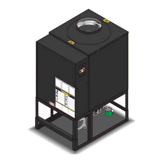
Page 11: Component Identification
Operations Component Identification Burner Exhaust Vent Detail See Control Box Illus. High Pressure Outlet Burner Switch Relief Valve Flow Switch Fuel Supply Inlet Fresh Water Inlet Power Cord 9450 / 9460 Operators Manual - Oil Fired 8.914-364.0 - G... -
Page 12: Installation
This machine, when installed, must be electrically grounded in accordance to local codes. Check for proper power supply using a volt meter. CAUTION: Use copper conductors only. ATTENTION: Utiliser des conducteurs en cuivre seulement. 9450 / 9460 Operators Manual - Oil Fired 8.914-364.0 - G... -
Page 13: Operation Instructions
(See Serial Plate). Confirm pilot light ignition, if unsuc- cessful, turn off switch and turn on again. If pilot continues to spark, but not light, consult trouble- shooting guide. 9450 / 9460 Operators Manual - Oil Fired 8.914-364.0 - G... -
Page 14: Detergents & General Cleaning Techniques
Liquids containing solvents (i.e., paint thinner, gasoline, oils, etc.) • Tri-sodium phosphate products • Ammonia or Acid-based products These chemicals will harm the machine and will damage the surface being cleaned. 9450 / 9460 Operators Manual - Oil Fired 8.914-364.0 - G... -
Page 15: Shutting Down & Clean Up
STEP 4: Open spray gun to relieve remaining pressure. 9450 / 9460 Operators Manual - Oil Fired 8.914-364.0 - G... -
Page 16: Maintenance
Solution should be allowed to circulate 2-4 hours. Step 4 After circulating solution flush entire system with fresh water. Reinstall high pressure nozzle into wand. 9450 / 9460 Operators Manual - Oil Fired 8.914-364.0 - G... -
Page 17: Relief Valve
(CAUTION 10,000 VOLTS) use defect free insulated screwdriver and keep fingers off blade! Lay blade across one contact: OK if arc will span 1/2" between end of blade and other contact. 9450 / 9460 Operators Manual - Oil Fired 8.914-364.0 - G... -
Page 18: Fuel Control System
Consider alternate nozzle configurations from the 9450 / 9460 Operators Manual - Oil Fired 8.914-364.0 - G... -
Page 19: Maintenance Schedule
If there is any sign of wear Grease Motor Every 10,000 hours Check Burner Pilot Jets Annually Pressure Relief Valve Annually Oil Change Record Date Oil Changed Estimated Operating Month/Day/Year Hours Since Last Oil Change 9450 / 9460 Operators Manual - Oil Fired 8.914-364.0 - G... -
Page 20: Troubleshooting
Check for insulation blockage or other Obstruction in smoke stack foreign objects Low engine RPM Increase RPM to correct specs. See serial plate Improper burner nozzle See exploded view parts list 9450 / 9460 Operators Manual - Oil Fired 8.914-364.0 - G... - Page 21 Defective high limit switch TEMPERATURE Replace. (thermostat) TOO HOT Incorrect fuel nozzle size See Burner Specifications. Insufficient water supplied Check GPM to machine. Restricted water flow Check nozzle for obstruction, proper size. 9450 / 9460 Operators Manual - Oil Fired 8.914-364.0 - G...
- Page 22 Notes 9450 / 9460 Operators Manual - Oil Fired 8.914-364.0 - G...
-
Page 23: Parts
Parts Parts (1.103-905.0, 1.103-907.0) 9450 / 9460 9450 / 9460 Operators Manual - Oil Fired 8.914-364.0 - G... -
Page 24: 9450 Left
9450 Left Fuel Inlet 47, 48 Fuel Return 9450 / 9460 Operators Manual - Oil Fired 8.914-364.0 - G... -
Page 25: 9450 Right
9450 Right Control Box Illus. Location Of 1st Serial For Detail Plate 18,54 Location Of 2nd Serial Plate Underside Corner Of Burner Platform Water Inlet 9450 / 9460 Operators Manual - Oil Fired 8.914-364.0 - G... -
Page 26: Parts 9450
INSULATION, RETAINER RING 8.911-630.0 BURNER MOUNT 8.900-894.0 DECAL, OPERATING INSTRUCTION 9.800-016.0 LABEL, WARNING DISCONNECT 8.901-135.0 LABEL, WINTERIZE 9.802-254.0 12" HOSE, 1/4" PUSH-ON 8.911-438.0 BRACKET, COIL 9.800-021.0 LABEL, HOT WATER OUTLET 9450 / 9460 Operators Manual - Oil Fired 8.914-364.0 - G... - Page 27 8.706-777.0 NIPPLE, 1/4" CLOSE 8.709-069.0 CLAMP, SCREW, 5/16"W, 1/4-5/8"D, SS 8.754-911.0 CHECK VALVE, 1 WAY, 1/4" BARB 8.754-893.0 FUEL NOZZLE 3.25 X 80 B W/PSI CHECK VALVE 9450 ONLY 9450 / 9460 Operators Manual - Oil Fired 8.914-364.0 - G...
-
Page 28: Control Panel
Control Panel 9450 / 9460 Operators Manual - Oil Fired 8.914-364.0 - G... - Page 29 NUT, 1/4" FLANGE, ZN 8.716-088.0 RELAY 9.802-798.0 SCREW, #10 X 1/2", PHILLIPS, ZINC 9.802-525.0 LOCKNUT, 1/2" 9.802-696.0 NUT, 10/32” 9.802-514.0 STRAIN RELIEF, STRT, LQ TITE 9.802-771.0 SCREW, 10-32 X 3/4" 9450 / 9460 Operators Manual - Oil Fired 8.914-364.0 - G...
-
Page 30: 9460 Left
9460 Left 56, 57, 58 Fuel Inlet 42, 43 Fuel Return 9450 / 9460 Operators Manual - Oil Fired 8.914-364.0 - G... -
Page 31: 9460 Right
9460 Right Location Of Control 1st Serial Box Illus. Plate For Detail Location Of 2nd Serial Plate Underside Corner Of Burner Platform 18, 54 Water Inlet 9450 / 9460 Operators Manual - Oil Fired 8.914-364.0 - G... -
Page 32: Parts 9460
CLIP, 1.25 ID ROUND 8.717-451.0 INSULATION, 24" X 24" 8.717-451.0 INSULATION, 30" X 30" 8.911-608.0 MOUNT, BURNER 8.706-236.0 TEE, 1/2" STREET 8.712-185.0 SWITCH, SNAP 8.707-286.0 WELL, THERMOSTAT 9.804-568.0 SCREW, 6/32" X 3/8" 9450 / 9460 Operators Manual - Oil Fired 8.914-364.0 - G... - Page 33 SCREW, 5/16" X 3/4" WHIZ 8.706-777.0 NIPPLE, 1/4" CLOSE 8.709-069.0 CLAMP, SCREW, 5/16"W, 1/4-5/8"D, SS 8.755-049.0 FUEL NOZZLE 4.00 X 80 B W/PSI CHECK VALVE 9460 8.754-911.0 CHECK VALVE, 1 WAY, 1/4" BARB 9450 / 9460 Operators Manual - Oil Fired 8.914-364.0 - G...
-
Page 34: Phw-Series Wayne Burner
PHW-Series Wayne Burner 9450 / 9460 Operators Manual - Oil Fired 8.914-364.0 - G... - Page 35 DESCRIPTION NOTES 12988-002 NOZZLE ADAPTER 21923-001 ELECTRODE SUPPORT KIT 13286 STEM/INSULATOR KIT 13078 CAD CELL MOUNT 13276-002 BUSS BAR SUPPORT 100850-001 CAD CELL WIRE TIE 14295 OIL PIPE FITTING 9450 / 9460 Operators Manual - Oil Fired 8.914-364.0 - G...
- Page 36 8.914-364.0 • Printed in U.S.A.
Need help?
Do you have a question about the 9460 and is the answer not in the manual?
Questions and answers