
Related Manuals for horsch Express TD


Summary of Contents for horsch Express TD
- Page 1 OPERATING INSTRUCTIONS Express TD TRANSLATION OF THE ORIGINAL OPERATING INSTRUCTIONS READ CAREFULLY PRIOR TO STARTING UP! KEEP OPERATING INSTRUCTIONS IN A SAFE PLACE! ART.: 8083 0204 ISSUE: 08/2018...
- Page 3 HORSCH: ..............Confirmation of receipt of machinery Warranty claims become only effective when the first use of the machine is reported to HORSCH Maschinen GmbH within a week. www.horsch.com under SERVICE PARTNERBEREICH an interactive PDF form is available for down- load for this purpose (not available in all languages).
- Page 4 EG-Konformitätserklärung HORSCH Maschinen GmbH Sitzenhof 1, D-92421 Schwandorf erklärt hiermit in alleiniger Verantwortung als Hersteller, dass das nachfolgend genannte Produkt: Sämaschine Express 3 TD Typ: Express 3,5 TD den einschlägigen grundlegenden Sicherheits- und Gesundheitsanforderungen der Richtlinie 2006/42/EG entspricht. Schwandorf, 24.10.2017 Klaus Winkler Dokumentationsbevollmächtigter...
-
Page 6: Table Of Contents
Table of contents Introduction ...........4 Operation .............32 Foreword ............4 Connecting/Parking ........32 Notes on representation .........4 Connecting ...........32 Service............5 Transport position .........33 Warranty claim processing ......5 Parking ............34 Consequential damage........5 Use in the field ..........35 Working speed ...........36 Safety and responsibility ......6 Headland ...........36 Intended use ...........6 Checks ............36... - Page 7 Optional equipment ........61 Bout marker ..........61 Pre-emergence markers .......62 Track loosening tines ........63 Care and Maintenance .......64 Cleaning ............64 Maintenance intervals........64 Storage ............65 Maintenance overview ........66 Waste disposal ...........69 Appendix .............70 Tightening torques ........70 Pneumatics - hose arrangement ....72 Index ............74...
-
Page 8: Introduction
DANGER to the safety notes! Highlights a danger that will lead to death or HORSCH will not assume liability for any dam- severe injury, if it is not avoided. age or malfunctions resulting from failure of complying with the operating instructions. -
Page 9: Service
Service Consequential damage The machine has been manufactured by HORSCH Company would like you to be com- HORSCH with greatest care. However, despite pletely satisfied with your machine and our the intended use deviations in placing quantity services. up to total failure may be caused by e.g.:... -
Page 10: Safety And Responsibility
Please read and comply with the following safety Horsch does not assume any liability for dam- notes, before you start using the machine! ages resulting from the unintended use of the machine. -
Page 11: Qualification Of Personnel
The person is acquainted with the function of ¾ service personnel from HORSCH. This refers to the machine within the scope of its work and the following activities: is able to assess and avoid any work related dangers. -
Page 12: Children In Danger
Children in danger Safety in traffic Children are not able to assess dangers and may DANGER behave unpredictably. Children are therefore especially endangered: No passengers are allowed to ride on the machine! Keep children away from the machine. ¾ Especially before drive off and before trigger- ¾... -
Page 13: Safety In Operation
The machine must only be put into operation ¾ qualified expert workshop. after receiving instructions by employees of the authorized dealer or a HORSCH em- ployee. The machine registration form must be com- ¾ pleted and returned to HORSCH. - Page 14 Coupling and unhitching Power sockets and connectors on the hydrau- ¾ lic connections should be marked in order to exclude operating errors. Faulty coupling of the machine to the pulling tool of the tractor causes dangers, which could result In the case of injury, contact a doctor imme- ¾...
-
Page 15: Fertiliser And Dressed Seed
HORSCH does not assume any liability for come to a standstill. damages resulting from the attachment of non-fitting pulling tools as well as incorrect Follow the operating instructions for the ¾... -
Page 16: Environmental Protection
Pick up drained operating materials with ab- ¾ HORSCH is not liable for damages to life and sorbent material or sand, fill it into a leak tight limb as well as property damages resulting from container and dispose of in accordance with unapproved retrofitting and conversions. -
Page 17: Care And Maintenance
Conform to prescribed schedules for repetitive an authorized professional workshop or ¾ by an operator who has been trained by tests or inspections. HORSCH for this purpose. Service the machine according to the ¾ maintenance plan, see chapter Care and maintenance. -
Page 18: Danger Zone
Danger zone Failing to pay attention to the danger zone can The area marked red indicates the danger zone result in severe or even fatal physical injuries. of the machine: Do not stand under lifted loads. Lower such ¾ loads to the ground first. Instruct persons to leave the danger zone ¾... -
Page 19: Safety Stickers
Safety stickers Safety stickers on the machine warn of hazards Clean soiled safety stickers. ¾ at dangerous points and are an important part Damaged or illegible safety stickers must be ¾ of the safety equipment of the machine. Miss- replaced immediately. ing safety stickers increase the risk of severe or Affix the specified safety stickers on spare ¾... - Page 20 Loading hook; hook the load suspension gear (chains, ropes etc.) into this loading hook during loading. Position of safety stickers...
-
Page 21: Technical Data
Technical data Express 3 TD 3.5 TD Working width (m) 3.00 3.50 Transport width (m) 3.00 3.50 Filling height (m) 2.21 2.21 Length without pre-emergence markers (m) 3.67 3.67 Length with pre-emergence markers (m) 4.00 4.00 Weight from (kg) 2 600 2 965 Seed hopper capacity (l) 1 500... -
Page 22: Requirements On The Tractor
Requirements on the tractor WARNING Risk of accident! Observe the permissible values of the tractor ¾ for axle loads, total weight, tyre load bearing capacity and air pressure. Verify the suitability of the tractor before com- ¾ missioning. The tractor must meet the following require- ments to be able to use the machine as intended: Implement attachment Express... - Page 23 Hydraulics Maximum system pressure 210 bar Oil grade Mineral hydraulic oil Delivery rate 20-25 l/min at 180 bar Control units, double-acting - Direct drive fan (option) - DiscSystem adjustment (auxiliary equipment) - Bout marker (auxiliary equipment) - Coulter pressure adjustment (auxiliary equipment) 1 Pressureless return flow (max.
- Page 24 Express 3 TD 2420 2630 2220 ø 540 3000 2310 3590 to 3670 (with harrow tines) 4000 Express 3.5 TD 2420 2550 2140 3500 2310 3545 to 3670 (with harrow tines) 4000...
-
Page 25: Calculating The Ballasting
Calculating the ballasting Required data: The permissible total weight, the permissible axle loads and the load bearing capacity of the tyres must not be exceeded when mounting or hitching up implements. The front axle of the tractor must always be loaded with at least 20 % of the curb weight of the tractor. - Page 26 1. Calculation of minimum front ballasting 4. Calculation of the actual total weight with rear implement: • (c + d) - T • b + 0.2 • T • b Enter the result of the calculated total weight and a + b V min the permissible total weight from the operating instructions of the tractor into the table.
-
Page 27: Design
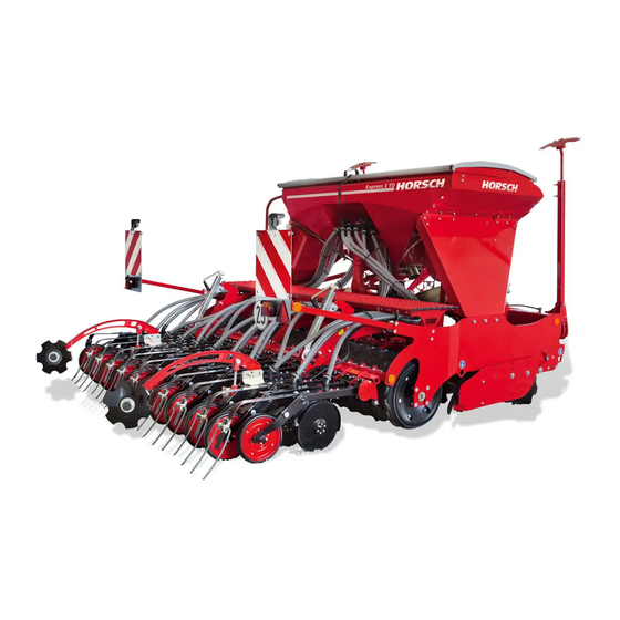
Design Overview Express TD 1 Three-point implement attachment 7 Access step and platform 2 DiscSystem, two-row 8 Distributor 3 Packer 9 Fan 4 Coulter 10 Hopper 5 Lighting 11 Bout marker 6 Coulter pressure adjustment 12 Radar sensor WARNING DANGER... -
Page 28: Hydraulics
Hydraulics Identification of hydraulic hoses The symbol is always located above the hose WARNING that requires pressure to bring the machine in Accidental hydraulic movements (e.g. caused transport position (lift out, folding, etc.). by passengers or children) can lead to severe accidents and injuries! Secure or lock the control units on the tractor. - Page 29 Fan - direct drive 1 Tractor control unit 2 Hydraulic coupling, flow 3 Hydraulic coupling, return 4 Pressure gauge 5 Geared motor 6 cm³ 6 Pressure limiting valve (in the engine) Fan - PTO-shaft drive 1 Gear pump 61 cm³ 5 Pressure limiting valve (in the engine) 2 Flow control valve 6 Oil cooler...
- Page 30 Direct drive fan with pre-emergence markers (without bout marker) 1 Tractor control unit 2 Hydraulic coupling, flow 3 Hydraulic coupling, return 4 Pressure gauge 5 Geared motor 6 cm³ 6 Pressure relief valve 7 Restrictor ø 1 mm 8 3/2-way valve 9 Hydraulic cylinder pre-emergence marker Pre-emergence markers and bout marker 1 Tractor control unit...
- Page 31 Hydraulic depth settingDiscSystem 1 Tractor control unit 4 Double acting lock valve 2 Hydraulic coupling - lower 5 Hydraulic cylinders 3 Hydraulic coupling - lift Hydraulic coulter pressure adjustment 1 Tractor control unit 4 Switch for work signal 2 Hydraulic coupling 5 Hydraulic cylinders 3 Pressure gauge...
-
Page 32: Lighting
Lighting WARNING Traffic accidents caused by defective lighting. Ensure cleanliness and tight fit of the plug- ¾ and-socket connections. Check the lighting before setting off. ¾ Check warning boards and lighting equipment ¾ for cleanliness. 7-pin plug Rear light, right Lamp, direction indicator Lamp, tail light Lamp, brake light... -
Page 33: Instruction Stickers
Instruction stickers Clean soiled stickers. ¾ Damaged or illegible stickers must be re- ¾ placed immediately. Apply the specified stickers to spare parts. ¾ If the return flow pressure exceeds 2 bar Hydraulic coulter pressure adjustment The increase of the coulter pressure is replace the filter and change the oil. - Page 34 Hitching / uncoupling (only for France) „ Atteler à un tracteur dont le relevage est équipé de dispositifs de blocage latéraux et verticaux“. „Pour circuler sur la route, respecter la hauteur d’attelage spécifiée dans la notice d’utilisation et bloquer le relevage“. 00380900 Driving with empty seed hopper (Only for France)
-
Page 35: Commissioning
These work activities may be carried out only by Attach lifting tackle only at the marked points. ¾ persons trained by HORSCH for this purpose. Ballasting Pay attention to the notes in the ¾ chapter. -
Page 36: Operation
Operation WARNING Leaking hydraulic fluid can cause serious in- Whenever working on the machine juries! Danger of injury by unwanted machine pay attention to the associated safety movements. notes in the chapter "Safety and Connect and disconnect the hydraulic lines prevention of accidents"... -
Page 37: Transport Position
5. For fan with PTO-shaft drive: NOTE - Plug the PTO-shaft pump on the PTO- shaft journal of the tractor. Make sure before driving on public roads that ¾ - Secure the PTO-shaft pump with the the machine meets all respective applicable bracket against twisting, see chapter road traffic regulations. -
Page 38: Parking
Parking DANGER Risk of accident due to insufficient stability Park the machine on a flat and paved surface. ¾ NOTE Before parking for an extended period: Park the machine in a hall or under a roof. ¾ Clean the machine and prepare it accordingly, ¾... -
Page 39: Use In The Field
Use in the field NOTE 1. Connecting the machine, see Connecting. Ad- Please note: just the lifting point of the upper link according To control the seed refer to the operating to the field conditions. • instructions for the E-Manager 2. -
Page 40: Working Speed
Working speed Checks The working speed depends on the field condi- NOTE tions (soil type, crop residues etc.), seed, seed quantity, coulters and other factors. Check the placement quality when beginning ¾ to work (after a few metres of drilling) and with larger fields also in between on all coulters: NOTE Drilling depth... -
Page 41: After Sowing
After sowing Is the hydraulic fan connected to a pressure- ¾ Empty and clean the hopper and metering unit free return flow? after sowing. Are fan wheel and intake grille clean? ¾ Seed and dressing may otherwise become Is the fan wheel tightly mounted on the shaft? moist, sticky and cause seed bridging in the ¾... -
Page 42: Settings
Settings Hydraulic adjustment (option) The hydraulic adjustment allows adjusting the working depth of the DiscSystem infinitely vari- WARNING able during field work. Risk of accident from unauthorised starting of The setting of the DiscSystem is shown on the the tractor and triggering of machine move- scale: ments. -
Page 43: Track Loosening Discs
Track loosening discs Adjust the working depth of the track loosen- ¾ ing discs through the hole pattern. To be able to loosen and level the tractor tracks, Tighten screw and nut (3). ¾ certain disc pairs of the DiscSystem can be set Check the working results of the track loosen- deeper. -
Page 44: Farmflex Packer
FarmFlex Packer FarmFlex Packer Rubber roller with excellent consolidation on medium soils. Leaves a wavy profile. As DoubleDisc packer insensitive to wetness. Particularly suitable for stony soils. Scraper Readjust the scraper via the slotted hole if ¾ worn (approx. 5-7 mm distance to the packer). ¾... -
Page 45: Pneumatic System
Pneumatic system The generated air flow conveys the seed from the fall sluices to the coulters. The required air quantity depends on seed (type and weight), The pneumatic system consists of seed quantity, working width and sowing speed. A correct fan speed cannot be specified and •... -
Page 46: Direct Drive
Connecting the hydraulics NOTE CAUTION Fan wing and protective grid must be regularly ¾ checked for dirt deposits and cleaned. Damage on the fan motor - gear motor Deposits on the protective grid restrict the air Connect the return line to the pressureless flow and thus lead to blockage in the seed ¾... -
Page 47: Pto-Shaft Drive (Option)
PTO-shaft drive (option) Adjusting the fan speed The fan can alternatively also be driven by a PTO-shaft pump. Mounting the PTO-shaft pump DANGER Danger of injuring during assembly Before performing assembly work shut down ¾ the tractor and pull off the ignition key! Never switch on the PTO-shaft with the en- ¾... -
Page 48: Checks And Maintenance
Checks and maintenance Retightening the fan flange The clamping taper fixates the fan wheel and additionally clamps on the drive shaft. WARNING The clamping taper on the fan drive may come loose. The impeller can thus move along the Risk of injury from running fan drive shaft and damage the fan. -
Page 49: Hopper
Hopper Discharge gate A discharge gate is mounted on the side of the hopper: Hopper Access steps Platform Covering Loosen the interlocking (5). ¾ Pull up the discharge gate (6) to empty the Covering ¾ hopper. The hopper is closed with a covering. Platform WARNING Risk of injury when opening and closing the... - Page 50 Loosen the interlocking (4) to enter the plat- ¾ form and fold down the access steps. Fold up the access steps and let it engage ¾ after leaving the platform.
-
Page 51: Metering Unit
Metering unit Rotors The HORSCH metering unit consists of only A large number of rollers is available for the a few individual parts and can be dismantled different seed types with numerous geometrical without tools. shapes and grain sizes, as well as fertilisers in form of powders or granulates. -
Page 52: Roller Change
Roller change Roller change with gate valve After choosing a rotor from the table it must be installed in the metering unit. Changing the roller while the hopper is full is easier if a gate valve is provided above the Empty the seed hopper, if possible, before ¾... -
Page 53: Roller Change At Full Hopper Without Gate Valve
Roller change at full hopper Adjusting the sealing lip without gate valve NOTE A defective sealing lip or incorrectly assembled supporting plate cause metering errors during sowing. The sealing lip must not be torn or damaged. ¾ Replace the sealing lip at least 1 x per year. Insert the side cover with the sealing lip into ¾... -
Page 54: Rotors For Fine Seeds
Rotors for fine seeds Removing or installing a fine seed roller The anti-rotation locks must be turned towards The rollers for fine seeds consist of cell discs, the recess in the housing in order to install and spacers and drive shaft. remove the rollers. -
Page 55: Rape Brushes
Rape brushes The spacers are equipped with bearings. Depending on the manufacturing tolerance shims are added to avoid any friction between cell discs and spacers. The rape brushes clean the cell discs in the rollers for fine seeds. After the assembly of all parts the remaining gap to the lock washer is filled up with shims. -
Page 56: Coarse Seeds
Urheberschutz: Für diese technische Unterlage DIN 6784 behalten wir uns alle Rechte vor. 17.04.2012 Haselhoff Adapter Bohnen für Dosiergerät PP © Horsch Maschinen GmbH © Horsch Maschinen GmbH Änderungen sind untersagt Änderungen sind untersagt 01508300 6,115 kg Bemaßungen in mm... -
Page 57: Maintenance Of The Metering Unit
Maintenance of the Metering unit with injector fall sluice metering unit The metering units in machines with normal hopper and injector fall sluice are equipped with The metering unit does not require any special a lid (V2A) with machined recesses. maintenance. -
Page 58: Calibration
Calibration Distributor A distributor tower is attached to the seed hopper for seed distribution. CAUTION Risk of crushing on the metering unit NOTE Do not reach into the rotating metering unit. ¾ All distributor components must be leak tight. Even slightest leaks and air losses will cause uneven distribution. - Page 59 Marking tram line valves (position open) If the tram line distribution box is equipped with a track width change-over, the track width must only be changed when the valves are open. This can be checked on the terminal (no tram line must be switched) or by checking the marks on the valves.
-
Page 60: Coulter
Coulter NOTE Overview With wet or loose soils the pre-tension of the • coulter discs must not be too high to make sure that the discs will not block up and wear unevenly. The coulter discs must be slightly preloaded at •... - Page 61 Coulter disc scraper Uniformer The scraper features self-adjusting carbide tips The uniformer firms the seed in the seedbed and glued to the edges. presses it gently down. Under moist conditions and sticky soils the Ensure even, slightly angular contact across ¾...
- Page 62 Increase the angle of attack (aggressiveness): ¾ NOTE Slightly lift the seed bar and screw down the screw (2) in the upper position behind the Set the press roller to the upper position for harrow. ¾ deep seed placement. Adjust all harrows equally. ¾...
-
Page 63: Depth Setting
Depth setting NOTE The drilling depth is determined by the depth The settings of drilling depth and coulter ¾ setting and the coulter pressure on the coulters. pressure affect each other. Check the coulter The drilling depth is adjusted mechanically via pressure in the field after each change of the two racks. - Page 64 Manual coulter pressure adjustment NOTE The coulter pressure can be increased by back- The placing quantity of the seed is increased ing out the screw adjustment. automatically with the hydraulic increase of the Pay attention to the engraved adjusting scale. ¾...
-
Page 65: Optional Equipment
Optional equipment Adjusting the aggressiveness Bout marker WARNING Risk of injury from the bout marker. Order persons to leave the slewing range of ¾ the bout markers. Bout marker disc adjustment When installing for the first time, the bout mark- ers must be set to working width. -
Page 66: Pre-Emergence Markers
Pre-emergence markers Depth setting The pre-emergence markers can be adjusted WARNING in 4 stages: Danger of injury Stage 1 - flattest position • Stage 4 - deepest position Make sure before operating the pre-emer- • ¾ gence marker that no persons are present in the danger zone. -
Page 67: Track Loosening Tines
Adjusting the working depth Track loosening tines The working depth must be adjusted to the By loosening deep tractor tracks the disc system respective soil conditions and the tractor used. is able to work in shallower working depths. The track loosening tines are secured against Loosen the cotter pin and pull out the bolt (2). -
Page 68: Care And Maintenance
Care and Clean the outside of the machine with water. ¾ Open the fall sluice under the metering unit Maintenance so that entered water can flow off. Clean the cell wheel inside the metering unit ¾ with a brush and compressed air. Blow out coulters, seed lines, seed hopper, WARNING ¾... -
Page 69: Storage
Storage If the machine is to be shut down for a longer period of time: If possible, park the machine under a roof. ¾ Completely empty and clean the seed and ¾ fertiliser hopper. Reduce the coulter pressure adjustment to ¾... -
Page 70: Maintenance Overview
Maintenance overview Express TD Maintenance location Work instructions Interval After 10 operating hours Retighten all screw and plug-in Even firmly tightened screw connections can come loose (e.g. once connections as well as the hydraulic because of material settlement or paint residues between the connections. - Page 71 Maintenance location Work instructions Interval Check for leaks, function, speed setting daily Protective fan grid Clean from contamination as required Impeller wheel Check condition and fastening, clean of dirt deposits daily Tighten the drive flange (first time 50 hrs) yearly Leak oil return flow Return flow pressure max.
- Page 72 Lubrication points (lubrication grease: DIN 51825 KP/2K-40) - Lubricate the following, number of lubrication points in brackets Lubricate bout marker bearings (2x) 40 h Lubricate hydraulic cylinders bout marker (2x) (2 each) 40 h Lubricate coulter pressure adjustment crank (1 each) yearly and DiscSystem (2x each)
-
Page 73: Waste Disposal
Attention must be paid to all valid regulations. Decommissioning and waste disposal must only be carried out by operators who have been trained by HORSCH. Contact a waste disposal company, if this should be necessary. -
Page 74: Appendix
Appendix Tightening torques NOTE The tightening torques only serve as guidelines and are generally valid. Actual data given at the • corresponding points in the operating instructions have priority. Screws and nuts must thereby not be treated with lubricant, since this would change the friction value. •... - Page 75 Inch screws Tightening torques - inch screws in Nm Screw Strength 2 Strength 5 Strength 8 diameter No marks on head 3 marks on head 6 marks on head Inch Coarse Fine thread Coarse Fine thread Coarse Fine thread thread thread thread 12.2...
-
Page 76: Pneumatics - Hose Arrangement
Pneumatics - hose arrangement The outflows on the distributors are allocated to the individual outlets on the seed bar through numbering. NOTE Uniform seed placement can only be ensured when the seed transport to the coulters is working. Observe correct hose installation. ¾... - Page 77 Express 3.5 TD Distributor Direction of travel Output Distributor 13 22 14 19 20 18 17 16 24 23 15 Coulter No. 10 11 12 13 14 15 16 17 18 19 20 21 22 23 24 15 16 17 18 19 Tram line valves Track width Tram line valves...
-
Page 78: Index
Index Accessories 6 Fall sluice 47 Adapter frame 52 Fan 25,37,41 Assembly 50 Fan blades 42,44 Fan - fertiliser 67 Fan flange 44 Bout marker 26,61,67 FarmFlex Packer 17,40 Fertiliser metering unit 67 Filling height 17 Cable 28 Flange 44 Calibration 54 Foreign objects 51 Care 13... - Page 79 Packer 11,40,67 Technical data 17 Parking 34 Top speed 9 Pin assignment 53 Track loosening discs 39 Platform 45 Track loosening tines 63 Plug 28 Tractor 18 Pneumatic system 37,41,66,72 Tractor link arm shaft 67 Pre-emergence markers 26,62,67 Traffic 8 Press rollers 17,57,67 Tram line control 54 Pressure accumulator 10...
- Page 81 All details on technical specifications and pictograms are approximate and for information only. Subject to technical product revisions. HORSCH Maschinen GmbH Tel.: +49 94 31 7143-0 Sitzenhof 1 Fax: +49 94 31 7143-9200 92421 Schwandorf E-Mail: info@horsch.com www.horsch.com...
Need help?
Do you have a question about the Express TD and is the answer not in the manual?
Questions and answers