Table of Contents

Summary of Contents for DeltaPoint Manifold DPM-12GM-6-P1A-FP10-F-V1
- Page 1 DeltaPoint Manifold ™ Installation and Operation Manual 12 GPM PROFINET Unit Model DPM-12GM-6-P1A-FP10-F-V1 ROCON LLC 1755 East Nine Mile Road PO Box 249 Hazel Park, MI 48030-0249 TEL (248) 542-9635 FAX (248) 398-4274 Website: www.flowmeters.com...
-
Page 2: Table Of Contents
FRONT VIEW, ELECTRICAL ENCLOSURE, COVER REMOVED............8 UNIT REAR VIEW ............................. 9 UNIT SIDE VIEW ............................ 10 HOW THE DELTAPOINT MONITORS COOLING WATER IN THE ROBOTICS CELL ......11 INSTALLATION ............................12 START-UP TEST CYCLE ........................13 ELECTRICAL CONNECTORS ....................... 14 INDICATOR LIGHTS, PROGRAMMING KEYPAD, AND LCD MESSAGES EXPLAINED .... -
Page 3: Proprietary Notice
ROCON LLC PROPRIETARY NOTICE The information contained in this publication is derived in part from proprietary and patented data. This information has been prepared for the express purpose of assisting in installation, operation, and maintenance of the instruments described herein. Publication of this information does not convey any rights of use or reproduction other than in connection with the installation, operation and maintenance of the equipment described herein. - Page 4 ROCON LLC USING THIS MANUAL In order to use this manual, you will need the model code that can be found on the nameplate of the flowmeter, as shown on the example below (see MODEL CODES). The Model Code allows you to determine minimum and maximum flow capabilities for the Delta Point water saver.
-
Page 5: Specifications - 12 Gpm (45 Lpm) Unit
ROCON LLC SPECIFICATIONS – 12 GPM (45 LPM) UNIT Supply Voltage 24 VDC @ 750 mA (valve on) Minimum Water Flow: 0.8 GPM (3 LPM) Maximum Water Flow: 12.0 GPM (45 LPM) Flow Measurement Accuracy: ±0.24 GPM (±0.9 LPM) Flow Measurement Repeatability: 0.25% of actual flow Minimum Detectable Leak: 0.5 GPM (1.9 LPM) -
Page 6: How Vortex Shedding Flow Meter Works
(flow). The pulses are then measured by the microprocessor. Each DeltaPoint Unit has two vortex shedding flow meters. One flow meter monitors the supply path, and the other flow meter monitors the return path along with the temperature probe. -
Page 7: Unit Front View
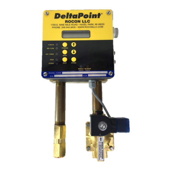
ROCON LLC UNIT FRONT VIEW A = Solenoid NC 2way Shutoff Valve 1 = Supply B = Manual Bypass Knob 2 = To Cell C = Check Valve 3 = From Cell D = Cover - LCD Screen 4 = Return E = Cover - LED / Program Buttons F = ID Tag G = PROFINET Connector... -
Page 8: Front View, Electrical Enclosure, Cover Removed
ROCON LLC FRONT VIEW, ELECTRICAL ENCLOSURE, COVER REMOVED A = Motherboard (CPU and Keypad) B = LCD Screen C = Analog Board (power supply and sensor amplifiers) D = Supply Flow Sensor E = Return Flow Sensor F = Return Temperature Sensor G = Solid State Relay (supply water control) H = Optional Drawback / Venturi Solid State Relay I = USB Port (Firmware Updates / Data Logging) -
Page 9: Unit Rear View
ROCON LLC UNIT REAR VIEW Supply flowmeter bluff USB Port for firmware updates Return flowmeter bluff DPM-12GM-6-P1A-FP10-F-V1 10/31/2018... -
Page 10: Unit Side View
ROCON LLC UNIT SIDE VIEW A = Power connector B = PROFINET connectors C = Shutoff valve DIN connector with LED D = Supply valve E = Valve manual override knob E = Valve manual override knob F = Stamped “C” DPM-12GM-6-P1A-FP10-F-V1 10/31/2018... -
Page 11: How The Deltapoint Monitors Cooling Water In The Robotics Cell
HOW THE DELTAPOINT MONITORS COOLING WATER IN THE ROBOTICS CELL Each DeltaPoint unit has two vortex shedding flow meters. One flow meter monitors the supply path, and the other flow meter monitors the return leg. The fluid strikes a bluff body, generating vortices (eddies) that move downstream. -
Page 12: Installation
ROCON LLC INSTALLATION 1. DeltaPoint unit is preferred to be mounted on the outside of the fence line, for ease of service. 2. DeltaPoint can be mounted in any orientation: horizontally, vertically or at any other angle. The orientation has no effect on performance. It is suggested that unions or hosing be used when connecting to the main supply and return piping, this will facilitate ease of maintenance or removal of unit if needed. -
Page 13: Start-Up Test Cycle
ROCON LLC START-UP TEST CYCLE Shut-Off Fault Alarm and PROFINET Master Fault Alarm Test If unit is operational with water flow present: 1. Turn one of the cooling water shutoff valves OFF. 2. The LCD screen indicates “Water Flow Fault.” 3. -
Page 14: Electrical Connectors
ROCON LLC ELECTRICAL CONNECTORS Supply Power Connector 1 = 0V Out 2 = 0V Sensor 3 = Chassis GND 4 = 24V Sensor 5 = 24V Out Dual PROFINET Supply Ports Power DPM-12GM-6-P1A-FP10-F-V1 10/31/2018... -
Page 15: Indicator Lights, Programming Keypad, And Lcd Messages Explained
ROCON LLC INDICATOR LIGHTS, PROGRAMMING KEYPAD, AND LCD MESSAGES EXPLAINED Color Status Function Comments Programmable. Flow => Flow OK setpoint. LCD shows “Flow Green Solid OK” Programmable. Temperature exceeds Temp. Fault setpoints Green Solid Temperature Fault High or Low. LCD shows “Fault” on the second line. Solid Low Flow, Minimal See below. -
Page 16: User Menu Features
ROCON LLC User Menu Features 1. Pressing the PROGRAM button takes user into the “Options Menu” 2. Successive Presses of PROGRAM button displays the following menu options. Use UP or DOWN button to increase or decrease the setpoints and press ENTER to save it. a. - Page 17 ROCON LLC Important Note Priority will always be given to the settings sent from the PROFINET Master. The change of setpoints from the user button requires: 1. PROFINET Master is not connected or, 2. PROFINET Master sends 0 to the corresponding setpoints 3.
- Page 18 ROCON LLC Fault notification Fault messages Display: Fault messages for caploss or over or under temperature will be displayed next to the reading that relates to the fault Fault messages such as Return > Supply, Fault will be displayed in the lower row of the LCD display.
-
Page 19: Profinet Led Lights
ROCON LLC PROFINET LED LIGHTS The Module Status LED has the follow states: MS LED State Description The PROFINET Module is not active/not powered. Flashing Green The PROFINET Module is in standby. Solid Green The PROFINET Module is ready Flashing Red The PROFINET Module has a recoverable fault. -
Page 20: Profinet Setup
ROCON LLC PROFINET SETUP Software Used 1. PROFINET Commander v3.1 2. Siemens “SIMATIC NET, PC Software, Edition 2008+SP2” Setting up SIMATIC NCM Manager 1. Open the SIMANTIC NCM Manager software and double click on Configuration. Then go to Options-> Install GSD file. DPM-12GM-6-P1A-FP10-F-V1 10/31/2018... - Page 21 ROCON LLC 2. Locate the GSDML file provided with the device and install it. Once installed, it should be visible under PROFINET IO -> Additional Field Devices -> General -> Anybus CompactCom PRT 2-Port. DPM-12GM-6-P1A-FP10-F-V1 10/31/2018...
- Page 22 ROCON LLC 3. Click on the “Ethernet: MainPC” Line and go to Insert-> Insert object. Click on Additional Field Devices -> General -> Anybus CompactCom PRT 2-Port -> RT (FW >= 1.13) DPM-12GM-6-P1A-FP10-F-V1 10/31/2018...
- Page 23 ROCON LLC 4. Right click on the Object slot as shown below and click on “Insert Object”. 5. Insert the inputs and outputs in accordance with the following bitmap: Name Size Remarks Status Input 1 Byte Supply Flow Input 1 Byte Transmitted as 10 x Flow Return Flow Input...
- Page 24 ROCON LLC The inputs and outputs are inserted accordingly as shown below. Name Size Remarks Status Input 1 Byte Supply Flow Input 1 Byte Transmitted as 10 x Flow Return Flow Input 1 Byte Transmitted as 10 x Flow Water Temperature Input 1 Bye Transmitted as 1 x Temperature...
- Page 25 ROCON LLC 6. Click on “Save and Compile” to look for errors if any. 7. Export the configuration file by clicking on “Export”. This file will be used with the PROFINET Commander Software to look up the data from the device. File will be saved in .cfg format. Assume “PCStation.cfg”...
- Page 26 ROCON LLC Click on the device block as shown in the figure. Then Click on PLC- Ethernet - Assign Device name 9. Click on Assign name and you should be able to see the name you assigned to the device block under the Device name column.
- Page 27 ROCON LLC 10. To see if everything went correctly, go to PLC-> Ethernet-> Verify Device Name 11. You should see the Device name and IP address Assigned to the device. There should be a green checkmark under the status. DPM-12GM-6-P1A-FP10-F-V1 10/31/2018...
- Page 28 13. The settings will get downloaded into the software PLC. You are all set to test the device with PROFINET Commander now. Steps for using PROFINET Commander for DeltaPoint 1. Open PROFINET Commander 2. Click on Open Config File Button and select the configuration file saved earlier.
- Page 29 ROCON LLC each input and output can be seen as “GOOD” or “BAD”. “BAD” means the configuration is not correct. DPM-12GM-6-P1A-FP10-F-V1 10/31/2018...
- Page 30 ROCON LLC 4. To see the individual status bit, change the I/O Display Format in the PROFINET Commander to Binary. The Status Bits are as follows: (counted from right to left, see the figure above ) Bit 0: Flow Okay To Weld (1: Okay to weld) Bit 1: Valve Closed (1: Valve is closed) Bit 2: Bypass On (1: Bypassed) Bit 3: Minimal Flow (1: Flow is sufficient)
- Page 31 ROCON LLC 5. To send 1 or 0 to the individual output bits, double click the corresponding output under the Output column Change the bit that you want to change and press OK. Command Bits: (From right to left in the above software window) Bit 0: Reset Signal (1 = puts the device into reset until set to 0) Bit 1: Shutoff Signal (1 = Shuts off the valve until set to 0) Bit 2: Bypass Signal (1 = Sets the device into bypass mode)
-
Page 32: Profinet I/O Map Summary
ROCON LLC PROFINET I/O MAP SUMMARY Input Means from the Water Saver to the PROFINET Master Output Means from PROFINET Master to the Water Saver Name Size Remarks Input Status 1 Byte Input Supply Flow 1 Byte Transmitted as 10 x Flow Input Return Flow 1 Byte... -
Page 33: Status Byte Bit Summary
ROCON LLC STATUS Byte Bit Summary 1=flow 1= Temp above 1=Bypass Temp 1=Cap Bit Status Table exceeds 1=bypassed 1=closed 1=OK Requested below Loss DP PROFINET setpoint flow setpoint Rev. 1.00 setpoint Released: Under Flow Bypass HighTemp Leak Bypass Valve 12/5/2014 Temp Flow Request... -
Page 34: Outputs
ROCON LLC OUTPUTS From PROFINET Master to the Water Saver DESCRIPTION Tag Name Command bit1: Reset watersaver (1 = Reset) Reset Command bit2: Shutoff water (1 = shut off) Shutoff Command bit4: Bypass (1=bypass on) Bypass Command bit8: reserved Command bit16: reserved Command bit32: reserved Command bit64: reserved Command bit128: reserved... -
Page 35: Front Panel Controls And Corresponding Bits
ROCON LLC Front Panel Controls and Corresponding Bits Flow Ok LED Min Flow LED Flow Ok LED Flashing Min Flow LED Flashing Min Flow YELLOW Low Flow YELLOW Flow OK GREEN Selectable Does Valve Shut Signal Output? Output LED Indicator in Alarm? Cap Loss Fault Flow OK red/Min Flow... -
Page 36: Maintenance
ROCON LLC MAINTENANCE DeltaPoint water savers require no maintenance. If the flow tubes become clogged with debris, the unit should be removed for service and cleaning. Significant clogging may result in erratic operation, errors or faults. Do not place tools into the tubes, as this may permanently damage the vortex sensor. The vortex sensor cannot be repaired. -
Page 37: Troubleshooting
Page 19 PROFINET “Module Status” PROFINET LED LIGHTS on Page 19 DeltaPoint does not respond to Check the PROFINET Master program to make sure these remote shut-off and/or restart bits are correctly transmitted to the water saver (see commands from PROFINET PROFINET I/O MAP). - Page 38 ROCON LLC Step 2 – Using a 3/32 Allen Head Wrench remove both Bluffs’ hold down screws. Remove bluffs, is there debris on ether bluff – remove. Step 3 – Solenoid Valve – switch to BYPASS position. Step 4 – Tighten the bleed off hose fitting or replace cap. Step 5 –...
-
Page 39: Replacing The Flow Sensor
ROCON LLC This usually is a “return sensor” problem. SUPPLY FLOW is greater than Refer to “COMPARISON TESTING” and “FLUSHING THE RETURN FLOW (Unit continuously faults out) BLUFF”. This usually is a “supply sensor” problem. RETURN FLOW is greater than Refer “COMPARISON TESTING”... - Page 40 ROCON LLC Step 1: Remove the 4 corner screws. Step 2: Lift the left side of the cover plate Slide to left Step 4: Take out the M12 external O-rings and save them. Step 3: Slide the cover plate to the left until the M12 data connectors slide out of the metal shells.
- Page 41 ROCON LLC Step 6: Remove the flexible cable between the two boards. Note the orientation and the bare contact side of the wires. Then remove the USB connector Step 7: Remove the screws from hold-down bracket of the sensor to be swapped. Note the headers where the sensor wires are plugged in.
- Page 42 ROCON LLC Remember to install the external O-rings in the metal shells after the installation is completed. DPM-12GM-6-P1A-FP10-F-V1 10/31/2018...
-
Page 43: Dimensions
ROCON LLC DIMENSIONS DPM-12GM-6-P1A-FP10-F-V1 10/31/2018... -
Page 44: Appendix
ROCON LLC APPENDIX Check Valve Specifications Style: Piston Check Valve with embedded O-ring that seals on seat Maximum operating pressure: 500 PSI (34.5 bar) Maximum operating temperature: 180 °F (82 °C) Cracking Pressure: 1 PSI Material: Brass Body and Piston, Beryllium Copper Ring Shut-Off Valve Specifications Function: 2-Way Normally Closed... -
Page 45: Rma Notice Return Material Authorization
ROCON LLC RMA NOTICE RETURN MATERIAL AUTHORIZATION Please read the following UFM policy information carefully. By following the guidelines outlined below you will assist in providing a timely evaluation and response regarding the status of your flow meter. UFM evaluates all AUTHORIZED RETURNED MATERIALS in a timely manner and will promptly provide notification regarding the status of the related materials and/or a written quotation indicating the total charges and description of the necessary repairs. -
Page 46: Rma Form
ROCON LLC RMA FORM DPM-12GM-6-P1A-FP10-F-V1 10/31/2018... -
Page 47: Rocon / Deltapoint Warranty
ROCON LLC ROCON / DELTAPOINT WARRANTY 1) ACCEPTANCE AND INTEGRATION CLAUSE: This Sales Order Acknowledgment and the sales order information that Rocon LLC attaches to or associates with it (this “Acknowledgement”), constitutes an acceptance by Rocon of an offer by the buyer upon the conditions and terms and at the prices stated in this Acknowledgement.
Need help?
Do you have a question about the Manifold DPM-12GM-6-P1A-FP10-F-V1 and is the answer not in the manual?
Questions and answers